

Don’t let the name fool you; the Deck-Drive™ DSV Wood screw is more than just a deck screw. It’s not only great for preservative-treated decking, but can also be used for general framing and construction as well. The variety of sizes makes this a multipurpose screw that can accomplish many of your wood-to-wood fastening needs.
Tag: loads
Second Day of Trivia – Hurricane Ties
I recently wrote about the H1A hurricane tie in this post, which discussed the original H1 hurricane tie first appearing in 1972, and the subsequent changes over the years that led to our current H1A. The original H1 along with the H2 and the H3 were the first products to appear under the label “hurricane ties” in our catalog.

Snow Loading for Trusses: Why Specifying a Roof Snow Load Isn’t Enough
 You might wonder what a quote about winning basketball games could possibly have to do with snow loading on trusses. As with basketball, the importance of close teamwork also applies to a project involving metal-plate-connected wood trusses – for the best outcome, the whole team needs to be on the same page. For purposes of this blog post, the team includes the Building Designer, the Truss Designer and the Building Official, and the desired outcome is not a win per se, but rather properly loaded trusses. Snow loading on trusses is one area where things may not always go according to the game plan when everyone isn’t in accord. This post will explain how to avoid some common miscommunications about truss loading.

Concrete Anchorage for ASD Designs
One of the first things I learned in school about using load combinations was that you had to pick either Load and Resistance Factor Design (LRFD)/Strength Design (SD) or Allowable Stress Design (ASD) for a building and stick with it, no mixing allowed! This worked for the most part since many material design standards were available in a dual format. So even though I may prefer to use LRFD for steel and ASD for wood, when a steel beam was needed at the bottom of a wood-framed building that was designed using ASD load combinations, the steel beam could easily be designed using the ASD loads that were already calculated for the wood framing above since AISC 360 is a dual- format material standard. And when the wood-framed building had to anchor to concrete, ASD anchor values were available in the IBC for cast-in-place anchors and from manufacturers for post-installed anchors in easy-to-use tables, even though ACI 318 was not a dual-format material standard. (Those were good times!)
Then along came ACI 318-02 and its introduction of Appendix D – Anchoring to Concrete, which requires the use of Strength Design. The 2003 IBC referenced Appendix D for Strength Design anchorage, but it also provided a table of ASD values for some cast-in-place headed anchors that did not resist earthquake loads or effects. This option to use ASD anchors for limited cases remained in the 2006, 2009 and 2012 codes. In the 2015 IBC, all references to the ASD anchor values have been removed, closing the book on the old way of designing anchors.
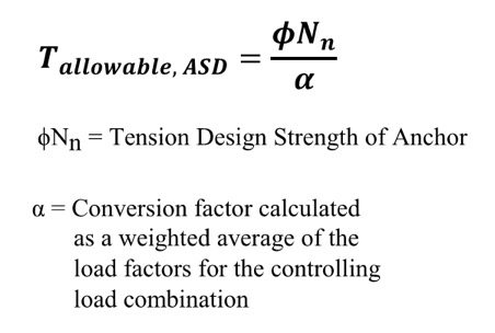 So what do you do now? Well, there is some guidance provided by ICC-ES for manufacturers to convert calculated SD capacities to ASD allowable load values. Since there is no conversion procedure stated in the IBC or referenced standards, designers may want to use this generally accepted method for converting anchor capacities designed using ACI 318. ICC-ES acceptance criteria for post-installed mechanical and adhesive anchors (AC193 and AC308) and cast-in-place steel connectors and proprietary bolts (AC398 and AC399) outline a procedure to convert LRFD capacities to ASD using a weighted average for the governing LRFD/SD load combination. So if the governing load combination for this anchor was 1.2D + 1.6L and the dead load was 1,000 pounds and the live load was 4,000, then the conversion factor would be (1.2)(0.2) + (1.6)(0.8) = 1.52 (keep in mind that the LRFD/SD capacity is divided by the conversion factor in the ICC-ES equation shown here for tension).
Right away, there are a few things that you may be thinking:
- What about load factors that may exist in ASD load combinations?
- It may just be easier to just recalculate my design loads using LRFD/SD combinations!
- The resulting allowable loads will vary based on the load type, or combination thereof.
- If the ACI 318 design strength is limited by the steel anchor, then the conversion will result in an allowable load that is different from the allowable load listed for the steel element in AISC 360.
Let’s take a look at these objections one by one.
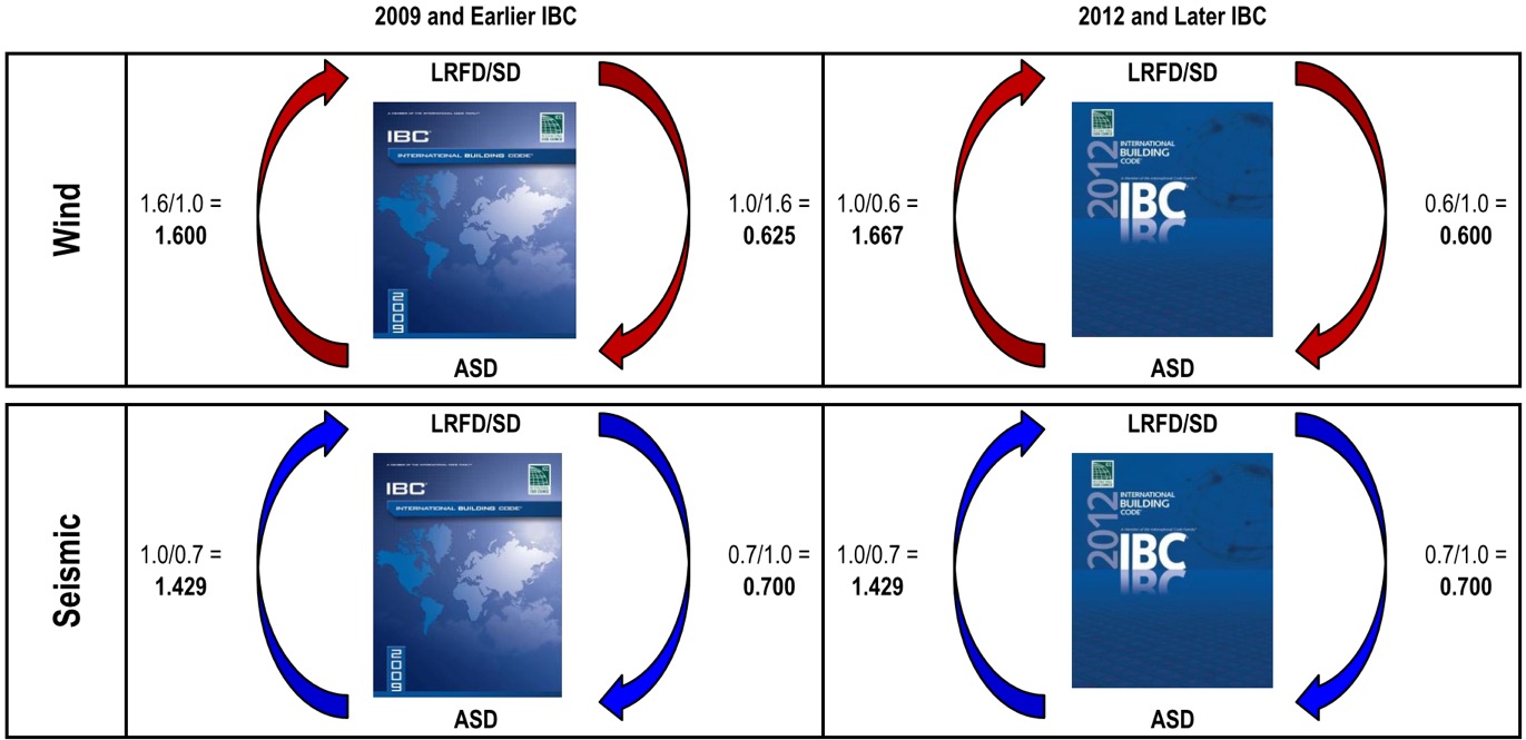
Item 1: Since unfactored earthquake loads are determined at the ultimate level in the IBC, they have an LRFD/SD load factor of 1.0 and an ASD load factor less than 1.0, which is also true for wind loads in the 2012 and 2015 IBC (see graphic below). Using the LRFD/SD load factor of 1.0 obviously does not convert the capacity from LRFD to ASD so you must also account for ASD load factors when calculating the conversion factor. To do so, instead of just using the LRFD load factor, use the ratio of LRFD Factor over ASD Factor. So if the governing load combination for an anchor was 0.9D + 1.0E and the dead load was 1,000 pounds and the seismic load was 4,000, then the conversion factor would be (0.9)(0.2) + (1.0/0.7)(0.8) = 1.32.
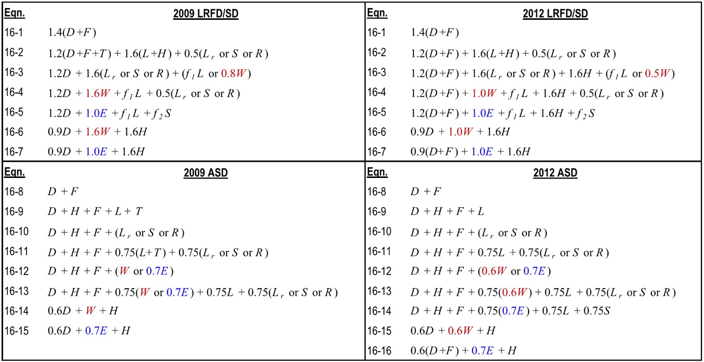
Item 2: Even though the weighted average conversion requires you to go back and dissect the demand load into its various load types, often this can be simplified. ICC-ES acceptance criteria permit you to conservatively use the largest load factor. The most common application I run into is working with ASD-level tension loads for wood shearwall overturning that must be evaluated using SD-level capacities for the concrete anchorage. Since these loads almost always consist of wind or seismic loads, using the largest factor is not overly conservative. Depending on the direction in which you are converting the demand loads or resistance capacities, the adjustment factors are as shown in the figure below. Affected Simpson Strong-Tie products now have different allowable load tables for each load type. (For examples, see pp. 33-36 of our Wood Construction Connectors catalog for wind/seismic tables and pp. 28-30 of our Anchoring and Fastening Systems catalog for static/wind/seismic tables.)
Item 3: I am unsure whether there is any sound rationale for having allowable loads for an anchor resisting 10% dead load and 90% live load differ from those of an anchor that resists 20% dead load and 80% live load. Perhaps a reader could share some insight, but I just accept it as an expedience for constructing an ASD conversion method for a material design standard that was developed for SD methodology only.
Item 4: We have differing opinions within our engineering department on how to handle the steel strength component of the various SD failure modes listed in ACI 318. Some believe all SD failure modes in ACI 318 should be converted using the load factor conversion method. I side with others who believe that the ASD capacity of a steel element should be determined using AISC 360. So when converting SD anchor tension values for a headed anchor, I would apply the conversion factor to the concrete breakout and pullout failure modes from ACI 318, but use the ASD steel strength from AISC 360.
Finally, I wanted to point out that the seismic provisions in ACI 318, such as ductility and stretch length, must be considered when designing anchors and are not always apparent when simply converting to ASD. For this reason, I usually suggest converting ASD demand loads to SD levels so you can use our Anchor Designer™ software to check all of the ACI 318 provisions. But for some quick references, we now publish tabulated ASD values for our code-listed mechanical and adhesive anchors in our C-A-2016 catalog — just be sure to read all of the footnotes!

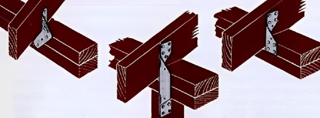
Simultaneous Loading on Hurricane Ties
“Structures are connections held together by members” (Hardy Cross)
I heard this quote recently during a presentation at the Midwest Wood Solutions Fair. I had to write it down for future reference because of course, all of us here at Simpson Strong-Tie are pretty passionate about connections. I figured it wouldn’t take too long before I’d find an opportunity to use it. So when I started to write this blog post about the proper selection of a truss-to-wall connection, I knew I had found my opportunity – how fitting this quote is!
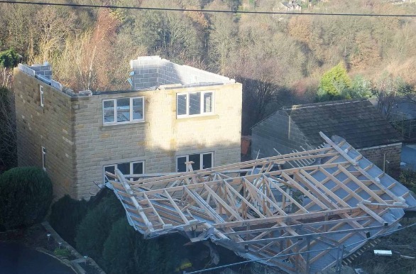
There are plenty of photos of damage wrought by past hurricanes to prove that the connection between the roof and the structure is a critical detail. In a previous blog post, I wrote about whose responsibility it is to specify a truss-to-wall connection (hint: it’s not the truss Designer’s). This blog post is going to focus on the proper specification of a truss-to-wall connection, the methods for evaluating those connections under combined loading and a little background on those methods (i.e., the fun stuff for engineers).
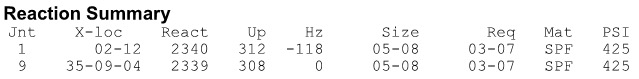
Take a quick look at a truss design drawing, and you will see a reaction summary that specifies the downward reaction, uplift and a horizontal reaction (if applicable) at each bearing location. Some people are tempted to look only at the uplift reaction, go to a catalog or web app, and find the lowest-cost hurricane tie with a capacity that meets or barely exceeds the uplift reaction.
However, if uplift was the only loading that needed to be resisted by a hurricane tie, why would we publish all those F1 and F2 allowable loads in our catalog?

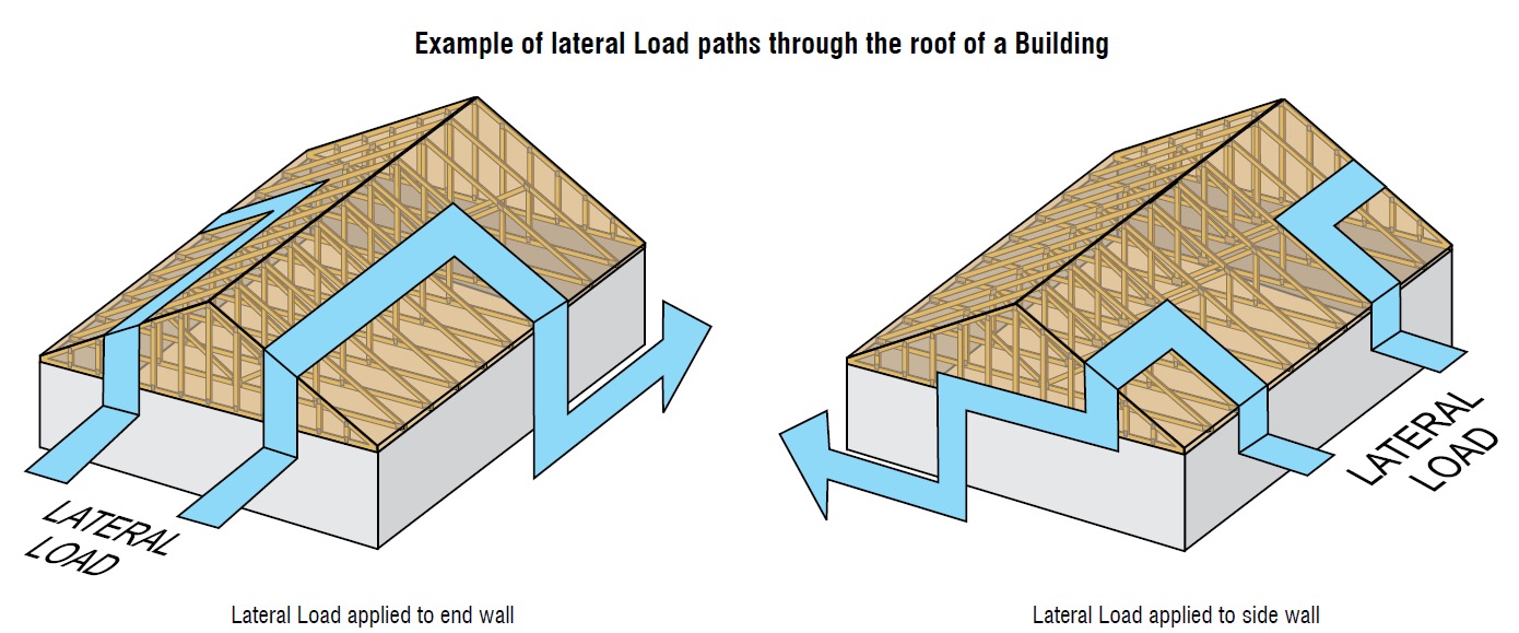
Of course, many of you know that those F1 and F2 allowable loads are used to resist the lateral loads acting on the end and side walls of the building, which are in addition to the uplift forces. Therefore, it is not adequate to select a hurricane tie based on uplift reactions alone.
Where does one get the lateral loads parallel and perpendicular to the plate which must be resisted by the truss-to-wall connection? Definitely not from the truss design drawing! Unless otherwise noted, the horizontal reaction on a truss design should not be confused with a lateral reaction due to the wind acting on the walls – it is simply a horizontal reaction due to the wind load (or a drag load) being applied to the truss profile. It is also important to note that any truss-to-wall connection specified on a truss design drawing was most likely selected based on the uplift reaction alone. There may even be a note that says the connection is for “uplift only” and does not consider lateral loads. In this case, unless additional consideration is made for the lateral loads, the use of that connector alone would be inadequate.
Say, for example, that the uplift and lateral/shear load requirements for a truss-to-wall connection are as follows:
Uplift = 795 lb.
Shear (parallel-to-wall) = 185 lb. (F1)
Lateral (perp-to-wall) = 135 lb. (F2)
Based on those demand loads, will an H10A work?
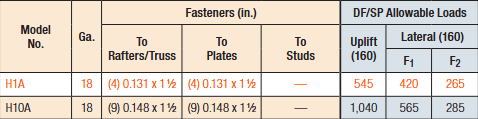
An initial look at the H10A’s allowable loads suggests it might be adequate. However, when these loads are entered into the Connector-Selector, no H10A solution is found.
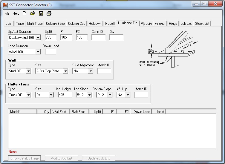
Why? Because Connector-Selector is evaluating the connector for simultaneous loading in more than one direction using a traditional linear interaction equation approach as specified in our catalog:
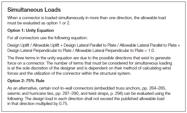
If the shear and lateral forces were to be resisted by another means, such that the H10A only had to resist the 795 lb. of uplift, then it would be an adequate connector for the job. For example, the F1 load might be resisted with blocking and RBC clips, and the F2 loads might be resisted with toe-nails that are used to attach the truss to the wall prior to the installation of the H10A connectors. However, if all three loads need to be resisted by the same connector, then the H10A is not adequate according to the linear interaction equation.

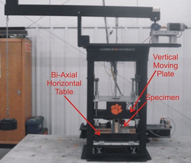
Some might question how valid this method of evaluation is – Is it necessary? Is it adequate? How do we know? And that is where the interesting information comes in. Several years ago, Simpson Strong-Tie partnered with Clemson University on an experimental study with the following primary objectives:
1. To verify the perceived notion that the capacity of the connector is reduced when loaded in more than one direction and that the linear interaction equation is conservative in acknowledging this combined load effect.
2. To propose an alternative, more efficient method if possible.
Three types of metal connectors were selected for this study – the H2.5A, H10, and the META20 strap – based on their different characteristics and ability to represent general classes of connectors. The connectors were subjected to uni-axial, bi-axial and tri-axial loads and the normalized capacities of the connectors were plotted along with different interaction/design surfaces.
These interaction plots were used to visualize and parameterize the combined load effect on the capacity of the connectors. The three different interaction plots that were examined were the traditional linear relationship, a quadratic interaction surface and a cuboid design space.
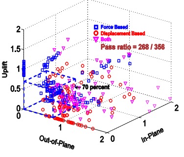
The results? Not only was the use of the linear interaction equation justified by this study, but a new, more efficient cuboid design surface was also identified. It provides twice the usable design space of the surface currently used for tri-axial loading and still provides for a safe design (and for the bi-axial case, it is even more conservative than the linear equation). This alternative method is given in our catalog as follows:

Now we can go back to the H10A and re-evaluate it using this alternative method:

As it turns out, the H10A does have adequate capacity to resist the simultaneous uplift, shear and lateral loads in this example. This just goes to show that the alternative method is definitely worth utilizing, whenever possible, especially when a connector fails the linear equation.
For more information about the study, see Evaluation of Three Typical Roof Framing-to-Top Plate/Concrete Simpson Strong-Tie Metal Connectors under Combined Loading.
What is your preferred method for resisting the combined shear, lateral and uplift forces acting on the truss-to-wall connections? Let us know in the comments below!