Shrinkage Compensation Devices

Over the weekend, I had the pleasure of watching my daughter in her cheer competition. I was amazed at all the intricate detail they had to remember and practice. The entire team had to move in sync to create a routine filed with jumps, tumbles, flyers and kicks. This attention to detail reminded me of the new ratcheting take-up device (RTUD) that Simpson Strong-Tie has just developed to accommodate 5/8″ and ¾” diameter rods. The synchronized movement of the internal inserts allows the rod to move smoothly through the device as it ratchets. The new RTUDs are cost effective and allow unlimited movement to mitigate wood shrinkage in a multi-story wood- framed building. When designing such a building, the Designer needs to consider the effect of shrinkage and how to properly mitigate it.

Our SE blog post on Continuous Rod Restraint Systems for Multi-Story Wood Structures explained the importance of load path and  the effects of wood shrinkage. This week’s blog post will focus on the importance of mitigating the shrinkage that typically occurs in multi-story light-frame buildings.

Shrinkage is natural in a wood member. As moisture reaches its equilibrium in a built environment, the volume of a wood member decreases. The decrease in moisture causes a wood-framed building to shrink.

The IBC allows construction of light-framed buildings up to 5 and 6 stories in the United States and Canada respectively. Based on the type of floor framing system, the incremental shrinkage can be up to ¼” or more per floor. In a 5-story building, that can add up to 1-¼” or more and possibly double that when construction settlement is included.
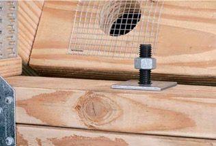
rods1
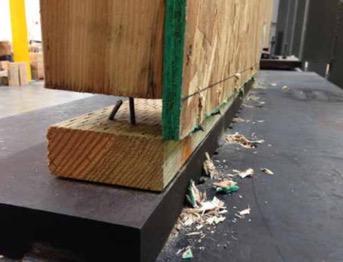
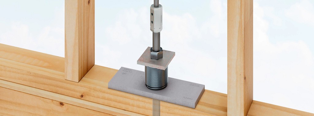
Typical Example of gap forming between nut and plate when wood shrinkage at top level occurs without shrinkage device.

The Simpson Strong-Tie Wood Shrinkage Calculator is a perfect tool to determine the total shrinkage your building can experience.
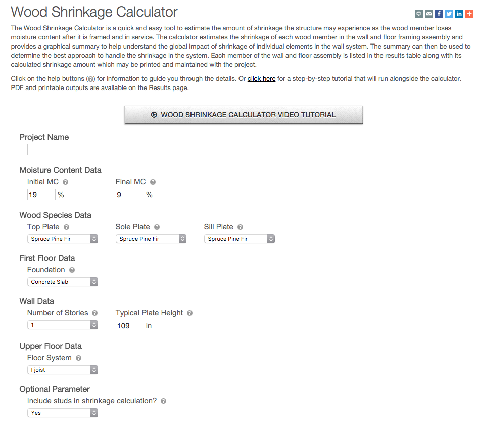
Wood Shrinkage Calculator

In order to accommodate the shrinkage that occurs in a multi-story wood-framed building, Simpson Strong-Tie offers several shrinkage compensating devices. These devices have been tested per ICC-ES Acceptance Criteria 316 (AC316) and are listed under ICC-ES ESR-2320 (currently being updated for the new RTUD5, RTUD6, and ATUD9-3).

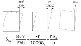
AC316 limits the rod elongation and device displacement to 0.2 inches between restraints in shearwalls. This deflection limit is to be used in calculating the total lateral drift of a light-framed wood shearwall.
rod3
3 Part Shearwall Drift Equation

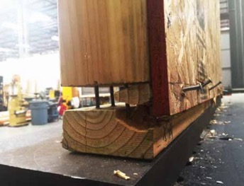
The 0.2-inch allowable limit prescribed in AC316 is important to a shearwall’s structural ability to transfer the necessary lateral loads through the structure below to the foundation level. This limit assures that the structural integrity of the nails and sill plates used to transfer the lateral loads through the shearwalls is not compromised during a seismic or wind event. Testing has shown that sill plates can crack when excessive deformation is observed in a shearwalls. Nails have also been observed to pull out during testing.  Additional information on this can be found here.
rod4
Sill Plates Cracked due to excessive uplift at ends of shearwall.
rods5
Nails pull out due to excessive uplift at ends of shearwall.

In AC316, 3 types of devices are listed.

  • Compression-Controlled Shrinkage Compensating Device (CCSCD): This type of device is controlled by compression loading, where the rod passes uninterrupted through the device. Simpson Strong-Tie has several screw-type take-up devices, such as the Aluminum Take-Up Device (ATUD) and the Steel Take-Up Device (TUD), of this type.
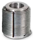
rods6
ATUD (CCSCD)
  • Tension-Controlled Shrinkage Compensating Device (TCSCD): This type of device is controlled by tension loading, where the rod is attached or engaged by the device and allows the rod to ratchet through as the wood shrinks. The Simpson Strong-Tie Ratcheting Take-Up Device (RTUD) is of this type.
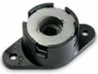
rod7
RTUD (TCSCD)
  • Tension-controlled Shrinkage Compensating Coupling Device (TCSCCD): This type of device is controlled by tension loading that connects rods or anchors together. The Simpson Strong-Tie Coupling Take-Up Device (CTUD) is of this type.
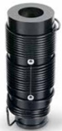
CTUD (TCSCCD)
CTUD (TCSCCD)

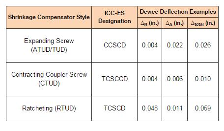
Each device type has unique features that are important in achieving the best performance for different conditions and loads. The following table is a summary of each device.
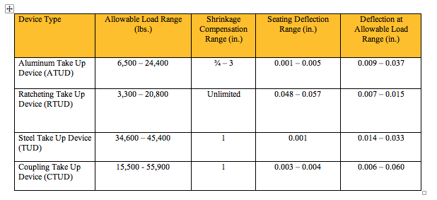
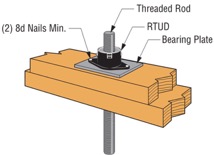
rods9The most cost-effective Simpson Strong-Tie shrinkage compensation device is the RTUD. This device has the smallest number of components and allows the rod unlimited travel through the device. It is ideal at the top level of a rod system run or where small rod diameters are used. Simpson Strong-Tie RTUDs can now accommodate 5/8″ (RTUD5) and ¾” (RTUD6) diameter rods.

How do you choose the best device for your projects? A Designer will have to consider the following during their design.
rod10
RTUD Assembly

Rod Tension (Overturning) Check:

  • Rods at each level designed to meet the cumulative overturning tension force per level
  • Standard and high-strength steel rods designed not to exceed tensile capacity as defined in AISC specification
    • Standard threaded rod based on 36 / 58 ksi (Fy/Fu)
    • High-strength Strong-Rod based on 92 / 120 ksi (Fy/Fu
    • H150 Strong-Rod based on 130 / 150 ksi (Fy/Fu)
  • Rod elongation (see below)

 Bearing Plate Check

  • Bearing plates designed to transfer incremental overturning force per level into the rod
  • Bearing stress on wood member limited in accordance with the NDS to provide proper bearing capacity and limit wood crushing
  • Bearing plate thickness has been sized to limit plate bending in order to provide full bearing on wood member

 Shrinkage Take-Up Device Check

  • Shrinkage take-up device is selected to accommodate estimated wood shrinkage to eliminate gaps in the system load path
  • Load capacity of the take-up device compared with incremental overturning force to ensure that load is transferred into rod
  • Shrinkage compensation device deflection is included in system displacement

 Movement/Deflection Check

  • System deformation is an integral design component impacting the selection of rods, bearing plates and shrinkage take-up devices
  • Rod elongation plus take-up device displacement is limited to a maximum of 0.2″ per level or as further limited by the requirements of the engineer or jurisdiction
  • Total system deformation reported for use in Δa term (total vertical elongation of wall anchorage system per NDS equation) when calculating shearwall deflection
  • Both seating increment (ΔR) and deflection at allowable load (ΔA) are included in the overall system movement. These are listed in the evaluation report ICC-ES ESR-2320 for take-up devices

 Optional Compression Post Design

  • Compression post design can be performed upon request along with the Strong-Rod System
  • Compression post design limited to buckling or bearing perpendicular to grain on wood plate
  • Anchorage design tools are available
  • Anchorage design information conforms to AC 318 anchorage provisions and Simpson Strong-Tie testing

In order to properly design a continuous rod tie-down system for your shearwall overturning restraint, all of the factors listed above will need to be taken into consideration.

A Designer can also contact Simpson Strong-Tie by going to www.strongtie.com/srs and filling out the online “Contact Us” page to have Simpson Strong-Tie design the continuous rod tie-down system for you. This design service does not cost you a dime. A few items will be required from the Designer in order for Simpson Strong-Tie to create a cost-effective rod run (it is recommended that on the Designer specify these in the construction documents):

  • There is a maximum system displacement of 0.2″ per level, which includes rod elongation and shrinkage compensation device deflection. Some jurisdictions may impose a smaller deflection limit.
  • Bearing plates and shrinkage compensation devices are required at every level.
  • Cumulative and incremental forces must be listed at each level in Allowable Stress Design (ASD) force levels.
  • Construction documents must include drawings and calculations proving that design requirements have been met. These drawings and calculations should be submitted to the Designer for review and the Authority Having Jurisdiction for approval.

More information can be obtained from our website at www.strongtie.com/srs, where a new design guide for the U.S., F-L-SRS25, and a new catalog for Canada, C-L-SRSCAN22, are available for download.

US Design Guide F-L-SRS25 and Canadian Catalog C-L-SRSCAN22

Seismic Bracing Requirements for Nonstructural Components

Have you ever been at home during an earthquake and the lights turned off due to a loss of power?  Imagine what it would be like to be in a hospital on an operating table during an earthquake or for a ceiling to fall on you while you are lying on your hospital bed.
Continue Reading

Continuous Rod Restraint Systems for Multi-Story Wood Structures

This week was our new employee Sales and Product Orientation class. Although breaking stuff is fun, my second favorite part of the class is teaching about the importance of a continuous load path. I think it is really the most important thing a Structural Engineer does. If we don’t pay attention to the loads, where they occur and create a path so they can get where they need to go, a building may not stand up. This week, we also released some new tools and information for our new Strong-Rod™ Systems, which are used to complete the load path for multi-story wood-framed shearwall overturning restraint and roof uplift restraint.

Two Load Paths

All wood-framed buildings need to be designed to resist shearwall overturning and roof-uplift forces. To transfer these tensile forces through the load path, connectors (hurricane ties, straps and holdowns) have been the traditional answer. Simpson Strong-Tie offers a few options there.  With the growth in multi-story wood-framed structures, where the code requires shrinkage to be addressed and overturning and uplift forces are typically higher, rod systems have become an increasingly popular load restraint solution. Our Anchor Tiedown System (ATS) for shearwall overturning restraint has been around for many years. A new Strong-Rod Systems Design Guide and revamped web pages provide information on new design options, components and configurations.

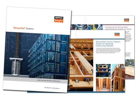
Strong-Rod Systems Seismic and Wind Restraint Systems Guide

The guide and website focus more on the unique design considerations for rod systems, how you should specify the system and highlight the design services that we provide. They also provide more detail and design information for our relatively new Uplift Restraint System (URS) for roofs. Connectors are a common choice for transferring the net roof uplift forces from wind events down the structure. Although in some high-wind areas, rod systems are preferred.

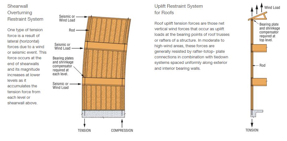
ATS and URS Continuous Rod Tiedown Systems

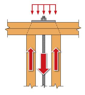
I’ll touch on some of the design considerations for these types of systems below, but back to the load path. For shearwall overturning restraint using holdowns, the load path is fairly simple. Once the lateral load is in the shearwall, the sheathing and nailing lifts up on the post. The holdown connects to the post, holding it down and transferring the forces to the foundation or level below. A continuous rod tiedown system follows a little different path. The sheathing and nailing lifts up on the boundary posts and the posts push up on the framing above until the load is resisted in bearing by a bearing plate. The load is then transferred into the rod and down to the foundation. There has been a lot of testing and research on the effects of skipping restraint locations where a bearing plate restraint is installed at every other floor or only at the top level.  Doing that will change the load path because the load has to continue to travel up until a restraint holds it down. It also negatively impacts the stiffness and drift of the shearwall stack, not to mention increases project cost because the boundary posts, rod and bearing must be sized to transfer the cumulative overturning forces from each level.

ATS load path
ATS load path

Wood Shrinkage, Take-up Devices and Displacement Limits

Shrinkage is not just a Seinfeld episode cult classic. It is also something that designers need to consider when designing wood structures. IBC Section 2304.3.3 requires that designers evaluate the impact of wood shrinkage on the building structure when bearing walls support more than two floors and a roof. The effects of wood shrinkage can impact many things in the structure from finishes to MEP systems to the continuous rod system. As the wood members lose moisture, the wood shrinks and the building settles. This can cause gaps at the bearing plate locations of continuous rod systems because the continuous steel rod doesn’t shrink. That is where the magic of take-up devices comes in. They allow the building to shrink but keep gaps from forming by filling the gap (expanding devices – can be screw style or ratcheting), ratcheting down the rod (ratcheting devices), or making the rod shrink as much as the wood (contracting coupling device).


In addition to keeping the rod system tight to ensure the intended performance, it is important to consider the movement associated with the rod system when under wind or earthquake loading. The IBC requires shearwall displacements to be within story drift limits in moderate to high seismic regions. We highlighted some of the changes coming for the evaluation of shearwall deflection in the previous post discussing the New Treatment of Shear Wall Aspect Ratios in the 2015 SDPWS. For continuous rod systems, there are some additional limits. ICC-ES AC316 Acceptance Criteria for Shrinkage Compensating Devices requires designs to limit displacement between restraints to 0.20 inches (including rod elongation and device displacement) for shearwall restraint. The movement of the take-up device plays a big part in meeting this requirement and the rod diameter required. Screw-style devices have the lowest total movement. Ratcheting devices are appropriate in many cases as well such as the upper levels where loads are lower, but may require larger rod diameters to meet the displacement limit.

figure5ICC-ES AC391 Acceptance Criteria for Continuous Rod Tie-down Runs and Continuous Rod Tie-down Systems Used to Resist Wind Uplift covers continuous rod systems for roof uplift restraint. The displacement limit for the Continuous Rod Tie-down Run (just the rod system components) is limited to 0.18 inches of rod elongation for the total length of rod. The Strong-Rod URS evaluates the Continuous Rod Tie-down System (the whole load path). Displacement limits for the system are L/240 for the top plate bending and 0.25 inches total deflection at the top plate between tie-down runs (including top plate bending, rod elongation, wood bearing deformation and take-up device displacement). The differences between the rod run and rod system analysis as well as other design considerations are explained in more detail in the design guide and on our website.

I always end my continuous load path presentation during orientation class with the same questions and if they were paying attention I get the response I want.

“What is the most important thing a Structural Engineer does?”

“Designs a continuous load path for the building!”

“What does Simpson Strong-Tie do?”

“Provides product and system solutions to help engineers do their job!”

Take a look at the new Strong-Rod Systems tools and information and let us know how we can help you with your next multi-story wood-framed project.

What related blog topics would you like to discuss? Let us know in the comments below.

Which Tornado Saferoom is Right for You?

tornado1
Image courtesy of FLASH.

There certainly seems to be increased awareness of the potential for damage and injury from tornadoes these days. Recent information published by the Federal Emergency Management Agency (FEMA) and the Federal Alliance for Safe Homes (FLASH) help explain that. This increased awareness has led to a growing interest in tornado shelters for protection of life and property.

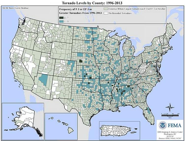
This FEMA graphic shows that most areas of the United States have been affected by a tornado at some point since 1996, and many have been affected by one or more strong tornadoes (EF3 or greater).

Figure 1 - Tornado activity by county: 1996-2013
Figure 1 – Tornado activity by county: 1996-2013

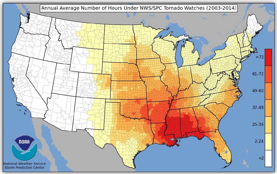
Living in North Texas near the Simpson Strong-Tie manufacturing plant in McKinney, Texas, I know all too well the sinking feeling of hearing the tornado sirens and turning on the TV to find you are under a tornado watch. FLASH recently published a graphic developed by the National Weather Service that shows the large number of U.S. counties that have been under a tornado watch between 2003-2014, and the high number of warnings that some counties experienced.

Figure 2 - Annual average number of hours under NWS/SPC tornado watches (2003-2014)
Figure 2 – Annual average number of hours under NWS/SPC tornado watches (2003-2014)

Other than moving to an area that has fewer tornadoes, one of the best ways to protect your family and at least have more peace of mind during tornado season is to have a tornado shelter or safe room. These structures are designed and tested to resist the highest winds that meteorologists and engineers believe occur at ground level during a tornado and the debris that is contained in tornado winds.

Tornado shelters can be either pre-fabricated and installed by a specialty shelter manufacturer, or can be site-built from a designed plan or pre-engineered plan. A good source for information on pre-fabricated shelters is the National Storm Shelter Association, a self-policing organization that has strict requirements for the design, testing and installation of its members’ shelters.

FEMA publishes a document, P-320, Taking Shelter from the Storm, that provides good information on safe rooms in general, as well as several pre-engineered plans for tornado safe rooms.

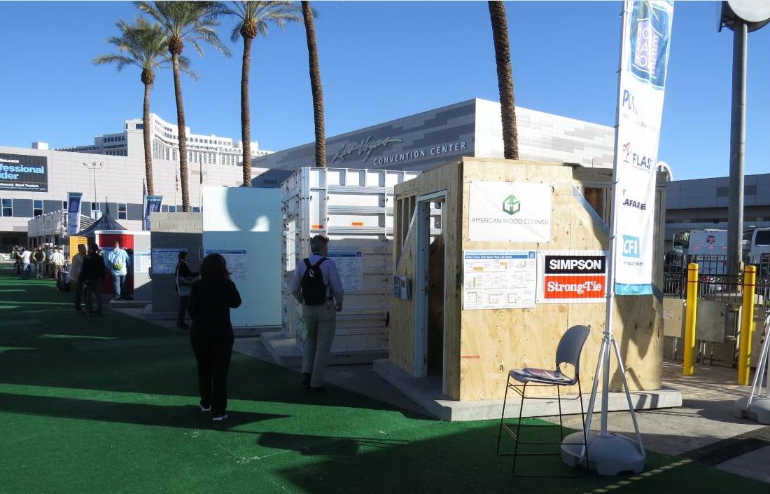
To highlight the different types of safe rooms covered by FEMA P-320, FEMA, FLASH and the Portland Cement Association (PCA) sponsored an exhibit at January’s International Builder’s Show. The exhibit was called the “Home Safe Home Tornado Saferoom Showcase.” It featured six different types of saferooms that builders could incorporate into the homes they build. Simpson Strong-Tie and the American Wood Council collaborated to build a wood frame with steel sheathing safe room meeting the FEMA P-320 plans. Other safe rooms shown at the exhibit included pre-cast concrete and pre-manufactured steel shelters manufactured by NSSA members, and reinforced CMU, ICF cast-in-place concrete and aluminum formed cast-in-place concrete built to FEMA P-320 plans.

Figure 4 - Home Safe Home Tornado Saferoom Showcase
Figure 4 – Home Safe Home Tornado Saferoom Showcase

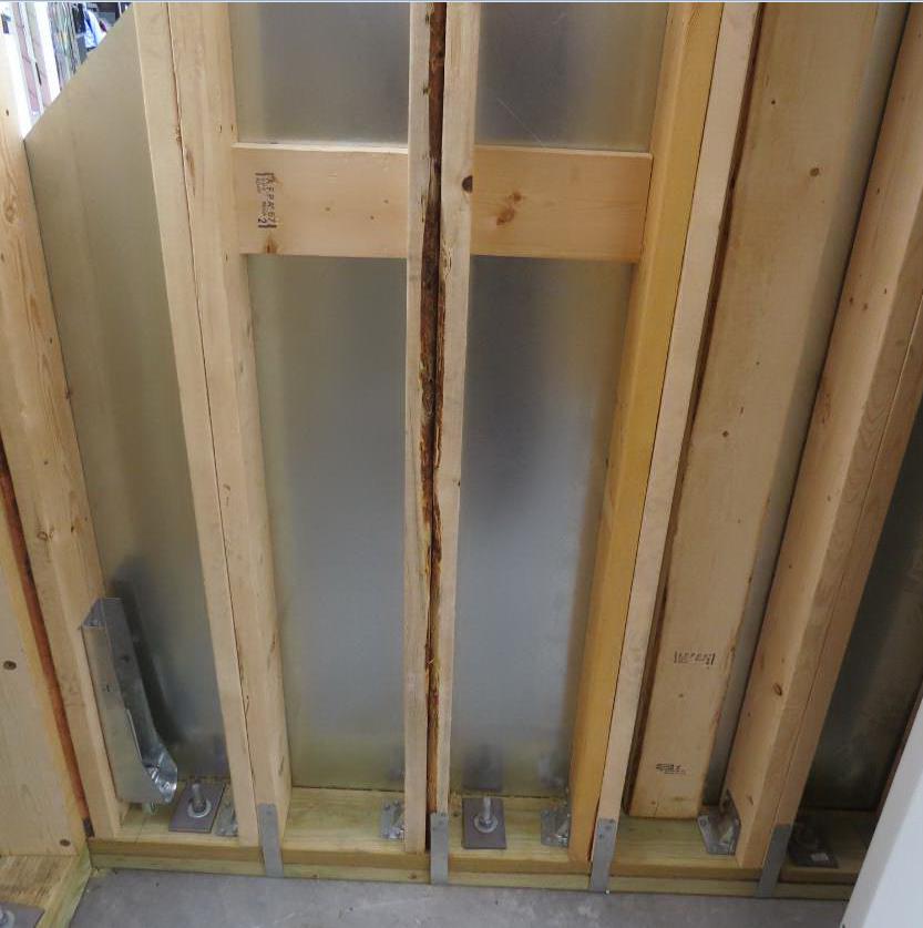
Simpson Strong-Tie staff in McKinney, Texas, constructed the wood frame/steel sheathing safe room in panels and shipped it to the show. It was built from locally sourced lumber, readily available fasteners and connectors and sheets of 16 ga. steel (which we happen to keep here at the factory). It had cut-away sheathing at the corners to show the three layers of sheathing needed. Our message to builders was that this type of shelter would be the easiest for their framers to build on their sites.

tornado5
Figure 5: Holdowns and plate anchorage
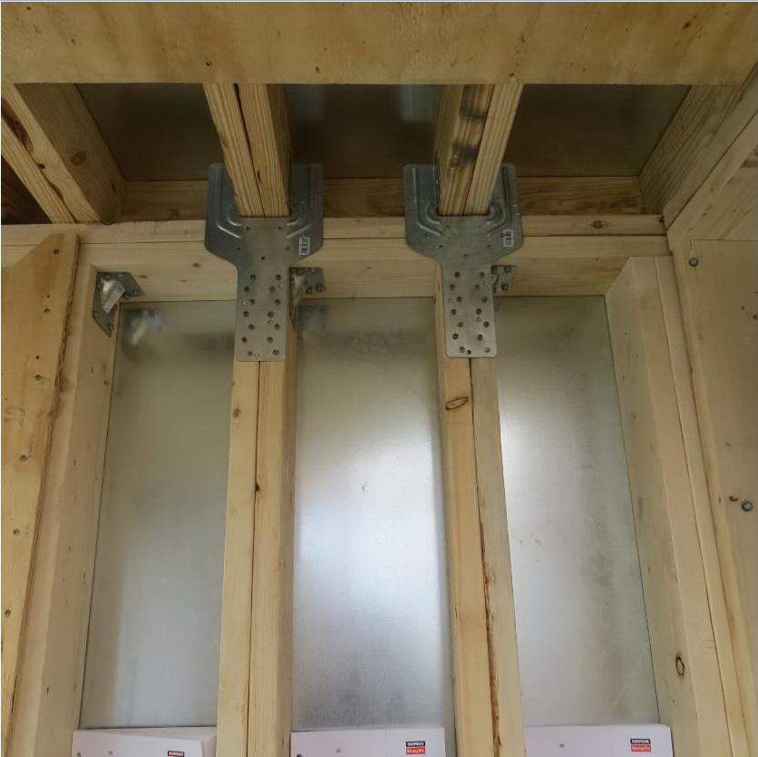
tornado6
Figure 6: Roof-to-wall connections
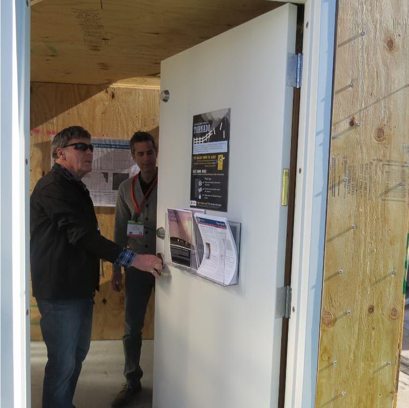
tornado7
Figure 7: A visitor examines our tested door, a vital component of any shelter. This one was furnished by CECO Doors.

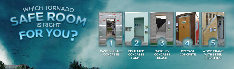
The sponsors of the exhibit took advantage of the variety of safe rooms in one place to film a video series, “Which Tornado Safe Room is Right for You?” The videos are posted at the FLASH StrongHomes channel on YouTube. The series provides comparative information on cast-in-place, concrete block masonry, insulated concrete forms, precast concrete and wood-frame safe rooms, with the goal of helping consumers to better understand their tornado safe room options.

“Today’s marketplace offers an unprecedented range of high-performing, affordable options to save lives and preserve peace of mind for the millions of families in the path of severe weather,” said FLASH President and CEO Leslie Chapman-Henderson. “These videos will help families understand their options for a properly built safe room that will deliver life safety when it counts.”

FLASH released the videos earlier this month as part America’s PrepareAthon!, a grassroots campaign to increase community emergency preparedness and resilience through hazard-specific drills, group discussions and exercises. The overall goal of the program is to get individuals to understand which disasters could happen in their community, know what to do to be safe and mitigate damage from those disasters, take action to increase their preparedness, and go one step farther by participating in resilience planning for their community. Currently, the program focuses on preparing for the disasters of tornadoes, hurricanes, floods, wildfires, earthquakes and winter storms.

Do you know what the risk of disasters is in your community? If you are subject to tornado risk, would you like to build your own safe room, have one built to pre-engineered plans or buy one from a reputable manufacturer? Let us know in the comments below.

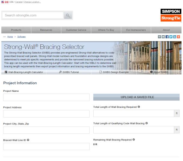
Strong-Wall Bracing Selector: Bridging the Gap between Engineered Design and Prescriptive Construction

Asking a structural engineer to design wall bracing under the IRC® can be like asking a French pastry chef to bake a cake using Betty Crocker’s Cookbook. The temptation is to toss out the prescriptive IRC recipe and design the house using ASCE 7 loads and the AWC SDPWS shear wall provisions per the IBC®. But if only a portion of the house needs to be engineered, there may be an easier option.

The prescriptive IRC states an IBC engineered design “is permitted for all buildings and structures and parts thereof” but the design must be “compatible with the performance of the conventional framed system.” But how exactly does an IRC braced wall panel perform? The code doesn’t come right out and tell us, but there are two bracing methods that are essentially shear walls masquerading as braced wall panels: Method ABW and Method BV-WSP. Backing into their allowable loads gives us the key to determining equivalence and eliminates the need to develop lateral forces.

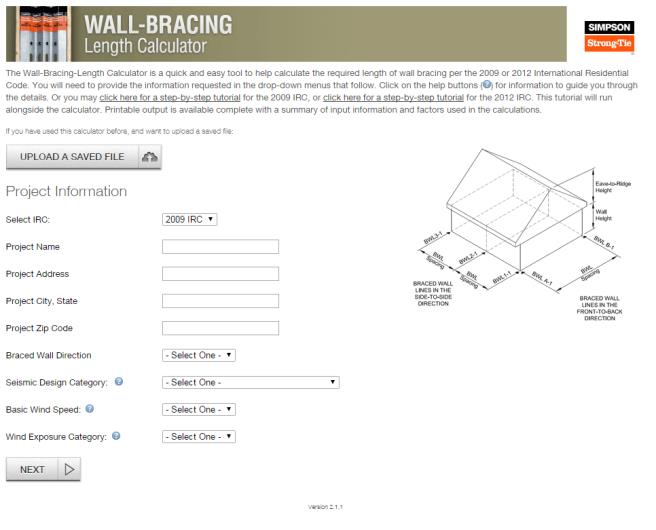
But before you can bust out the slide rule and start crunching numbers, you need to figure out how much bracing the prescriptive code requires. We developed our Wall-Bracing-Length Calculator in 2010 to help designers do just that. And last month, we launched our Strong-Wall® Bracing Selector tool to make it easier to specify equivalent solutions for tricky situations.

Strong-Wall Bracing Selector
Wall-Bracing-Length Calculator

You can export the required lengths (and project information) from the Wall-Bracing-Length Calculator directly into the Strong-Wall Bracing Selector or you can manually enter in the required lengths. The selector app will provide a list of Strong-Wall panels that have an equivalent length, evaluate their anchorage loads and return a list of pre-engineered anchor solutions for a variety of foundation types.

If you’re familiar with our Strong-Wall Prescriptive Design Guide (T-SWPDG10), the selector automates this 84-page document in just a few steps. One big upgrade is the ability to select a solution to meet the exact amount of bracing that is required. If you needed 2.8-ft. of wall bracing, you have to round up to the tabulated 4-ft. solutions if you are using the guide, but now you can select a wall solution that is equivalent to 2.8-ft., which might mean a smaller wall width or better anchor options. You also have the ability to save the selector file for later modifications, create a PDF of the job-specific output, or email the PDF directly from the program.

Strong-Wall Prescriptive Design Guide

So next time you get asked to “design” some wall bracing, see if our Wall-Bracing-Length Calculator and Strong-Wall Bracing Selector might save you some time. There is a tutorial and a design example on the Bracing Selector web page, but it’s very easy to use so you may just want to dive right in. I should also point out that the Strong-Wall SB panels have not yet been implemented into the program, but bracing information for them is available on strongtie.com in posted letters for wind (L-L-SWSBWBRCE14), seismic (L-L-SWSBSBRCE14), and seismic with masonry veneer (L-L-SWSBVBRCE14).

Let us know what you think of this new tool in the comments below.


Steel Strong-Wall® Footings Just got a Little Slimmer!

While 54 inches is a good height and will get you on most amusement park rides, what about this dimension for the width of a footing? We did some tests recently — actually a lot of tests — that answered that question.

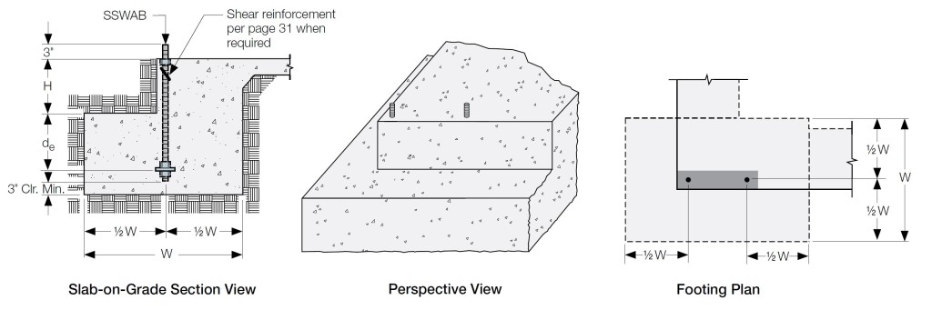
Steel Strong-Wall® narrow panels are great for resisting high seismic or wind loads, but due to their narrow widths, their resulting anchor uplift forces can be rather hefty, requiring very large pad footings. How large? For Seismic Design Categories C-F, the largest cracked concrete solution per ACI318-11 Appendix D has a width of 54 inches and an effective embedment depth of 18 inches in order to ensure the anchor remains ductile. The overall length of this footing, as seen in Figure 1, can be up to 132 inches. While purely code driven, these solutions have historically presented challenges in the field. Most concrete contractors have to dig footings this size by hand. This often leads to discussions with their engineers about finding a better solution.

Figure 1: Slab-on-Grade Installation (Traditional Solution)

Simpson Strong-Tie has been studying cast-in-place anchorage extensively in recent years. Our research has been featured in a couple of blog posts: The Anchorage to Concrete Challenge – How Do You Meet It? and Podium Anchorage – Structure Magazine. Concrete podium slab anchorage was a multi-year test program that started with grant funding from the Structural Engineers Associations of Northern California for initial concept testing at Scientific Construction Laboratories Inc. and wrapped up with full-scale detailed testing completed at the Simpson Strong-Tie Tye Gilb Laboratory in Stockton, California. This joint venture studied the performance of anchorage reinforcement into thin podium deck slabs (10-14 inch) to resist the high overturning forces of continuous rod systems on 4-5-story mid-rise construction. The testing confirmed the need to comply with Appendix D requirements to prevent plastic hinging at anchor locations. Be on the lookout for an SE Blog post on that topic in the near future. Armed with what we learned, we decided to develop tested anchor reinforcing solutions for the Steel Strong-Wall.

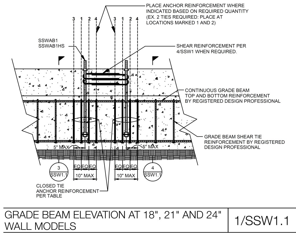
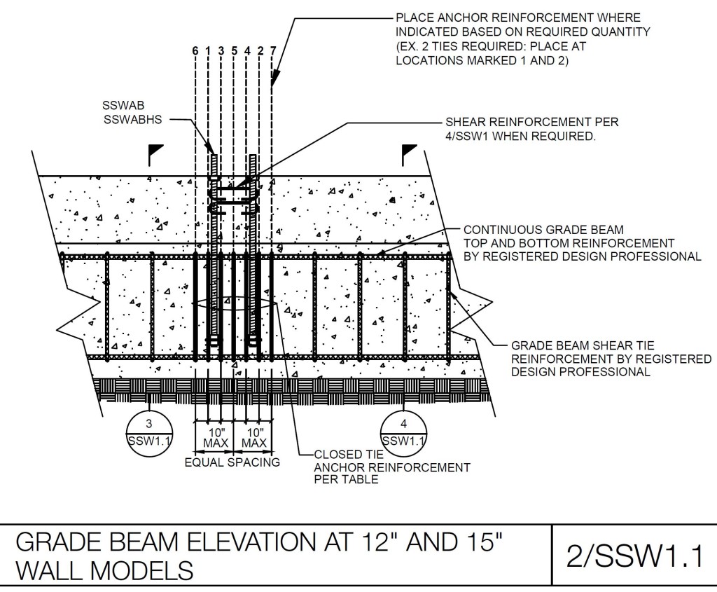
The newly developed anchor reinforcement solutions for grade beams are calculated in accordance with ACI318 Appendix D and tested to validate performance. Anchor reinforcement isn’t a new concept, as it’s been in ACI318 for some time. Essentially, anchor reinforcements transfer load from the anchor bolt to the reinforcing, which restrains the breakout cone from occurring. For the new grade beam details, the additional ties near the anchor are designed to resist the load from the anchor and are developed into the grade beam. The new details offer solutions with widths as narrow as 18 inches when anchor reinforcement is used.

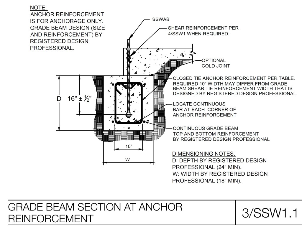
Two details have been developed: one for the larger panels (SSW18, SSW21, SSW24) as shown in Detail 1/SSW1.1, and one for the smaller panels (SSW12, SSW15) as shown in Detail 2/SSW1.1. The difference between the two is the number of anchor reinforcement ties specified in Detail 3/SSW1.1. For SSW18, SSW21 and SSW24 panels (Detail 1/SSW1.1), the total number of reinforcement per anchor is specified. Due to their smaller sizes, the anchor reinforcement ties specified in Detail 2/SSW1.1 for the SSW12 and SSW15 panels are the total required per panel.

Detail 1/SSW1.1
Detail 1/SSW1.1
Detail 2/SSW1.1
Detail 2/SSW1.1
Detail 3/SSW1.1
Detail 3/SSW1.1

Validation Testing

From the concrete podium deck anchorage test program, we discovered that the flexural and shear capacity of the slab is critical to anchor performance and must be designed to exceed the demands created by the attached structure. For grade beams, this also holds true. In wind-load applications, this demand includes the factored demand from the Steel Strong-Wall. In seismic applications, our testing and analysis showed that achieving the anchor performance expected by Appendix D design methodologies requires the concrete member design strength to resist the amplified anchor design demand from Appendix D Section D.3.3.4.3.

Validation testing was conducted to evaluate this concept. The test program consisted of a number of specimens with different configurations, including:

  • Closed tie anchor reinforcement
  • Non-closed tie u-stirrup anchor reinforcement
  • Control specimen without anchor reinforcement

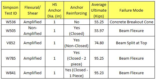
Flexural and shear reinforcement were designed to resist Appendix D amplified anchorage forces and were compared to test beams designed for non-amplified strength level forces. The results of the testing are shown in Figure 2. In the higher Seismic Design Categories (C-F), the anchor assembly must be designed to satisfy Section D.3.3.4.3 in ACI318-11 Appendix D. In accordance with D.3.3.4.3 (a), the concrete breakout strength needs to be greater than 1.2 times the nominal steel strength of the anchor, 1.2NSA. This requires a concrete breakout strength of 87 kips for a Steel Strong-Wall that uses a 1-inch high-strength anchor.

Figure 2: Steel Strong-Wall Grade Beam Testing

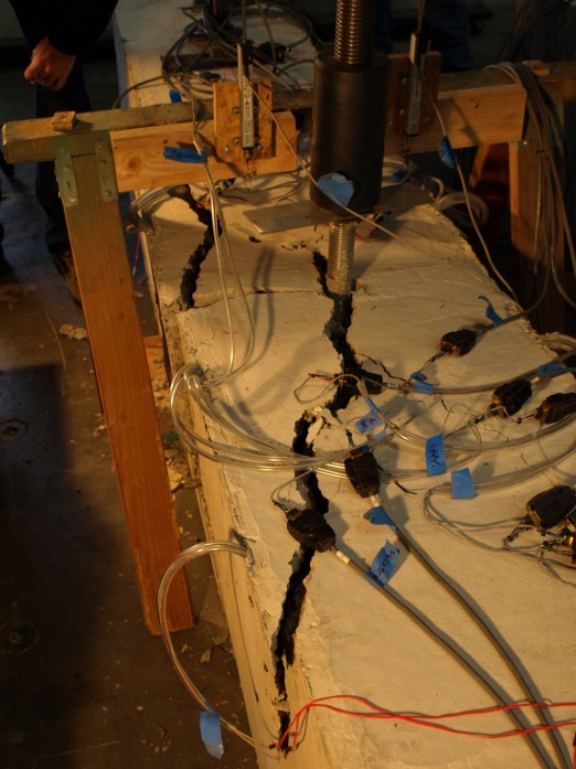
Grade beams without the anchor reinforcement detail and with flexural and shear reinforcement designed to the Appendix D amplified anchorage forces performed similar to those with closed-tie anchor reinforcement and flexural and shear reinforcements designed to the non-amplified strength level forces. Both, however, came up short of the necessary forces required by Section D.3.3.4.3 (a). From Test V852, we discovered that even though the flexural and shear reinforcement were designed with the amplified forces, the non-closed tie u-stirrups did not ensure the intended performance. From observation, the u-stirrups do not provide adequate confinement of the concrete and tend to open up under loading conditions, resulting in splitting of the beam at the top as can be seen in the photo.

Test V852: Non-Closed U-Stirrups

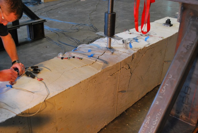
Tests W785 and W841 resulted in the best performance. Both test specimens contained flexural and shear reinforcement designed for the amplified forces, as well as closed-ties. Two configurations were tested to study their performance — two piece closed-tie anchor reinforcement in W785 and a single piece closed-tie anchor reinforcement in Test W841. As seen in Figure 2, their performance was very similar, and met the requirements of Section D.3.3.4.3 (a). The closed-ties helped confine the concrete near the top of the beam, allowing the assembly to reach the expected performance load (See the photo below). It’s important to indicate the following specifics in the New Grade Beam Anchor Reinforcement Details:

  • Anchor Reinforcement is #4 closed-ties
  • SSWAB embedment depth is 16″ +/- ½” (as shown in Detail 3/SSW1.1). This is to ensure there is enough development length of the anchor reinforcement on both sides of the theoretical breakout surface as required by ACI318-11 D.5.2.9.
  • The minimum distances from the anchor bolt plate washer to top and bottom of closed tie reinforcement are 13 inches and 5 inches respectively to ensure proper development above and below the concrete breakout cone (refer to Detail 3/SSW1.1).
  • The spacing between the two vertical legs of the anchor reinforcement tie must be 10 inches apart. While this may differ from your shear reinforcement elsewhere in the grade beam, it ensures the reinforcement is located close enough to the anchor and adequate development length is provided.
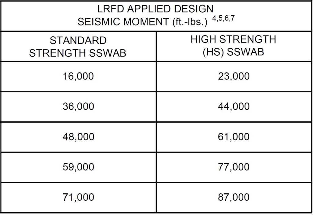
  • Flexural reinforcement (top and bottom) and shear reinforcement (ties throughout the grade beam length) are per the designer. Simpson Strong-Tie has provided information in Detail 3/SSW1.1 for the applicable minimum LRFD Applied Design Seismic Moment (See Figure 3) to make sure the grade beam design will at least resist the applied anchor forces. Project design loads not related to the Strong-Wall panel also should be considered and could control the grade beam design.
Closed-Tie Anchor Reinforcement
Figure 3: LRFD Applied Design Seismic Moment

Simpson Strong-Tie is interested in hearing your thoughts on the new details. What is your opinion? How have the new details been received on your job sites?

New Treatment of Shear Wall Aspect Ratios in the 2015 SDPWS

This post was co-written by Simpson Engineer Randy Shackelford and AWC Engineer Phil Line.

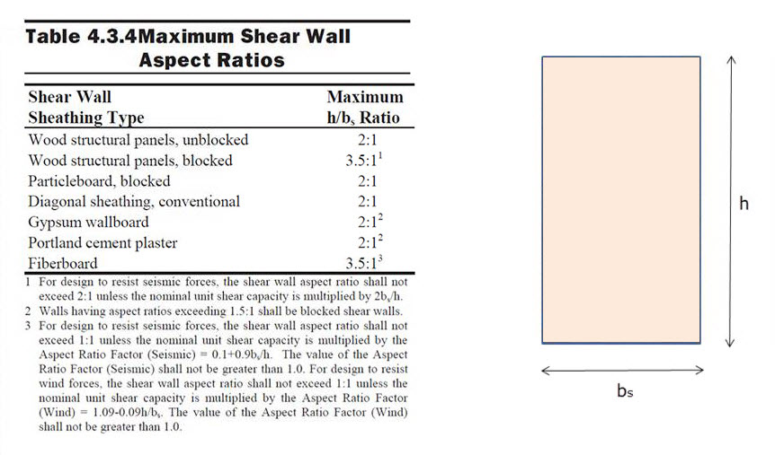
The 2015 International Building Code references a newly updated 2015 Edition of the American Wood Council Special Design Provisions for Wind and Seismic standard (SDPWS). The updated SDPWS contains new provisions for design of high aspect ratio shear walls. For wood structural panels shear walls, the term high aspect ratio is considered to apply to walls with an aspect ratio greater than 2:1. These same high‑aspect‑ratio shear wall provisions have been maintained in subsequent editions of SDPWS, including the 2021 SDPWS, and remain part of current design practice.

Figure 1. SDPWS 2008 Table 4.3.4 and illustration of shear wall with height, h and length, bs

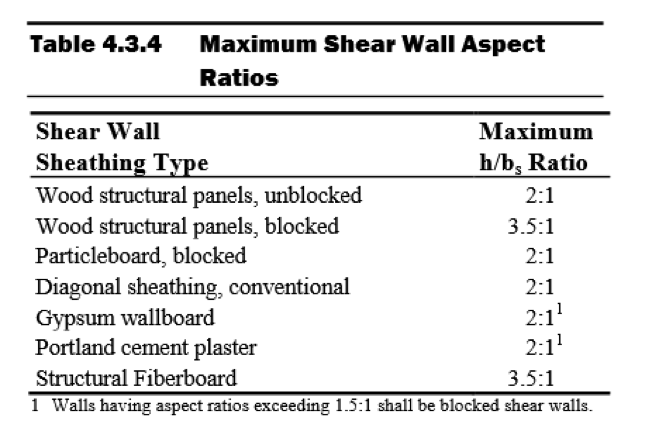
In the 2015 SDPWS, reduction factors for high aspect ratio shear walls are no longer contained in the footnotes to Table 4.3.4 (See Figure 2). Instead, these factors are included in new provisions accounting for the reduced strength and stiffness of high aspect ratio shear walls.

Figure 2. SDPWS 2015 Table 4.3.4

Deflection Compatibility – Calculation Method

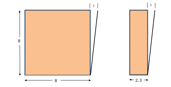
New Section 4.3.3.4.1 states that “Shear distribution to individual shear walls in a shear wall line shall provide the same calculated deflection, δsw, in each shear wall.” Using this equal deflection calculation method for distribution of shear, the unit shear assigned to each shear wall within a shear wall line varies based on its stiffness relative to that of the other shear walls in the shear wall line. Thus, a shear wall having relatively low stiffness, as is the case of a high aspect ratio shear wall within a shear wall line containing a longer shear wall, is assigned a reduced unit shear (see Figure 3).

Figure 3. Illustration of deflection compatibility


In addition, Section 4.3.4.2 contains a new aspect ratio factor, 1.25 – 0.125h/bs, that specifically accounts for the reduced unit shear capacity of high aspect ratio shear walls. The strength reduction varies linearly from 1.00 for a 2:1 aspect ratio shear wall to 0.81 for a 3.5:1 aspect ratio shear wall. Notably, this strength reduction applies for shear walls resisting either seismic forces or wind forces. For both wind and seismic, the controlling unit shear capacity is the smaller of the values from strength criteria of 4.3.4.2 or deflection compatibility criteria or 4.3.3.4.1.

Deflection Compatibility – 2bs/h Adjustment Factor Method

The 2bs/h factor, previously addressed by footnote 1 of Table 4.3.4, is now an alternative to the equal deflection calculation method of 4.3.3.4.1 and applies to shear walls resisting either wind or seismic forces. This adjustment factor method allows the designer to distribute shear in proportion to shear wall strength provided that shear walls with high aspect ratio have strength adjusted by the 2bs/h factor. The strength reduction varies linearly from 1.00 for 2:1 aspect ratio shear walls to 0.57 for 3.5:1 aspect ratio shear walls. This adjustment factor method provides roughly similar designs to the equal deflection calculation method for a shear wall line comprised of a 1:1 aspect ratio wall segment in combination with a high aspect ratio shear wall segment.

In prior editions of SDPWS, a common misunderstanding was that the 2bs/h factor represented an actual reduction in unit shear capacity for high aspect ratio shear walls as opposed to a reduction factor to account for stiffness compatibility. The actual reduction in unit shear capacity of high aspect ratio shear walls is represented by the factor, 1.25 – 0.125h/bs, as noted previously. The 2bs/h factor is the more severe of the two factors and is not applied simultaneously with the 1.25-0.125h/bs factor.

What are the major implications for design?

  • For seismic design, the 2bs/h factor method continues unchanged, but is presented as an alternative to the equal deflection method in 4.3.3.4.1 for providing deflection compatibility. The equal deflection calculation method can produce both more and less efficient designs that may result from the 2bs/h factor method depending on the relative stiffness of shear walls in the wall line. For example, design unit shear for shear wall lines comprised entirely of 3.5:1 aspect ratio shear walls can be as much as 40% greater (i.e. 0.81/0.57=1.42) than prior editions if not limited by seismic drift criteria.
  • For wind design, high aspect ratio shear wall factors apply for the first time. For shear walls with 3.5:1 aspect ratio, unit shear capacity is reduced to not more than 81% of that used in prior editions. The actual reduction will vary by actual method used to account for deflection compatibility.
  • The equal deflection calculation method is sensitive to many factors in the shear wall deflection calculation including hold-down slip, sheathing type and nailing, and framing moisture content. The familiar 2bs/h factor method for deflection compatibility is less sensitive to factors that affect shear wall deflection calculations and in many cases will produce more efficient designs.

As the 2015 International Building Code is adopted in various jurisdictions, designers will need to be aware of these new requirements for design of high aspect ratio shear walls. The 2015 SDPWS also contains other important revisions that designers should pay attention to. The American Wood Council provides a read-only version of the standard on their website that is available free of charge.

Please contribute your thoughts to these new requirements in the comments below.

What Factors Contribute To A “Resilient” Community?

The world has seen many increasingly catastrophic natural disasters in the past decade, including Hurricane Katrina (Category 3) striking New Orleans in 2005, 2010’s 7.0 magnitude Haiti and 8.8 magnitude Chili earthquakes, the 9.0 magnitude Japan earthquake along with the Christchurch earthquake (6.3 magnitude) in 2011, the tornado outbreak in 2011 which included an EF4 striking Tuscaloosa, AL and a multiple-vortex EF5 striking Joplin, MO. We also saw Category 2 Hurricane Sandy, the largest Atlantic hurricane on record in 2012 and the EF5 tornado striking Moore, Oklahoma in 2013.

Continue Reading

Resilience by Design: City of Los Angeles Lays Out a Seismic Safety Plan

“From a seismological standpoint, Northridge was not a big earthquake.” This is first sentence of the “Resilience by Design” report by L.A. Mayor’s Seismic Safety Task Force led by Dr. Lucy Jones of the U.S. Geological Survey (USGS). The report is the culmination of a year-long investigation into the greatest vulnerabilities of the city from a major seismological event. Continue Reading

Seismic Safety Regulations and Solutions

I have a special place in my heart for old buildings. Every college design course I took was related to new design. Concrete, steel, or wood design, the design problem was invariably part of a new building. I thought structural engineers designed new buildings. When I showed up for my first day of work wearing dress pants, a button-down shirt and a tie, I was handed a flashlight, tape measure, a clipboard and a Thomas Guide map (no Google maps back then) and sent to do as-built drawings for a concrete tilt-up that we were retrofitting.

When I was designing buildings, I created a lot of as-built drawings. Figuring out how a building was put together, what the structural system was (or wasn’t!) and designing a lateral load path in these old, and often historic buildings, was immensely satisfying. Knowing that history, it should not be surprising I have done a number of blog posts related to seismic retrofits. Soft-Story Retrofits, San Francisco’s Soft-Story Retrofit Ordinance, Remembering Loma Prieta, Resilient Communities, FEMA P-807, and Home Seismic Retrofit (there are probably a couple I forgot).

This week, Los Angeles Mayor Eric Garcetti proposed new seismic safety regulations . The recommendations are to retrofit soft-story wood-framed buildings within five years and older concrete buildings within 30 years. While these are only recommendations, it is encouraging to see politicians supporting policies to promote resiliency and life safety.

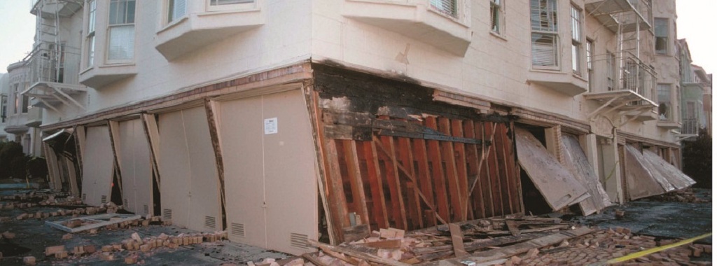
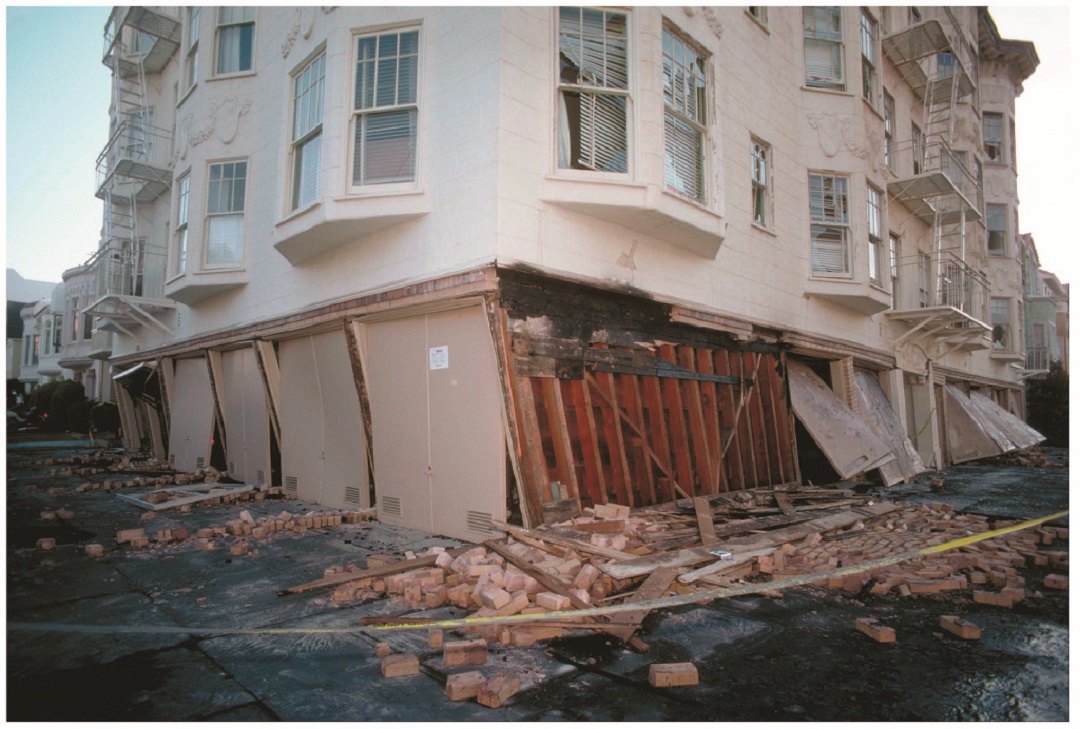
In San Francisco, thousands of building owners are already required by law to seismically retrofit multi-unit (at least five) soft-story, wood-frame residential structures that have two or more stories over a “soft” or “weak” story. These buildings typically have parking or commercial space on the ground floor with two or more stories above. As a result, the first floor has far more open areas of the wall than it actually has sheathed areas, making it particularly vulnerable to collapse in an earthquake.

Photo credit: J.K. Nakata and the U.S. Geological Survey

San Francisco’s ordinance affects buildings permitted for construction before Jan. 1, 1978. Mandatory seismic retrofit program notices requiring that buildings be screened were sent out in September, 2013, to more than 6,000 property owners. It is anticipated that approximately 4,000 of those buildings will be required to be retrofitted by 2020.

“When we look at the demographic of these buildings, they house approximately 110,000 San Franciscans. It’s paramount that we have housing for people after a disaster. We know we will see issues in all types of buildings, but this is an opportunity for us to be able to retrofit these buildings while keeping an estimated 1100,000 San Franciscans in their homes and, by the way of retrofit, allowing them to shelter in place after a disaster,” according to Patrick Otellini, San Francisco’s chief resilience officer and director of the city’s Earthquake Safety Implementation Program. “This exponentially kick starts the city’s recovery process.”

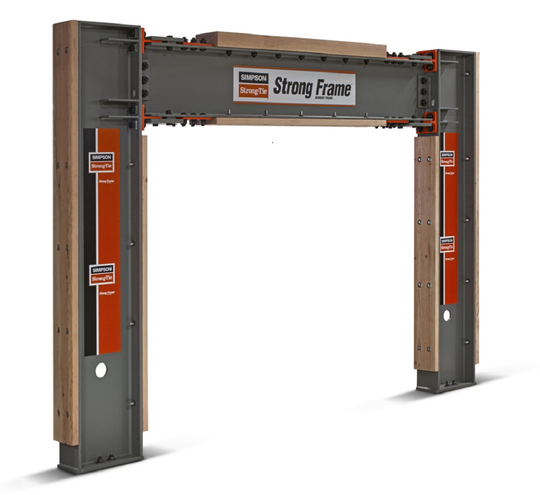
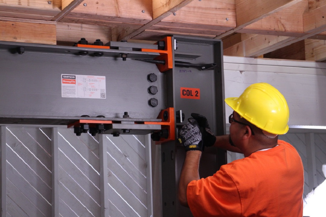
One solution to strengthen such buildings is the Simpson Strong-Tie® Strong Frame® special moment frame. Its patented Yield-Link™ structural fuses are designed to bear the brunt of lateral forces during an earthquake, isolating damage within the frame and keeping the structural integrity of the beams and columns intact.

Simpson Strong-Tie® Strong Frame® special moment frame

“The structural fuses connect the beams to the columns. These fuses are designed to stretch and yield when the beam twists against the column, rather than the beam itself, and because of this the beams can be designed without bracing. This allows the Strong Frame to become a part of the wood building and perform in the way it’s supposed to,” said Steve Pryor, S.E., International Director of Building Systems at Simpson Strong-Tie. “It’s also the only commercially-available frame that bolts together and has the type of ductile capacity that can work inside of a wood-frame building.”

Installation of the Simpson Strong-Tie® Strong Frame® special moment frame

Another key advantage of the Simpson Strong-Tie special moment frame is no field welding is required, which eliminates the risk of fire in San Francisco’s older wood-framed buildings.

To learn more about San Francisco’s retrofit ordinance, watch a new video posted on strongtie.com/softstory. For more information about the Strong Frame special moment frame, visit strongtie.com/strongframe.