Wood Shear Wall Design Example

Two weeks ago, I had the chance to present to the Young Members Group of the Structural Engineering Association of Metro Washington on the topic of Multi-Story Light-Frame Shear Wall Design. With all of the large firms in the D.C. area, it wasn’t a big surprise to find out that only about one-third of the group had experience with light-frame shear wall design.

However, while researching civil/structural engineering programs in the Midwest and Northeast last week (for our Structural Engineering/Architecture Student Scholarship program), I was disappointed to find that only about a quarter of the top engineering programs offer a wood design course. So I thought it might be helpful to post a wood shear wall design example this week.

The example is fairly basic but includes an individual full‑height and perforated shear wall analysis for the same condition. The design is based on wind loading and SPF framing, both common in the Midwest and Northeast, and follows the provisions and terminology of the 2021 Special Design Provisions for Wind and Seismic (SDPWS), which represent current practice for wood lateral system design.

Multi-Story Shear Wall Example: Wind Loads with SPF Framing

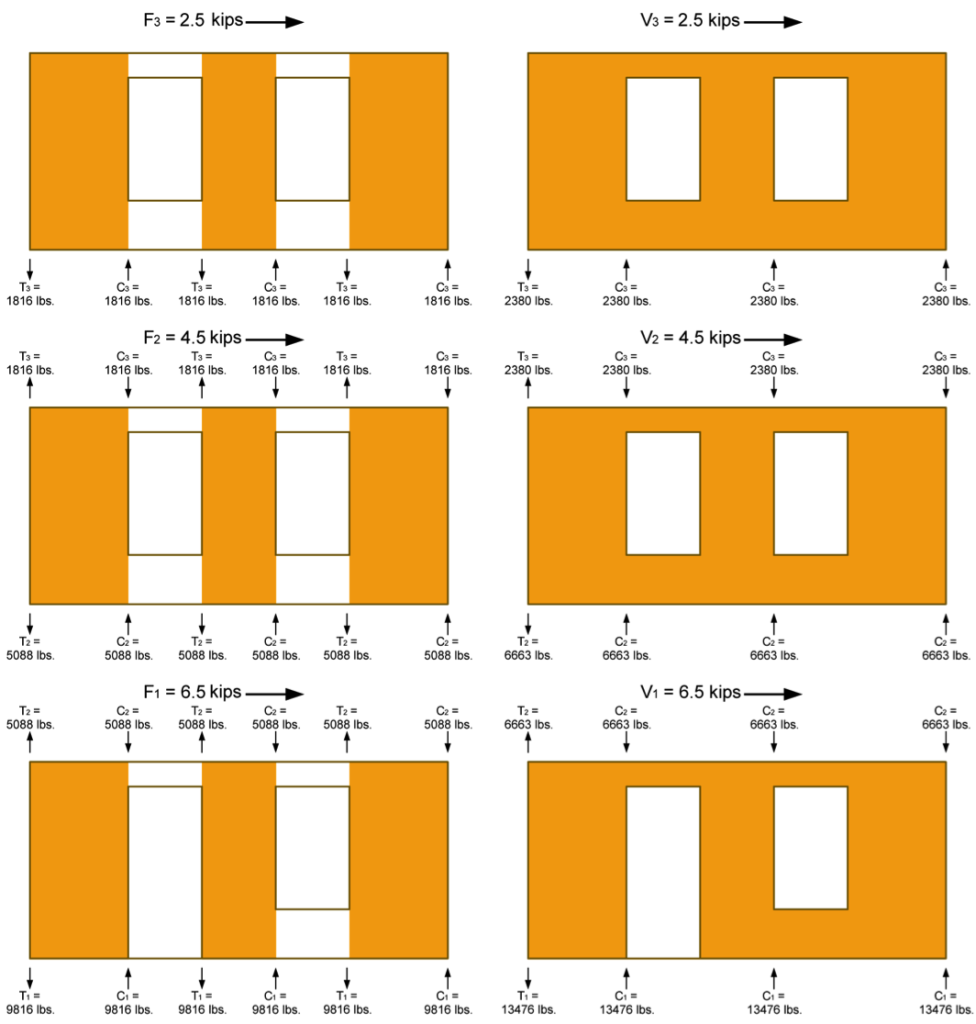
Given:SE blog 1
  • 2021 SDPWS
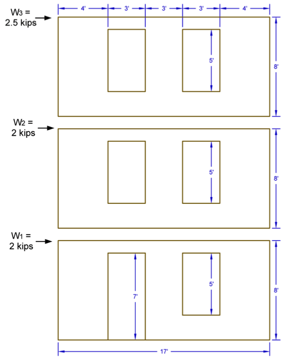
  • 3-Story Wood Framed Shear Wall Line
  • ASD Diaphragm Shear Forces from Wind as Shown
  • Wall and Opening Dimensions as Shown

Solution:

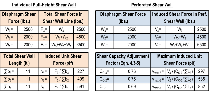
  1. Determine total shear force in each shear wall line.
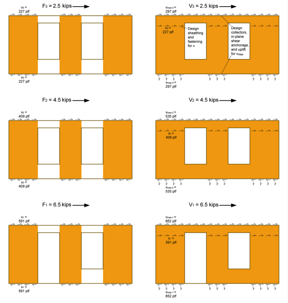
  2. Determine the Induced Unit Shear Force, v, for use with both shear wall types and the Maximum Induced Unit Shear Force, vmax, for the perforated shear wall collectors, shear transfer, and uniform uplift. Note the following:
    1. vmax requires the determination of the Shear Capacity Adjustment Factor, CO, for the perforated shear wall.
    2. The SDPWS provides two methods for determining CO, a tabulated value or a calculated value. This example uses the more precise calculated value.
    3. The perforated method requires the collectors be designed for vmax and the bottom plate to be anchored for a uniform uplift equal to vmax (as illustrated in the following figure).
SE blog 2

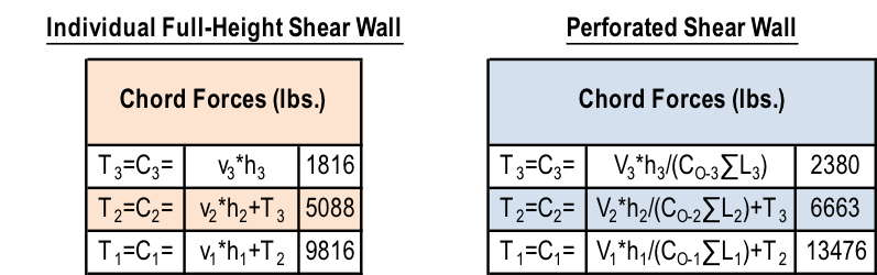
SE blog 43. Determine the Tension, T, and Compression, C, forces in the chords (assume no contribution from dead load for this example). Note the following:

    1. Reverse wind loading will require a mirror image of the T & C forces shown in the following figure.
    2. The tension forces, T, shown in the example reflect the cumulative tension forces as they are transferred down from post-to-post, as is typical with traditional holdowns. For continuous rod systems like ATS, the incremental tension forces (resulting from the unit shear, vor vmax, at that level only) must also be determined as shown in the shear wall specification table at the end of this example.
SE blog 5

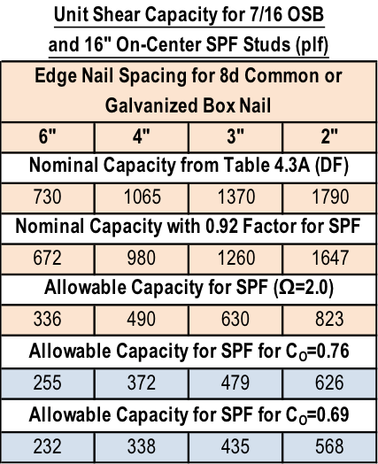
SE blog 5 SE blog 64. Determine sheathing material and fastening pattern based on v calculated in Step 2. The table below is based on 7/16″ wood structural panel sheathing values from SDPWS Table 4.3A. The nominal unit shear values listed in the table shall be adjusted in accordance with SDPWS Section 4.3.3 to determine the allowable unit shear for ASD design.
SE blog 7

A. Individual Full-Height Shear Wall:

i.     v3=227 plf: Use 7/16 OSB with a 6:12 nailing pattern which has an allowable load of 336 plf

ii.     v2=409 plf: Use 7/16 OSB with a 4:12 nailing pattern which has an allowable load of 490 plf

iii.     v1=591 plf: Use 7/16 OSB with a 3:12 nailing pattern which has an allowable load of 630 plf

B. Perforated Shear Wall (apply CO factor to allowable shear capacity):

i.     v3=227 plf: Use 7/16 OSB with a 6:12 nailing pattern which has an allowable load of 255 plf

ii.     v2=409 plf: Use 7/16 OSB with a 3:12 nailing pattern which has an allowable load of 479 plf

iii.     v1=591 plf: Use 7/16 OSB on both sides of the wall with a 4:12 nailing pattern which has an allowable load of 338*2=676 plf

5. Size the posts for compression. Simpson provides some useful tables in the back of the connector catalog with allowable tension and compression loads for a variety of sizes, heights, and species of posts.

6. Select holdowns for the tensions loads and verify post sizes are sufficient. For higher aspect ratio shear walls, the post size and holdown type may significantly reduce the moment arm between center of tension and center of compression, resulting in higher tension and compression forces.

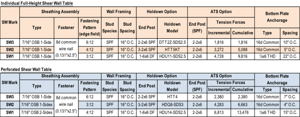
The tables below show the shear wall specification for the walls in the example in a typical format. Note that they do not include some detailing that is required for items such as the uniform uplift force on the bottom plate of all perforated shear walls, or the perforated shear walls with OSB sheathing on both sides.
SE blog 8

There are different ways to address the loads, so let us know if you would do anything differently in your designs.

The Importance of Resilient Communities During Earthquakes

Imagine that it’s 4:30 a.m. and suddenly you’re awakened by strong shaking in your home. Half asleep, you hang on to your bed hoping that the shaking will stop soon. All of a sudden, the floor gives away and you fall. You think, “What just happened? How could this have possibly occurred? Am I alive?”

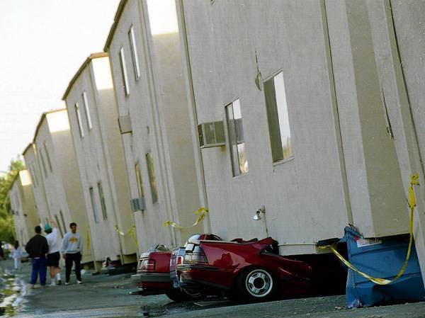
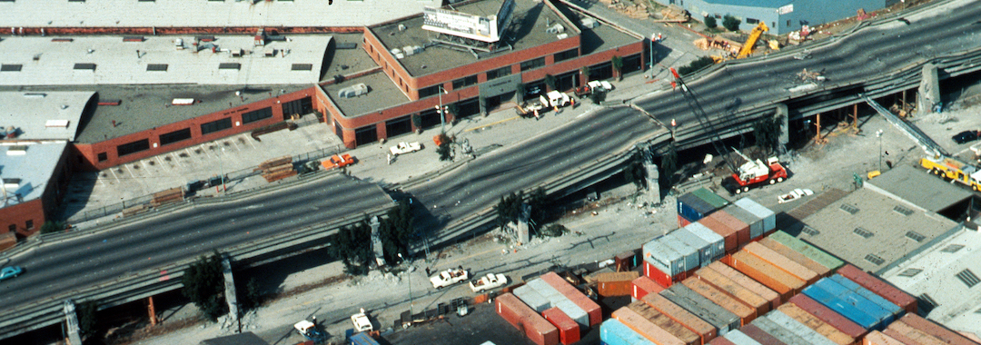
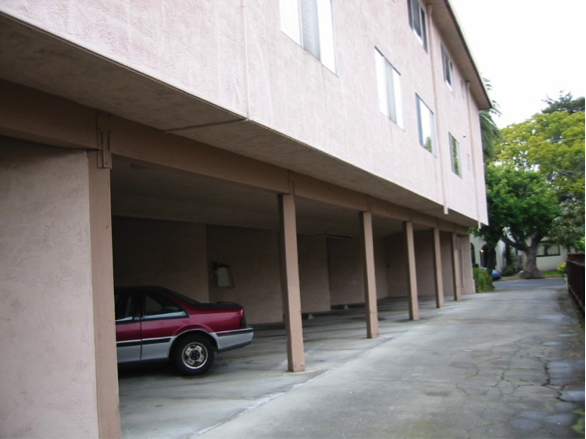
These could have been the thoughts of Southern California residents living in one of the many apartment buildings, which collapsed on January 17, 1994, during a 6.7 magnitude earthquake. The Northridge Earthquake brought awareness to buildings in our communities with a structural weakness known as a soft story, a condition that exists where a lower level of a multi-story structure has 20% or less strength than the floor above it. This condition is prevalent in buildings with tuck-under parking and is found in multistory structures throughout San Francisco, Los Angeles and other cities (see Figure 1). These structures are highly susceptible to major damage or collapse during a large seismic event (see Figure 2).

Soft Story building
Figure 1: Multi-unit wood-frame building with first weak story.
Aftermath of an earthquake
Figure 2: Collapsed soft story tuck under parking building. Image courtesy of LA Times

Soft story retrofits help to strengthen our communities and make them more resilient to major disasters. There are several resources available to structural engineers that need to retrofit weak-story buildings. Some of these resources are mentioned in our September 18 blog post.

During the 2014 SEAOC Convention held in Indian Wells on September 10-13, speakers discussed different methods, analysis and research that address the behavior of various materials and construction types during seismic events along with approaches to retrofit historically poor performing structures. This information can be viewed from the convention’s proceedings available at www.seaoc.org.

On October 20, 2014, the Structural Engineers Association of Southern California (SEAOSC) will be hosting their 4th annual Strengthening Our Cities BAR Summit in downtown Los Angeles. This event brings together many different stakeholders in our built environment, including public officials, building owners and managers, business owners, insurance industry representatives, emergency managers and first responders, and design professionals.

Many prestigious thought leaders, including USGS Seismologist Dr. Lucy Jones will be speaking at the summit, discussing such topics as tools and analysis methods for retrofitting vulnerable buildings and the Building Occupancy Resumption Program (BORP).

Expect a great day full of useful information about ways to strengthen our communities and prepare for major earthquakes as well as opportunities to network with like-minded peers. For additional information and to register, visit www.barsummit.org. We also hope you’ll visit our booth. We look forward to speaking with you there.

Remembering Loma Prieta

We all know that earthquakes physically shape the landscape here in California, but they shape careers as well.  Earthquakes I felt while growing up in California’s southern San Joaquin Valley got me thinking about engineering as a career while in high school. When the Loma Prieta earthquake struck on October 17, 1989, like many of you I was watching the World Series live on television and thus got to see the earthquake live as well. I was in my senior year of college at the time, studying Civil Engineering with a structural emphasis. This earthquake cemented the direction I would take in my career. I wanted to be a structural engineer, and I wanted to design buildings that would not fall down in earthquakes.

Continue Reading

Applying new FEMA P-807 Weak Story Tool to Soft-Story Retrofit

We have written about San Francisco’s Soft-Story Retrofit Ordinance and Soft-Story Retrofits before on the blog. I wanted to discuss in more detail the issues with soft story buildings and FEMA’s new tool for addressing them. Under the San Francisco Ordinance, wood-framed residential structures that have two or more stories over a “soft” or “weak” story require seismic retrofit. So far, more than 6,000 property owners have been notified about complying with the mandate.Continue Reading

Home Seismic Retrofit

The 6.0 magnitude earthquake that struck Napa, CA, in August caused more than 200 injuries and structural damage to many homes and businesses throughout the area. The quake was the largest to hit the San Francisco Bay Area since the Loma Prieta earthquake (6.9 magnitude) in 1989, prompting the governor to declare a state of emergency.

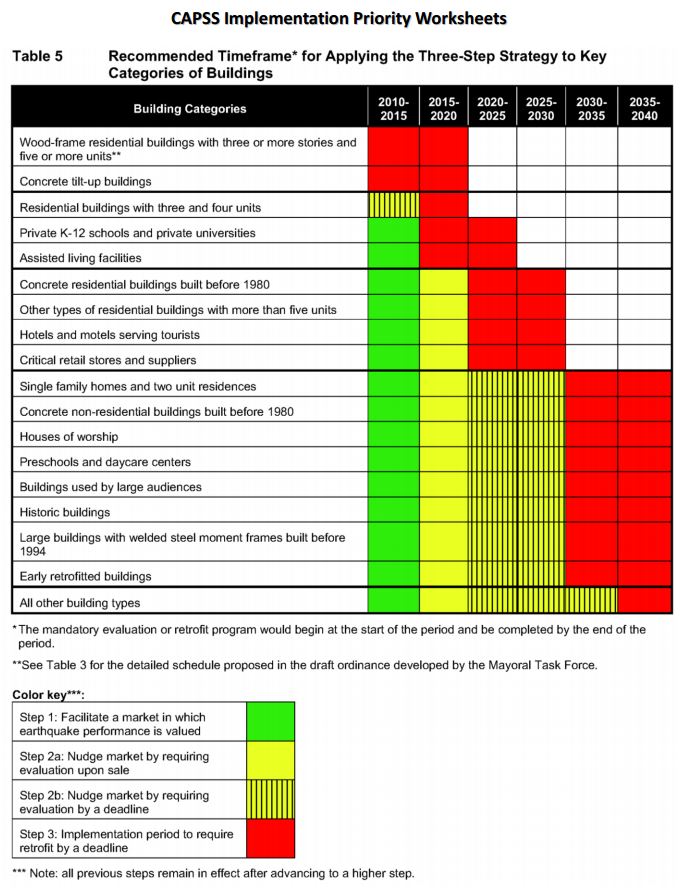
I have done several posts about San Francisco’s Soft-Story Retrofit Ordinance and some of NEES-Soft testing related to soft-story retrofits. The soft-story ordinance only addresses multi-unit residential units and does not require retrofit of single-family homes. Cities are reluctant to mandate seismic evaluation and retrofit of single-family homes for a number of reasons that I won’t discuss here. The draft Earthquake Safety Implementation Program (ESIP) for San Francisco will not recommend mandatory retrofit of single-family homes until 2030.

CAPSS Implementation Priority Worksheet

The good news is homeowners can retrofit their homes without waiting for the government. A couple years ago in this post, I discussed some of the tools available to retrofit existing buildings.

One of these tools is the International Existing Building Code (IEBC), most recently published as the 2021 and 2024 IEBC. The IEBC provides provisions for the repair, alteration, addition, and change of occupancy of existing buildings, as well as requirements for strengthening existing structures. For alterations, these provisions may not require full compliance with current IBC requirements; instead, they are intended to maintain acceptable levels of fire and structural life safety appropriate for existing construction. The IEBC also includes prescriptive seismic strengthening provisions for certain existing buildings, including the retrofit of residential structures with raised or cripple wall foundations to improve earthquake performance.

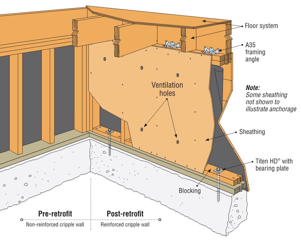
Cripple Wall Reinforcing Schematic

Cripple Wall Retrofit Schematic and Installation

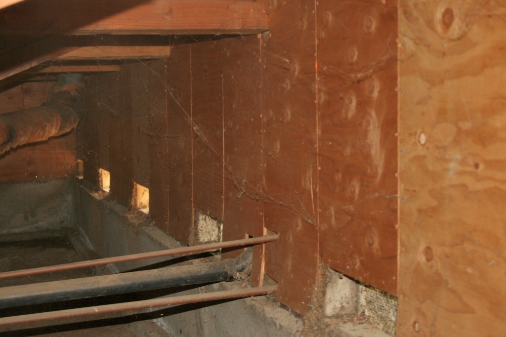
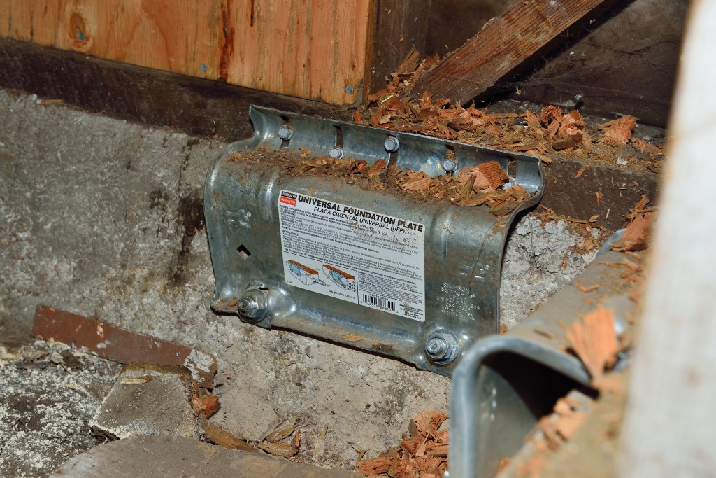
Cripple wall failures are a common type of damage observed in older homes, caused by inadequate shear strength in the cripple wall. An additional failure point is the attachment of the wood sill plate to the foundation. Having a strong connection between the wood structure and the concrete foundation is critical in an earthquake. Since the work required to strengthen these connections is typically performed in a crawlspace or unfinished basement, it is a relatively low-cost upgrade that is extremely beneficial to structural performance.

Retrofit with UFP Foundation Plate in Napa

Our website has information for retrofitting your home. The Seismic Retrofit Guide has information about how earthquakes affect a home and the steps to take to reinforce the structural frame of a house. The Seismic Retrofit Detail Sheet is intended to help building departments, contractors and homeowners with seismic retrofitting. It includes common retrofit solutions for reinforcing cripple walls and foundation connections.

One business owner in Napa chose to retrofit her building when she purchased it. You can see her video narrative here.

Snow Loads vs. Top Chord Live Loads – A Historical Look at Snow Loading for Trusses

In my former life working as a consulting engineer, I reviewed many truss submittal packages. I remember during my reviews wondering how it was possible to get so much information on to an 8½ inch by 11 inch piece of paper. I also remember how a lot of what was being reported was difficult to understand without some help interpreting the information. 

As many of you may know, Simpson Strong-Tie has ventured into the truss industry and we are now offering truss connector plates and software to component manufacturers around the country. So given my past experiences, I figure some of you might appreciate some insight into the engineering that goes on behind those truss submittal packages. So I have asked one of our great truss engineers, Kelly Sias, to put together some blog posts on the topic that we can share our knowledge with you. Kelly has worked in the truss industry for years and spent time as the Technical Director at the Truss Plate Institute. I am sure her blog posts are going to help all of us have a better appreciation for trusses.

Have you ever been involved in a discussion with someone on a project that ended with “but that’s the way we’ve always done it!”? I heard those words spoken by a contractor in my first engineering job when I tried explaining why his single stud would not work at a particular location. When he said something about his grandfather having always done it that way, I knew I could explain the calculations all day and it wouldn’t do much good.Continue Reading

Midrise of Steel

Guest blogger Jeff Ellis, engineering manager

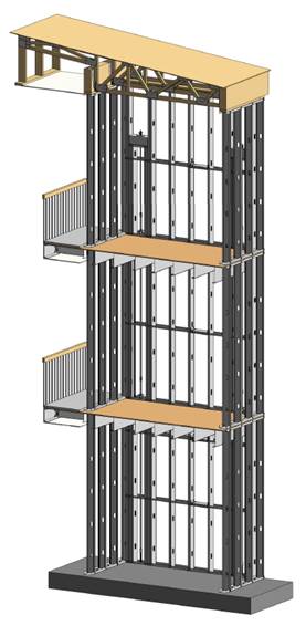
The number of midrise structures constructed using light-frame cold-formed steel (CFS) certainly seems to be increasing each year. As with any material, there are benefits and challenges, especially in areas of moderate to high seismic risk. This post will discuss these as well as potential solutions.

Light-frame CFS midrise construction often uses ledger floor framing primarily to facilitate the load transfer detailing at the floor, tension anchorage (tie-downs or hold-downs) and compression chord studs or posts designed to resist the amplified seismic overturning loads. CFS framing is typically thin and singly symmetric.

Various CFS Construction Floor Framing Methods


Amplified Seismic Load

The AISI Lateral Design standard (AISI S213-07/S1-09) Section C5.1.2 requires that the nominal strength of uplift (tension) anchorage and the compression chord studs for shear walls resist the lesser of (1) the amplified seismic load or (2) the maximum load the system can deliver when the response modification coefficient, R, greater than 3. The amplified seismic load is defined as the load determined using the ASCE 7 seismic load combinations with the overstrength factor, Wo, which may be taken as 2.5 for CFS framed shear wall systems with flexible diaphragms.

Typically, the maximum the system can deliver to the uplift anchorage or chord studs is taken as the forces determined using the nominal shear strength of the shear wall assembly tabulated in the seismic shear wall table in S213 multiplied by 1.3. The S213 commentary accounts for the tabulated loads being based on Sequential Phased Displacement (SPD) rather than CUREE cyclic protocol and the degraded backbone curve. See the Structure magazine article that discusses the design of CFS framed lateral force-resisting systems.

Continuous Rod Tie-Down Systems

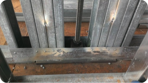
Light-framed CFS over three stories often use continuous rod tie-down systems rather than cold-formed steel hold-downs to resist shear wall overturning forces as they offer increased load capacity. Neglecting the dead load contribution, the amplified seismic load requirement for CFS shear walls using an R greater than 3 results in an 80% increase in the load used to size the continuous rod tie-down system compared to design level loads. For shear walls using an R greater than 3, it is important to note on the design drawings whether the uplift loads shown are ASD, LRFD, amplified ASD or amplified LRFD so the appropriate tie-down system may be designed.

Continuous Rod Tie-Down System Resisting Shear Wall Overturning Forces

Continuous rod tie-down systems are designed not only for strength, but also checked to ensure they do not deflect too much to cause the top of shear wall drift to exceed the code limit or to exceed the 0.20” vertical story deflection limit required by some jurisdictions and ICC-ES AC316. Take-up devices are used in CFS framed structures to take-up construction and settlement gaps that may occur.  AISI S200 Section C3.4.4 states that a gap of up to 1/8” might occur between the end of wall framing and the track. The vertical elongation of the continuous rod tie-down system includes rod elongation (PL/AE) and the take-up device deflection due to the seating increment and the deflection under load.

In addition, coordination is important in using continuous rod tie-down systems in CFS structures because the walls are often prefabricated offsite. An example is the consideration of the appropriate detail for the steel bearing plate installed at the floor sheathing in the story above to resist the uplift (tension) force from the story below.

One possible detail is to install the bearing plate in the bottom CFS track under all the CFS chord studs, but it’s important to ensure the bottom track flanges are deep enough to screw them to the stud flanges as the bearing plate can have a thickness of 1 ½” or more and typical tracks use 1 ¼” flanges. It is also important to ensure that the bearing plate width fits in the track. Another possible detail is to install the bearing plate under the CFS track under all the CFS chord studs.  However, then it must be cut into the floor sheathing and may cause the bottom track to be raised at the bearing plate. For this detail, the floor shear transfer must be detailed through the ledger into the CFS framing.

Continuous Rod Tie-Down System Steel Bearing Plate Coordination Issues

Concrete Tension Anchorage

The concrete tension anchorage is designed according to ACI 318 Appendix D using the continuous steel rod material and size in accordance with S213 to have the nominal strength to resist the lesser of the amplified seismic force or the maximum load the system can deliver. ACI 318-11 Section D.3.3.4.3 offers four force limits for design of concrete tension anchorage design in Seismic Design Category C through F:

(1)   The concrete nominal tension anchorage strength shall be greater than 1.2 times the ductile steel rod nominal tension anchorage strength

(2) The anchorage design strength shall be greater than the maximum tension force that can be delivered by a yielding attachment;

(3) The anchorage design strength shall be greater than the maximum tension force that can be delivered by a non-yielding attachment; and

(4) The anchorage design strength shall be greater than the amplified seismic force.

Typically either option (1) or (4) is used where (1) would lead to less concrete required than (4) if the bolt is efficiently sized while (4) would be required for such conditions as a vertical irregularity.  See the concrete anchorage and podium anchorage SE Blog posts for more details.

ACI 318-11 Section D.3.3.4.3 Anchorage Design Options

CFS Wall Stud Bracing

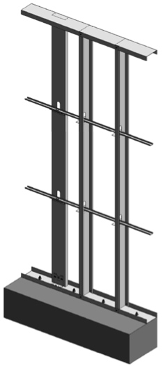
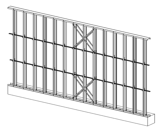
CFS studs are typically thin and singly symmetric and thus require bracing. AISI S211 (Wall Stud Design Standard) permits two types of bracing design that cannot be combined; sheathing based or steel based. There are limits on the stud axial strength when using sheathing braced design. It’s important to identify on the drawings that the sheathing braces the studs and another load combination must be used for the stud design.

2012 IBC Section 2211.4 requires stud bracing to be designed using either AISI S100 (North American Specification) or S211 (Wall Stud Design Standard). S100-07 Section D3.3 required nominal brace strength is to be 1% of the stud’s nominal compressive axial strength, but S100-12 Section D3.3 changes this to the required brace strength is to be 1% of the stud’s required compressive axial strength (demand load). In addition, D3.3 requires a certain stiffness for each brace. AISI S211 required brace strength is to be 2% of each stud’s required compressive axial strength for axially loaded studs and, for combined bending and axial loads, be designed for the combined brace force per S100 Section D3.2.2 and 2% of the stud’s required compressive axial strength.

There are two primary types of steel stud bracing systems: bridging and strap bracing. U-channel bridging extends through the stud punchouts and is attached to the stud with a clip, of which there are various solutions such as this post on Wall Stud Bridging.  Bridging bracing requires coordination with the building elements in the stud bay. It installs on one side of the wall, and does not bump out the wall sheathing. It also requires periodic anchorage to distribute the cumulative bracing loads to the structure for axially loaded studs often using strongback studs and does not require periodic anchorage for laterally loaded studs since the system is in equilibrium as the torsion in the stud is resisted by the U-channel bending.

Flat strap bracing is installed on either side of the wall and at locations other than the stud punchout. It bumps out the sheathing and requires periodic anchorage to distribute the cumulative bracing loads to the structure for axially and laterally loaded studs.

Beam

Strap and Block Bracing
Strap and Block Stud Bracing Anchored Periodically to Structure Using Strongbacks

Beam2

Bridging and Clip Bracing Anchored Periodically to Structure Using Strongbacks
Bridging and Clip Bracing Anchored Periodically to Structure Using Diagonal Strap Bracing

Light-frame cold-formed steel construction has been used successfully for many projects, but there are challenges  that must be addressed to ensure code compliance and desired performance. Some beneficial resources for designing CFS structures are the SEAOC 2012 IBC Structural/Seismic Design Manual Volumes 1 and 2 and the Cold-Formed Steel Engineers Institute’s (CFSEI) website where you can find technical notes and design guides.

What have been some of your observations or challenges in designing cold-formed steel midrise structures?

City of San Francisco Implements Soft-Story Retrofit Ordinance

The city of San Francisco is a unique construction environment that is 98% built-out with little new residential construction. Protecting the existing structures is particularly imperative to save the character of the city and maintain the population base by preventing a major migration out of the city after a large seismic event.

The Community Action Plan for Seismic Safety (CAPSS) was a San Francisco Department of Building Inspection 10-year-long study started in 1998 to study earthquake risks in San Francisco and develop suggestions for mitigating loss of life and property damage from future earthquakes. I once worked as a volunteer on a sidewalk survey to inventory soft-story buildings as part of CAPSS. The key recommendations of CAPSS evolved into the CAPSS Earthquake Safety Implementation Program (ESIP), which has 50 tasks that will be implemented over the next 30 years.

One of those tasks includes the Mandatory Soft-Story Retrofit Program, which Mayor Ed Lee signed into law on April 18, 2013 at the annual commemoration of the 1906 San Francisco Earthquake. The law requires wood-framed buildings that:

  • Were built prior to 1978
  • Are three stories or more and,
  • Have five or more dwelling units

to be evaluated and brought into compliance. The city sent notices to building owners on September 15. It’s estimated that there are between 4,000 and 10,000 structures that fall under the program.

Continue Reading

Are the Load Combinations Balanced?

In April’s post about the Omega Factor, one commenter asked of the 1.2 increase allowed by ASCE 12.4.3.3, “Why do they allow a stress increase for allowable combinations? Seems unconservative for steel now that they have essentially balanced the ASD capacity with LRFD.”

To be honest, I have never spent much time analyzing which design methodology was more or less conservative. If I was designing with wood I would use ASD, and if it was with concrete I would use LRFD. Steel was strictly ASD early on in my design career, but LRFD usage grew. The question about balance made me curious. Are the load combinations balanced?

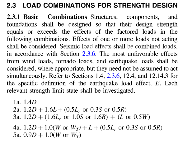
ASCE7-22 Basic ASD Load Combinations
ASCE7-22 LRFD Load Combinations

Of course, just comparing the load combinations would be meaningless. We know the LRFD combinations result in higher design forces. But those higher forces are compared to higher design strengths. So we need to normalize things.

Continue Reading

Open Front Structure Wind Pressure Design

We received a request from Martin H., one of our blog readers, to discuss the method for determining roof wind pressures on an open front agricultural building. The inquiry was regarding clarification on analyzing the roof pressure when a combined external and interior pressure exists and whether these are additive.

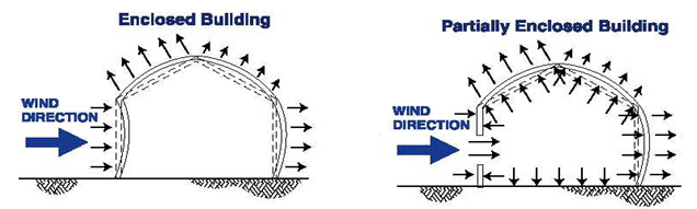
Wind Pressure Figure

As can be seen in the above illustrations, the net design pressure on the roof is the sum of the uplift on the exterior surface and the uplift on the interior surface from any internal pressure. ASCE 7 provides a method for determining this pressure. Specifically, ASCE 7-22 will be used for the remainder of this post. Assuming the three remaining sides of the open front structure are walls without openings, the building will be classified as partially enclosed by the definitions of Section 26.2.

ASCE 7-22 provides for two methods for determining the Main Wind Force Resisting System (MWFRS) wind loads for partially enclosed buildings, the Directional Procedure in Chapter 27, and the Envelope Procedure in Chapter 28.

When using the Directional Procedure, the net wind load is calculated using the following equation:

P = qGCp – qi(GCpi)

When using the Envelope Procedure, the net wind load is calculated using the following equation:

 P = qh[(GCpf) – (GCpi)]  

In each of these equations, the first portion determines the pressure on the exterior surface, and the second portion determines the pressure on the interior surface. So the variable for calculating the internal pressure is the internal pressure coefficient GCpi.

The internal pressure coefficient is provided in Table 26.11-1 based on three different categories of building enclosure.

Enclosure Classification

(GCpi)

Open Buildings

0.00

Partially Enclosed Buildings

+0.55

-0.55

Enclosed Buildings

+0.18

-0.18

Table 26.11-1

In the case of an open front structure, it is assumed that the partially enclosed internal pressure coefficient must be used. This coefficient is 3x greater than when the building envelope is classified as enclosed. Use of this higher coefficient in the design will account for the interior pressure on the underside of the roof combined with the exterior pressure.

MWFRS versus C&C

Another somewhat related question: to what level loads should the roof anchorage forces be calculated, MWFRS or C&C (Component and Cladding)? I have often been asked this question, and wrote a Technical Note published by CFSEI (Cold-Formed Steel Engineers Institute) in July 2009.

What are your thoughts?

– Sam