


While stick-frame roofs are sometimes preferred to premanufactured roof trusses in some areas of the country because they can accommodate larger attics, higher ceilings, and complex roof shapes, the code requirements for these roofs are often more complex. That’s largely because, unlike truss-framed roofs, the code needs to provide a complete prescriptive method of building the roof, including the multitude of connections that must be made in the field. And, to complicate matters further, the code requirements for stick-frame roofing have been rewritten in each of the last two code cycles. I’d like to give you a high-level overview of some of those changes. In a previous SE Blog post, we discussed the design concepts of stick-framed roofs, and summarized a few of the solutions offered by the Simpson Strong-Tie® connector system for stick-frame roofing. The main concept in that post was the necessity of a continuous tie across the bottom of the rafter system to prevent the heels of the rafters from spreading under load and pushing out on the tops of the walls.
Category: Lateral Systems
Little did we know when we introduced our first holdown in 1966 that our product innovations would lead us to solutions that can help hold together five-story buildings during an earthquake or allow builders to more easily retrofit structures and install larger window and door openings in homes. Our offering of lateral-force resisting systems, including Wood and Steel Strong-Wall® shearwalls, Strong Frame® moment frames and new Strong-Rod™ Systems, gives designers and engineers added design flexibility in wood-frame construction and the confidence that almost anything is possible.
Introducing the Code-Listed Strong-Wall® Site-Built Portal Frame System for Prescriptive Design
Many of you reading this may already be familiar with our Strong-Wall site-built portal frame system, or PFS for short. Simpson Strong-Tie launched the PFS last spring to provide designers, builders and contractors in prescriptive markets with a simple and cost-effective solution to meet code-prescribed wall bracing requirements for narrow wall widths.

Designing Resilience: NEESWood Capstone a Decade Later
In 2009, Simpson Strong-Tie participated in an unprecedented research event to highlight the importance of earthquake-resistant wood construction.
The event, the world’s largest earthquake test, was a collaborative Network for Earthquake Engineering Simulation project. It teamed academics, engineers, and industry researchers from around the world to subject a structure to what engineers refer to as the “maximum considered event” (MCE), a large, rare earthquake projected to occur, on average, approximately every 2500 years.
Continue Reading

Questions Answered: Strong-Wall® Site-Built Portal Frame System
In this post, we follow up on our April 17 webinar, Meeting Braced-Wall Requirements: A New Portal Frame Solution, by answering some of the interesting questions raised by attendees.
During the webinar, we discussed how the Strong-Wall Site-Built Portal Frame System (PFS) provides designers, builders and contractors in prescriptive jurisdictions with a new alternative to IRC wall-bracing methods. In case you weren’t able to join our discussion, you can watch the on-demand webinar and earn PDHs and CEUs here.
Continue Reading

Roof Framing: Building Strong Stick-Frame Roofs
Although truss-designed roofs are predominant throughout most of the residential construction industry, there are regions where building with stick-frame roofs is still common. In this post, Randy Shackelford discusses some design choices available to stick-frame builders, the challenges they pose, and the solutions offered by the Simpson Strong-Tie® connector system for stick-frame roofing. The post will also discuss some changes in the 2021 IRC that affect construction of stick-frame roofs.

FAQs Regarding Strong-Rod Anchor Tiedown Systems (ATS) for Shearwall Overturning
How would a six-story light-frame wood building perform in a large earthquake? Back in 2009, Simpson Strong-Tie was a partner in the World’s Largest Earthquake Test, a collaboration of the NEESWood project, to answer that question. This was a full-scale test which subjected the building to 180% of the Northridge earthquake ground motions (approximately a M7.5). Within the building, Simpson Strong-Tie connectors and Strong-Frame SMF were used, with the Strong-Rod™ anchor tiedown system (ATS) serving as holdown for each shearwall.
The NEESWood building was designed under Performance-Based Design methodology, and the test was conducted as validation for the approach. Buildings of similar size to the NEESWood building are built to current codes using similar products. Mid-rise light-frame wood structures continue to be a popular form of construction in various densely populated cities across the country. As part of the lateral-force-resisting system, continuous rod systems are used as the holdown for the shearwall overturning restraints. Simpson Strong-Tie has been involved with continuous rod systems since the early 2000s when we launched the Strong-Rod anchor tiedown system.
Today, rod manufacturers design the continuous rod systems with design requirements (loading, geometry, etc.) Supporting documents (e.g., installation details, layouts, RFI/markups and calculations) are submitted for each unique project. Over the years, engineers have asked many questions related to the design of these systems. In this week’s blog, we will explore Frequently Asked Questions pertaining to Strong-Rod ATS systems used as shearwall overturning restraints (holdowns).
Is there a code report for the system?
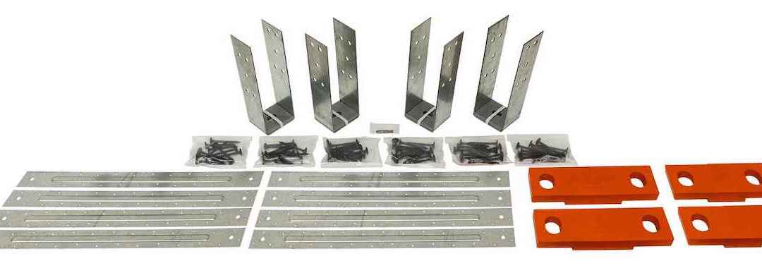
The Strong-Rod ATS system is a series of rods (fully threaded rods and proprietary Strong-Rods), coupler nuts, bearing plates, nuts and shrinkage compensation devices (ATUD/TUD and RTUD).
The majority of these components are designed in accordance with the building code and reference standards (e.g., NDS, AISC). A project-specific calculation package is submitted for each job that addresses the evaluation of these elements. Therefore, these elements are not listed in evaluation reports.
Shrinkage compensation devices, on the other hand, are proprietary components which are not addressed by the building code or reference standards. Therefore, they are tested in accordance with ICC-ES acceptance criteria AC316 and are listed in ICC-ES ESR-2320.
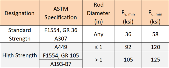
What is the material specification of the rods used above concrete?
The specified rod materials are shown in Table 1.
Can threaded rods or couplers be welded to steel beams?
Simpson Strong-Tie generally does not recommend this practice. Of the materials listed in Table 1, ASTM A307 material is the only specification that contains supplementary requirements for welding. When standard strength rod is supplied to the job, it is not guaranteed that this will be the material provided.
ASTM A449 and A193-B7 high-strength rods develop strength and ductility characteristics through controlled quenching and tempering treatments. Quenching is the rapid cooling of metal (usually by water or oil) to increase toughness and strength. This process often increases brittleness. Tempering is a controlled reheating of the metal which increases ductility after the quenching process. Precise timing in the application of temperature during the tempering process is critical to achieving a material with well-balanced mechanical properties. It is unlikely that field welding will satisfy the requirements of quenching and tempering.
Coupler nuts are generally fabricated from material exhibiting characteristics similar to high-strength rods. Thus, it is not recommended to weld coupler nuts to steel beams due to the potential for embrittlement.
Simpson Strong-Tie specifies a weldable cage which is fabricated from ASTM A36 material for such applications.
How do you calculate the Maximum ASD Tension Capacity provided in the job summary?
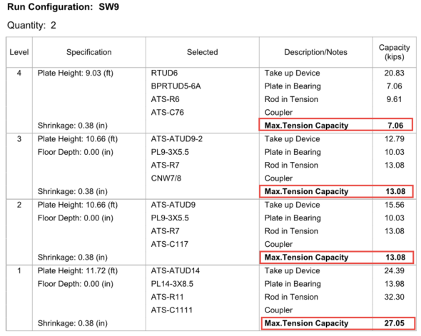
Simpson Strong-Tie provides a comprehensive design package for continuous rod systems used as holdowns for multi-story stacked shearwalls. The individual run calculations, as shown in Figure 1, provide the Maximum Tension Capacity, which correlates to the maximum force the system can deliver. Plan check often requests justification on how these values are derived at each level. These values are calculated, and the process explained below may be used on any Simpson Strong-Tie ATS Job Summary as justification.
The maximum tension capacity published within the Job Summary and the Installation Details is derived using the following procedure:
- Step 1: Evaluate the top-most level. Compare the published capacities of the rod in tension, plate in bearing and the take-up device. The lowest of these three will govern and becomes the Maximum Tension Capacity for this level.
- Step 2: Evaluate the next level down. (a) Sum the Maximum Tension Capacity from Step 1 and the published capacity of the take-up device from this level. (b) Sum the Maximum Tension Capacity from Step 1 and the published capacity of the plate in bearing from this level. (c) Compare derived values from (a) and (b) to the published capacity of rod in tension. The lowest of these three values will govern and becomes the Maximum Tension Capacity of this level.
- Step 3: Repeat Step 2 as necessary until the bottom-most level is reached.
Applying this procedure to the sample run, SW9, will wield the following result:
- Step 1: Evaluate capacities published at Level 4
- Plate in bearing (PBRTUD5-6A) = 7.06 kips governs
- Take-up device (RTUD6) = 20.83 kips
- Rod in tension (ATS-R6) = 9.61 kips
- The lowest value in Step 1 is the plate in bearing, hence 7.06 kips is the maximum load that can be delivered at Level 4 and is the Maximum Tension Capacity.
- Step 2: Evaluate capacities at Level 3
- Maximum Tension Capacity from Level 4 = 7.06 kips (See Step 1)
- Maximum Tension Capacity from Level 4 + take-up device (ATS-ATUD9-2) = 7.06 + 12.79 = 19.85 kips
- Maximum Tension Capacity from Level 4 + plate in bearing (PL9-3×5.5) = 7.06 + 10.03 = 17.09 kips
- Rod in tension (ATS-R7) = 13.08 kips governs
- The lowest value in Step 2 is the rod in tension, hence 13.08 kips is the maximum load that can be delivered at Level 3 and is the Maximum Tension Capacity.
- Step 3: Evaluate capacities at Level 2
- Maximum Tension Capacity from Level 3 = 13.08 kips (See Step 2)
- Maximum Tension Capacity from Level 3 + take-up device (ATS-ATUD9-2) = 13.08 + 15.56 = 28.64 kips
- Maximum Tension Capacity from Level 3 + plate in bearing (PL9-3×5.5) = 13.08 + 10.03 = 23.11 kips
- Rod in tension (ATS-R7) = 13.08 kips governs
- The lowest value in Step 3 is the rod in tension, hence 13.08 kips is the maximum load that can be delivered at Level 2 and is the Maximum Tension Capacity.
- Step 4: Evaluate capacities at Level 1
- Maximum Tension Capacity from Level 2 = 13.08 kips (See Step 3)
- Maximum Tension Capacity from Level 2 + take-up device (ATS-ATUD14) = 13.08 + 24.39 = 37.47 kips
- Maximum Tension Capacity from Level 2 + plate in bearing (PL14-3×8.5) = 13.08 + 13.98 = 27.05 kips governs
- Rod in tension (ATS-R11) = 32.30 kips
- The lowest value in Step 4 is due to the plate in bearing, hence 27.05 kips is the maximum load that can be delivered at Level 1 and is the Maximum Tension Capacity.
In the System Deflection Summary page(s) of the Job Summary, is the Total System Deflection provided at Allowable or Strength levels?
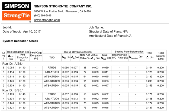
Immediately following the individual run calculations in each job summary, Simpson Strong-Tie provides a summary of deflection of the rod system similar to what is shown in Figure 2. This breaks down the deformation of all components being considered. In the example below, the rod elongation and deflection of the take-up device are summed to provide the total deflection.
The calculated system deflection is presented at ASD level. See section below for how to use these system deflections for your drift calculation.
What system deflection limit do you typically design to, and what does that include?
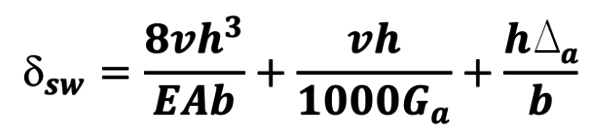
Unless otherwise specified on the plans or required by the building jurisdiction, Simpson Strong-Tie will design the continuous rod system to satisfy the deformation limits set forth in ICC-ES Acceptance Criteria (AC316). In some instances, the Designer may need a more restrictive deformation due to project specific conditions (e.g., tight building separations) and will require rod manufacturers to design for a lower deformation. Some jurisdictions (e.g., City of San Diego, City of San Francisco) may also have specific design requirements that continuous rod systems must conform to. The minimum recommended per-floor deformation limit set forth in AC316 is:
(Rod Elongation) + (Shrinkage Compensation Device Deflection) ≤ 0.2” (ASD),
Or (PDL/AE) + [ΔR + ΔA(PD/PA)] ≤ 0.2” (ASD)
Where:
PD = ASD demand cumulative tension load (kips)
L = length of the rod between restraints – i.e., floor-to-floor (in.)
A = net tensile area of the rod (in.2)
E = Young’s Modulus of Elasticity (29,000 ksi)
ΔR = seating increment of the shrinkage compensation device (as published in ICC-ES evaluation report)
ΔA = deflection of the shrinkage compensation device at the allowable load (as published in ICC-ES evaluation report)
PA = Allowable capacity (kips)
Should deformation limits be specified in the construction documents?
Simpson Strong-Tie strongly recommends this information be included in the construction documents. Along with the cumulative tension and compression forces, the required deformation limits for the holdown are important to ensure that rod manufacturers are designing the holdown to satisfy the desired shearwall performance.
How do I use the system deformation limit?
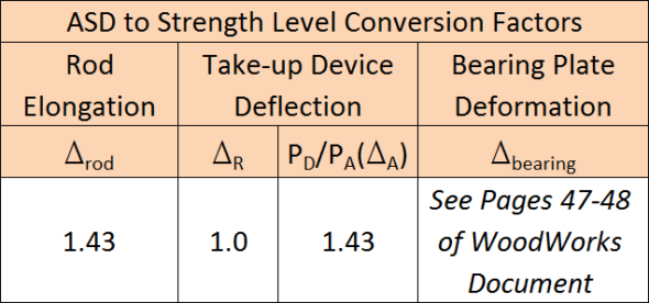
The System Deflection is the total deformation of the holdown system from floor to floor (refer to the last two columns in Figure 2). This information represents the total ASD holdown deformation term, Δa, for each level and is to be used in the shearwall drift equation from the Special Design Provisions for Wind and Seismic (2015 SDPWS 4.3-1).
ASCE 12.8.6 requires that shearwall drift be calculated at strength level. Therefore, the information provided within the System Deflection Summary page needs to be converted from ASD to Strength Level. The conversion factors in Table 2 can be used to convert the ASD deformations to strength level. For discussions and methodology in converting bearing plate deformation to strength level, please refer to the WoodWorks Design Example of a Five-Story Wood Frame Structure over Podium Slab found here.
Can rod systems be used in Type III construction?
Yes! 2015 IBC §2303.2.5 requires that Fire Retardant-Treated Wood (FRTW) design values be adjusted based on the type of treatment used on the project. Adjustment factors vary for each FRTW manufacturer; refer to the ICC-ES evaluation report of the specified FRTW manufacturer for the unique adjustment values. Rod manufacturers need to know what treatment is being used so this information can be taken into consideration when designing compression posts and incremental bearing (bearing plates).
For more information and previous discussions on fire protection in mid-rise construction, see our previous posts: Fire Protection Considerations with Five-Story Wood-Frame Buildings Part 1 and Part 2, and Connectors and Fasteners in Fire-Retardant-Treated Wood.
What are Simpson Strong-Tie’s guidelines for fire caulking material?
While there are many options for fire-rated caulking, these products can be used in conjunction with the Simpson Strong-Tie ATS system. Below is a list of considerations when selecting and specifying a material for use where the rods penetrate the top and sole plates:
- The fire-rated caulking shall not be corrosive to metal when used in contact with ATS components.
- Direct contact with shrinkage compensating devices (e.g., TUD, ATUD, RTUD) shall be avoided. Shrinkage compensating devices have moving components and may not function properly with debris interference.
- Indirect contact with shrinkage compensating devices shall also be avoided. Shrinkage compensation accumulates up the building and therefore the largest shrinkage occurs at the top of the building. As such, when the building shrinks, remnants of the material may still be stuck to the threads of the rod and may be detrimental to the performance of some shrinkage compensating devices (e.g., an RTUD). It is recommended to detail the installation with shrinkage taken into consideration.
- The fire-rated caulking should be pliable to accommodate wood shrinkage and the building moving down during this process.
- The performance and the suitability of fire-rated caulking are outside the scope of Simpson Strong-Tie.
Why doesn’t your design include compression post design?
If the Engineer of Record has already specified compression posts to be used with a continuous rod system, Simpson Strong-Tie will not provide these on the holdown installation drawings. This is primarily done to prevent discrepancies between the specification in the contract documents and what is shown on the installation drawings.
What is the maximum spacing between compression posts?
For platform-framed structures, the maximum spacing between compression posts is 9″. The large majority of Simpson Strong-Tie bearing plates will fit within the 9″ spacing requirement, eliminating the need for notching compression posts. In some framing conditions, such as balloon framing or a top chord bearing truss, the maximum spacing will be reduced to 6″. This is due to the limited amount of space between the top of the compression posts transferring uplift (via bearing) into the point of restraint (e.g., bearing plate) at the level above. To ensure this load path is complete, the posts need to be spaced closer.
What is the nailing schedule for the bridge block to the king studs?
Simpson Strong-Tie doesn’t recommend nailing the bridge block to the cripple as the bridge block member will shrink. Locking the bridge block in place may result in a gap forming between the bottom of the bridge block member and the top of the cripple studs, which is not accounted for in the Total System Deflection.
Are there any published documents with design examples of continuous rod systems used in mid-rise construction?
There are two resources publicly available that provide discussion and examples. The first is a manual published by the Structural Engineers Association of California (SEAOC). Titled 2015 IBC SEAOC Structural/Seismic Design Manual Volume 2 – Examples for Light-Frame, Tilt-Up and Masonry Buildings, this document provides two examples – one for a four-story wood hotel building, and the other for a three-story cold-formed steel apartment building on concrete podium deck.
Another useful resource is published by WoodWorks and is a design example of a five-story wood-frame structure over podium slab. This document can be found here.
What questions do you have about the Strong-Rod ATS System? Leave them below.
5 Steps to a Successful Soft-Story Retrofit
Last year, I gave a presentation at the annual National Council of Structural Engineers Associations (NCSEA) Summit in Orlando, Florida, titled “Becoming a Trusted Advisor: Communication and Selling Skills for Structural Engineers.” As this was a summit for the leaders of the structural engineers associations from across the country, I wasn’t sure how many people would find it valuable to spend their time learning about a very nontechnical topic. To my surprise and delight, the seminar ended up being standing-room only, and I was able to field some great questions from the audience about how they could improve their selling and communication skills. In the many conversations I had with the conference attendees after my presentation, the common theme was that engineers felt they needed more soft-skills training in order to better serve their clients. The problem, however, was finding the time to do so when faced with the daily grind of design work.
When I started my first job as a design engineer at a structural engineering consulting firm straight out of school, I was very focused on improving and expanding my technical expertise. Whenever possible, I would attend building-code seminars, design reviews and new product solution presentations, all in an effort to learn more about structural engineering. What I found as I progressed through my career, however, was that no matter how much I learned or how hardworking I was, it didn’t really matter if I couldn’t successfully convey my knowledge or ideas to the person who really mattered most: the client.

How can an engineer be most effective in explaining a proposed action or solution to a client? You have to be able to effectively sell your idea by understanding the needs of your client as well as any reasons for hesitation. The importance of effective communication and persuasion is probably intuitive to anyone who’s been on the sales side of the business, but not something that occurs naturally to data-driven folks like engineers. As a result of recent legislation in California, however, structural engineers are starting to be inundated with questions from a group of folks who have suddenly found themselves responsible for seismically upgrading their properties: apartment building owners in San Francisco and Los Angeles.
Imagine for a moment that you are a building owner who has received a soft-story retrofit notice under the City of Los Angeles’ Ordinance 183893; you have zero knowledge of structural engineering or what this term “soft-story” even means. Who will be your trusted advisor to help you sort it out? The City of Los Angeles Department of Building and Safety (LADBS) has put together a helpful mandatory ordinance website that explains the programs and also offers an FAQ for building owners that lets them know the first step in the process: hire an engineer or architect licensed in the state of California to evaluate the building.

I’ve had the opportunity to be the first point of contact for a building owner after they received a mandatory notice, because it turns out some relatives own an apartment building with soft-story tuck-under parking. Panicked by the notice, they called me looking to understand why they were being forced to retrofit a building that “never had any problems in the past.” They were worried they would lose rent money due to tenants needing to relocate, worried about how to meet the requirements of the ordinance and, most importantly, worried about how much it was going to cost them. What they really wanted was a simple, straightforward answer to their questions, and I did my best to explain the necessity behind retrofitting these vulnerable buildings and give an estimated time frame and cost that I had learned from attending the first Los Angeles Retrofit Resource Fair in April 2016. With close to 18,000 buildings in the cities of San Francisco and Los Angeles alone that have been classified as “soft-story,” this equates to quite a number of building owners who will have similar questions and be searching for answers.
To help provide an additional resource, Simpson Strong-Tie will be hosting a webinar for building owners in the Los Angeles area who have received a mandatory soft-story retrofit notice. Jeff Ellis and I will be covering “5 Steps to a Successful Retrofit” and helping to set a clear project path for building owners. The five steps that Simpson Strong-Tie will be recommending are:
- Understanding the Seismic Retrofit Mandate
- Partnering with Design Professionals
- Submitting Building Plans with the Right Retrofit Product Solutions
- Communicating with Your Building Tenants
- Completing Your Soft-Story Retrofit
We encourage you to invite any clients or potential clients to attend this informative webinar, which will lay the foundation for great communication between the two of you. As part of the webinar, we will be asking the building owners for their comments, questions and feedback so we can better understand what information they need to make informed decisions, and we will be sure to share these with the structural engineering community in a future post. By working together to support better communication and understanding among all stakeholders in retrofit projects, we will be well on our way to creating stronger and more resilient communities!
For additional information or articles of interest, there are several resources available:
- Register for the “5 Steps to a Successful Retrofit” webinar on April 26
- Register to attend the 2nd Los Angeles Seismic Retrofit Resource Fair on April 17 (and stop by the Simpson Strong-Tie booth!)
- Find a structural engineer through the Structural Engineers Association of Southern California (SEAOSC)
- Resilience by Design: City of Los Angeles Lays Out A Seismic Safety Plan
- City of San Francisco Implements Soft-Story Retrofit Ordinance
- Soft-Story Retrofits Using the New Simpson Strong-Tie Retrofit Design Guide
- Visit the Simpson Strong-TieSoft-Story Retrofit Center
- The Los Angeles Times Soft-Story Map

SEAOSC Safer Cities Survey Results: How Are We Building Strength and Transparency in Our Communities?
Back in January, employees at Simpson were given the opportunity to learn more about the 401K retirement and investment plan. The big takeaways from my training session were a) save as much as you can as early as you can in life and b) use asset allocation to diversify your portfolio and avoid too much risk. Now, I’m not a big risk taker in general, so I dutifully picked a good blend of stocks and bonds with a range of low to high risk. It seems like a pretty sound strategy and it made me think of all the other ways I tend to minimize risk in my life. When I head to a restaurant, for example, I almost instinctively look for the county health grade sign in the window. When my husband and I went to go buy a new family car a couple years ago, I remember searching the National Highway Traffic Safety Administration (NHTSA) website for crash test ratings. Even when I’m doing something as mundane as having a snack, I will invariably flip over the Twinkie package to see just how many grams of fat are lurking inside (almost 5 per serving!). For all the rankings and information available to the general public for restaurants, cars and snacks, there isn’t much, if any, information to help us know if we’re minimizing our risk for one of the most common activities we do almost every day: walking into a building.

Now before you accuse me of being overly dramatic about such a trivial activity, here’s some food for thought: research has shown that Americans spend approximately 90% of their day inside a building. That’s over 21 hours a day! Have you ever once thought to yourself, “I wonder if this building is safe? Would this building be able to withstand an earthquake or high wind event?” Or how about even taking a step back and asking, “Are there any buildings that are already known to be potentially vulnerable or unsafe, and has my city done anything to identify them?” Unfortunately, that kind of information about a city’s building stock is not usually readily available, but some in the community, including structural engineers, are working to change that.

The charge is being led in California, a.k.a. Earthquake Country, where structural engineers are teaming up with cities to help identify buildings with known seismic vulnerabilities and provide input on seismic retrofit ordinances. Structural engineers have learned quite a bit about how buildings behave through observing building performance after major earthquakes, and building codes have been revised to address issues accordingly. However, according to the US Green Building Council, “…the annual replacement rate of buildings (the percent of the total building stock newly constructed or majorly renovated each year) has historically been about 2%, and during the economic recession and subsequent years, it’s been much lower.” This means that there are a lot of older buildings out there that have not been built to current building codes and were not designed with modern engineering knowledge.
Several cities in California have enacted mandatory seismic retrofit ordinances that require the strengthening of some types of known vulnerable buildings, but no state or nation-wide program currently exists. The Structural Engineers Association of Southern California (SEAOSC) recently decided to launch a study of which jurisdictions in the southern California region have started to take the steps necessary to enact critical building ordinances. According to SEAOSC President Jeff Ellis, S.E., “In order to develop an effective strategy to improve the safety and resilience of our communities, it is critical to benchmark building performance policies currently in place. For southern California, this benchmarking includes recognizing which building types are most vulnerable to collapse in earthquakes, and understanding whether or not there are programs in place to decrease risk and improve recovery time.” These results were presented in SEAOSC’s Safer Cities Survey, in partnership with the Dr. Lucy Jones Center for Science and Society and sponsored by Simpson Strong-Tie.

This groundbreaking report is the first comprehensive look at what critical policies have been implemented in the region of the United States with the highest risk of earthquake damage. According to the Los Angeles Times, the survey “found that most local governments in the region have done nothing to mandate retrofits of important building types known to be at risk, such as concrete and wooden apartment buildings.”
The Safer Cities Survey highlights how the high population density of the SoCal region coupled with the numerous earthquake faults and aging buildings is an issue that needs to be addressed by all jurisdictions as soon as possible. An excerpt from the survey covers in detail why this issue is so important:
No building code is retroactive; a building is as strong as the building code that was in place when the building was built. When an earthquake in one location exposes a weakness in a type of building, the code is changed to prevent further construction of buildings with that weakness, but it does not make those buildings in other locations disappear. For example, in Los Angeles, the strongest earthquake shaking has only been experienced in the northern parts of the San Fernando Valley in 1971 and 1994 (Jones, 2015). In San Bernardino, a city near the intersection of the two most active faults in southern California where some of the strongest shaking is expected, the last time strong shaking was experienced was in 1899. Most buildings in southern California have only experienced relatively low levels of shaking and many hidden (and not so hidden) vulnerabilities await discovery in the next earthquake.
The prevalence of the older, seismically vulnerable buildings varies across southern California. Some new communities, incorporated in the last twenty years, may have no vulnerable buildings at all. Much of Los Angeles County and the central areas of the other counties may have very old buildings in their original downtown that could be very dangerous in an earthquake, surrounded by other seismically vulnerable buildings constructed in the building booms of the 1950s and 1960s. Building codes do have provisions to require upgrading of the building structure when a building undergoes a significant alteration or when the use of it changes significantly (e.g., a warehouse gets converted to office or living space). Seismic upgrades can require changes to the fundamental structure of the building. Significantly for a city, many buildings never undergo a change that would trigger an upgrade. Consequently, known vulnerable buildings exist in many cities, waiting to kill or injure citizens, pose risks to neighboring buildings, and increase recovery time when a nearby earthquake strikes.
The survey also serves as a valuable reference in being able to identify and understand what the known vulnerable buildings types are:
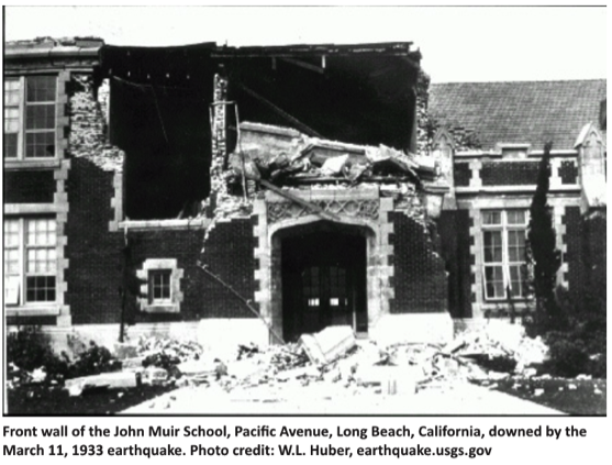
- Unreinforced masonry buildings: brick or masonry block buildings with no internal steel reinforcement — susceptible to collapse
- Wood-frame buildings with raised foundations: single-family homes not properly anchored to the foundation and/or built with a crawl space under the first floor — possible collapse of crawl space cripple walls or sliding off foundation
- Tilt-up concrete buildings: concrete walls connected to a wood roof — possible roof-to-wall connection failures leading to roof collapse
- Non-ductile reinforced concrete buildings: concrete buildings with insufficient steel reinforcement — susceptible to cracking and damage
- Soft first-story buildings: buildings with large openings in the first floor walls, typically for a garage — susceptible to collapse of the first story
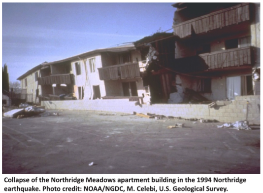
- Pre-1994 steel moment frame buildings: steel frame buildings built before the 1994 Northridge earthquake with connections — susceptible to cracking leading to potential collapse
Along with the comprehensive list of potentially dangerous buildings, the survey also offers key recommendations on how cities can directly address these hazards and reduce potential risks due to earthquakes. As a good starting point, the survey recommends having “…an active or planned program to assess the building inventory to gauge the number and locations of potentially vulnerable buildings…is one of the first steps in developing appropriate and prioritized risk mitigation and resilience strategies.”
Economic costs can be substantial for businesses whose buildings have been affected by an earthquake. After a major seismic event, a structure needs to be cleared by the building department as safe before it can be reoccupied, and it will generally receive a green (safe), yellow (moderately damaged) or red (dangerous) tag. A typical yellow-tagged building could take up to two months to be inspected, repaired and then cleared, meaning an enormous absence of income for businesses. The survey offers a strategy for getting businesses up and running quickly after an earthquake, in order to minimize such losses. The Safer Cities Survey recommends that cities adopt a “Back-to-Business” or “Building Re-Occupancy” program, which would “create partnerships between private parties and the City to allow rapid review of buildings in concert with City safety assessments…Back-to-Business programs…[allow] private parties to activate pre-qualified assessment teams, who became familiar with specific buildings to shorten evaluation time [and] support city inspections.”
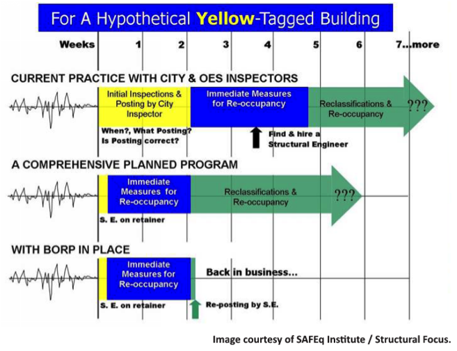
Basically, a program like this would allow a property owner to work with a structural engineer before an earthquake occurs. This way, the engineer is familiar with the building’s layout and potential risks, and can plan for addressing any potential damage. Having a program like this in place can dramatically shorten the recovery time for a business, from two months down to perhaps two weeks. Several cities have already adopted these types of programs, including San Francisco and Glendale, and it showed up as a component of Los Angeles’ Resilience by Design report.
Ultimately, the survey found that only a handful of cities have adopted any retrofit ordinance, but many cities indicated they were interested in learning more about how they could get started on the process. As a result, SEAOSC has launched a Safer Cities Advisory Program, which offers expert technical advice for any city looking to enact building retrofit ordinances and programs. This collaboration will hopefully help increase the momentum of strengthening southern California so that it can rebound more quickly from the next “Big One.”
We all want to minimize the risk in our lives, so let’s support our local structural engineering associations and building departments in exploring and enacting seismic building ordinances that benefit the entire community.
For additional information or articles of interest, please visit:
- Resilience by Design: City of Los Angeles Lays Out a Seismic Safety Plan
- City of San Francisco Implements Soft-Story Retrofit Ordinance
- Seismic Retrofit of Unreinforced Masonry (URM) Buildings
- What Factors Contribute To A “Resilient” Community?
- Soft-Story Retrofits Using the New Simpson Strong-Tie Retrofit Design Guide
- Visit the Simpson Strong-Tie Soft Story Retrofit Center
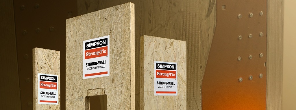
Simpson Strong-Tie® Strong-Wall® Wood Shearwall – Our Old Story of Prefabricated Shearwall Panel Line Part 2
See our latest Prefabricated Shearwall Panel Line – Strong-wall High-Strength Wood Strong-wall at this link: https://seblog.strongtie.com/2021/03/introducing-the-stronger-simpler-and-more-versatile-strong-wall-high-strength-wood-shearwall/
In last week’s blog post, we introduced the Simpson Strong-Tie® Strong-Wall® Wood Shearwall. Let’s now take a step back and understand how we evaluate a prefabricated shear panel to begin with.
First, we start with the International Building Code (IBC) or applicable state or regional building code. We would be directed to ASCE7 to determine wind and seismic design requirements as applicable. In particular, this would entail determination of the seismic design coefficients, including the response modification factor, R, overstrength factor, Ωo, and deflection amplification factor, Cd, for the applicable seismic-force-resisting system. Then back to the IBC for the applicable building material: Chapter 23 covers Wood. Here, we would be referred to AWC’s Special Design Provisions for Wind and Seismic (SDPWS) if we’re designing a lateral-force-resisting system to resist wind and seismic forces using traditional site-built methods.Continue Reading

Simpson Strong-Tie® Strong-Wall® Wood Shearwall – Our Old Story of Prefabricated Shearwall Panel Line Part 1
See our latest Prefabricated Shearwall Panel Line – Strong-wall High-Strength Wood Strong-wall at this link: https://seblog.strongtie.com/2021/03/introducing-the-stronger-simpler-and-more-versatile-strong-wall-high-strength-wood-shearwall/
Some contractors and framers have large hands, which can pose a challenge for them when they’re trying to install the holdown nuts used to attach our Strong-Wall® SB (SWSB) Shearwall product to the foundation. Couple that challenge with the fact that anchorage attachment can only be achieved from the edges of the SWSB panel, and variable site-built framing conditions can limit access depending upon the installation sequence. To alleviate anchorage accessibility issues, we’ve required a gap between the existing adjacent framing and SWSB panel equal to the width of a 2x stud to provide access so the holdown nut can be tightened. Even so, try telling a framer an inch and a half is plenty of room in which to install the nut!Continue Reading