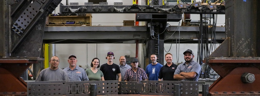
The future of full-scale structures testing and product development is here – and it is BIG. Our Tyrell Gilb Research Laboratory built a brand-new Million Pound Rig to help in the testing of our new Yield-Link® brace connection (YLBC), along with our many other products. Hear from Mike Wesson, Engineering Manager, Tyrell Gilb Research Laboratory, about this latest addition to the research lab.
Category: Testing/R&D
Simpson Strong-Tie is constantly testing and innovating.
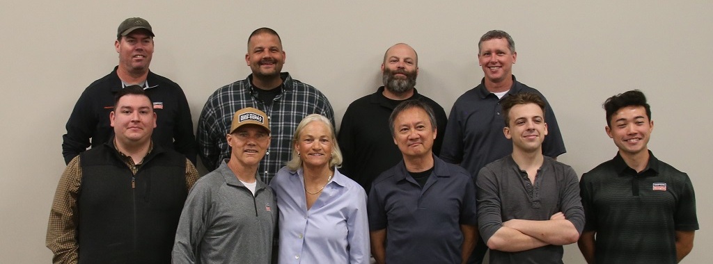
From CEO to Legacy: Welcome to the Karen Colonias Research Lab!
David Huerta, Senior Lab Manager at the Simpson Strong-Tie home office in Pleasanton, California, was present during the renaming of the Karen Colonias Research Laboratory. The lab was renamed in honor of our former CEO, Karen Colonias, who was instrumental in driving our company forward during her 38 years with the company, including 11 as our CEO. David shares his perspective on the lab’s functions and operations, as well as its importance to our company’s legacy.

Take a Tour of Our McKinney R&D Lab
Did you know that Simpson Strong-Tie has a research and development lab in our McKinney, Texas, branch? In the following article, Francisco, the McKinney branch lab manager, talks about the history of this lab and what we do there.

Good Ideas Come from Many Places — “Necessity Is the Mother of Invention”
You never know where the next great product idea or innovation is going to come from — some of our best new ideas originate with the customers who use our current products. At Simpson Strong-Tie, we welcome any inspiration that can help us serve our customers’ needs even better. With so much competition, however, and because so much research and testing are entailed in developing each new product, the criteria that an idea must meet to gain eventual acceptance are necessarily quite rigorous. In this post, Steve Rotzin, Manager of Intellectual Property and Legal Services at Simpson Strong-Tie, outlines some of these criteria for your consideration.
All of us, at one time or another, dream up a product idea of some sort. My wife was once sanding the tongue-and-groove boards of our living room ceiling and she thought of a very cool idea of gloves that had Velcro on them and users could interchange sandpaper of various grit on any finger of the glove. If you’ve ever sanded anything, this actually made a lot of sense especially for complex shapes and tough to reach spots. I researched it and found out that someone had already thought of it and “patented it.”
Continue Reading

Designing Resilience: NEESWood Capstone a Decade Later
In 2009, Simpson Strong-Tie participated in an unprecedented research event to highlight the importance of earthquake-resistant wood construction.
The event, the world’s largest earthquake test, was a collaborative Network for Earthquake Engineering Simulation project. It teamed academics, engineers, and industry researchers from around the world to subject a structure to what engineers refer to as the “maximum considered event” (MCE), a large, rare earthquake projected to occur, on average, approximately every 2500 years.
Continue Reading
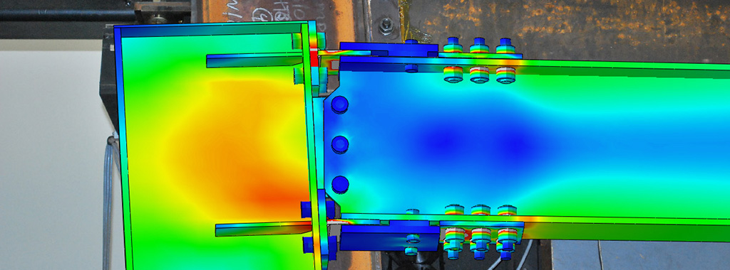
How Computer Simulation Can Power Innovation
Computer-simulated product testing is being used increasingly in modern engineering and manufacturing because it provides a low-risk, time- and cost-efficient means of modeling system performance using a wide array of variables before a physical prototype has been created. The following Blog post outlines some of the uses and advantages of integrating this technology into the product development process.Continue Reading

What You Need to Know About Differences in Wind-Speed Reporting for Hurricanes
There is a great deal of good information out there to help us better understand hurricanes and their impact on people, structures and other property. To improve awareness of wind speeds and their measurement, this article will discuss a commonly misunderstood aspect of hurricane wind-speed reporting.
Continue Reading
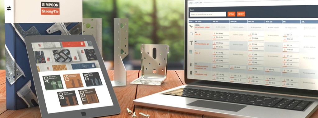
The Top 5 Helpful Tips for Using CFS Designer™ to Optimize Your Workflows
Back in April of last year, I had the opportunity to show how our new CFS Designer software could help structural engineers “go lean” in their design process by eliminating repetitive tasks (while still meeting required design standards, of course!). Since then, I’ve had the opportunity to visit with hundreds of engineers in person to teach them about CFS Designer and how it can help them improve and optimize their workflows. As a power user of the software, I want to share my top tips for letting CFS Designer help you save the maximum amount of time.
Continue Reading

Top 10 Changes to Structural Requirements in the 2018 IBC
This blog post will continue our series on the final results of the 2016 ICC Group B Code Change Hearings, and will focus on 10 major approved changes, of a structural nature, to the International Building Code (IBC).
- Adoption of ASCE 7-16
- The IBC wind speed maps and seismic design maps have been updated.
- A new section has been added to Chapter 16 to address tsunami loads.
- Table 1607.1 has been revised to change the deck and balcony Live Loads to 1.5 times that of the occupancy served.
- New and Updated Reference Standards
- 2015 IBC Standard ACI 530/ASCE 5/TMS 402-13 will be TMS402-16.
- ACI 530.1/ASCE 6/TMS 602-13 will be TMS 602-16.
- AISC 341-10 and 360-10 have both been updated to 2016 editions.
- AISI S100-12 was updated to the 2016 edition.
- AISI S220-11 and S230-07 were updated to the 2015 edition.
- AISI S200, S210, S211, S212 and S214 have been combined into a new single standard, AISI S240-15.
- AISI S213 was split into the new S240 and AISI S400-15.
- ASCE 41-13 was updated to the 2017 edition.
- The ICC 300 and ICC 400 were both updated from 2012 editions to 2017 editions.
- ANSI/NC1.0-10 and ANSI/RD1.0-10 were all updated to 2017 editions.
- Section 1607.14.2 Added for Structural Stability of Fire Walls
- This new section takes the 5 psf from NFPA 221, so designers will have consistent guidance on how to design fire walls for stability without having to buy another standard.
- Modifications of the IBC Special Inspections Approved
- Section 1704.2.5 on special inspection of fabricated items has been clarified and streamlined.
- The Exception to 1705.1.1 on special inspection of wood shear walls, shear panels and diaphragms was clarified to say that special inspections are not required when the specified spacing of fasteners at panel edges is more than 4 inches on center.
- The special inspection requirements for structural steel seismic force-resisting systems and structural steel elements in seismic force-resisting systems were clarified by adding exceptions so that systems or elements not designed in accordance with AISC 341 would not have to be inspected using the requirements of that standard.
- Changes Pertaining to Storm Shelters
- A new Section 1604.11 states that “Loads and load combinations on storm shelters shall be determined in accordance with ICC 500.”
- An exception was added stating that when a storm shelter is added to a building, “the risk category for the normal occupancy of the building shall apply unless the storm shelter is a designated emergency shelter in accordance with Table 1604.5.”
- Further clarification in Table 1604.5 states that the type of shelters designated as risk category IV are “Designated emergency shelters including earthquake or community storm shelters for use during and immediately after an event.”
- Changes to the IBC Conventional Construction Requirements in Chapter 23
- The section on anchorage of foundation plates and sills to concrete or masonry foundations reorganized the requirements by Seismic Design Category (SDC) and added a new section on anchoring in SDC E. It also states that the anchor bolt must be in the middle third of the width of the plate and adds language to the sections on higher SDCs saying that if alternate anchor straps are used, they need to be spaced to provide equivalent anchorage to the specified 1/2″- or 5/8″-diameter bolts.
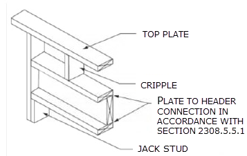
- The second change permits single-member 2-by headers, to allow more space for insulation in a wall.
- Modification to the Requirements for Nails and Staples in the IBC
- ASTM F1667 Supplement One was adopted that specifies the method for testing nails for bending-yield strength and identifies a required minimum average bending moment for staples used for framing and sheathing connections.
- Stainless-steel nails are required to meet ASTM F1667 and use Type 302, 304, 305 or 316 stainless steel, as necessary to achieve the corrosion resistance assumed in the code.
- Staples used with preservative-treated wood or fire-retardant-treated wood are required to be stainless steel.
- The new RSRS-01 nail was incorporated into TABLE 2304.10.1, the Fastening Schedule. The RSRS nail is a new roof sheathing ring shank nail designed to achieve higher withdrawal resistances, in order to meet the new higher component and cladding uplift forces of ASCE 7-16.
- Truss-Related Code Change
- The information required on the truss design drawings was changed from “Metal connector plate type” to “Joint connection type” in recognition that not all trusses use metal connector plates.
- Code Change to Section 2304.12.2.2
- A code change clarifies in which cases posts or columns will not be required to consist of naturally durable or preservative-treated wood. This change makes the requirements closer to the earlier ones, while maintaining consistency with the subsequent section on supporting members.
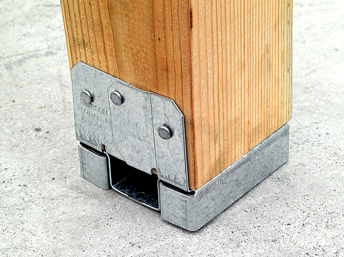
- If a post or column is not naturally durable or preservative-treated, it will have to be supported by concrete piers or metal pedestals projecting at least 1″ above the slab or deck, such as Simpson Strong-Tie post bases that have a one-inch standoff.
- Code Change to IBC Appendix M
- A code change from FEMA makes IBC Appendix M specific to refuge structures for vertical evacuation from tsunami, and the tsunami hazard mapping and structural design guidelines of ASCE 7-16 would be used rather than those in FEMA P-646.


Once the 2018 IBC is published in the fall, interested parties will have only a few months to develop code changes that will result in the 2021 I-Codes. Similar to this last cycle, code changes will be divided into two groups, Group A and Group B, and Group A code changes are due January 8, 2018. The schedule for the next cycle is already posted here.
What changes would you like to see for the 2021 codes?
Revisiting Spanning the Gap

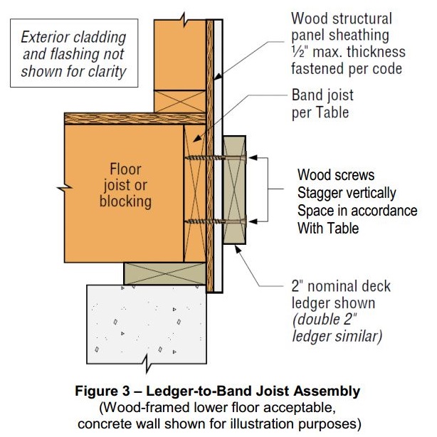
Three years ago, we created this blog post based on a technical support question we often receive about allowable fastener loads for ledgers to wood framing over gypsum board. Given that this is still a frequent question and a relevant topic, we decided to revisit the post and update it.
Drywall. Wall board. Sheetrock. Sackett Board? A product called Sackett Board was invented in the 1890s, which was made by plastering within wool felt paper. United States Gypsum Corporation refined Sackett Board for several years until 1916, when they developed a new method of producing boards with a single layer of plaster and paper. This innovation was eventually branded SHEETROCK®. More details about the history of USG can be found here.
No matter what you call it, gypsum board is found in almost every type of construction. Architects use it for sound and fire ratings, while structural engineers need to account for its weight in our load calculations. A common technical support question we receive is for allowable fastener loads for ledgers to wood framing over gypsum board.
One method to evaluate a fastener spanning across gypsum board is to treat the gypsum material as an air gap. Technical Report 12, General Dowel Equations for Calculating Lateral Connection Values, is published by the American Wood Council.

TR12 has yield limit equations that allow a designer to account for a gap between the main member and side member of a connection. With a gap of zero (g=0), the TR12 equations provide the same results as the NDS yield limit equations.
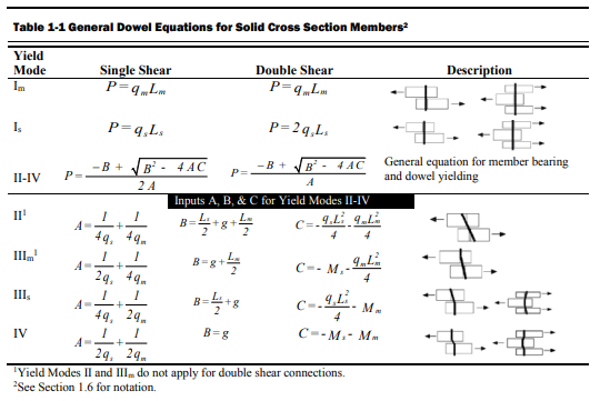
The equations are fairly complex, but it should be intuitive that the calculated fastener capacity decreases with increasing gap. Engineers are often surprised to see a 40, 50, even 60% drop in fastener capacity with one layer of 5/8” gypsum board. So what else can you do?
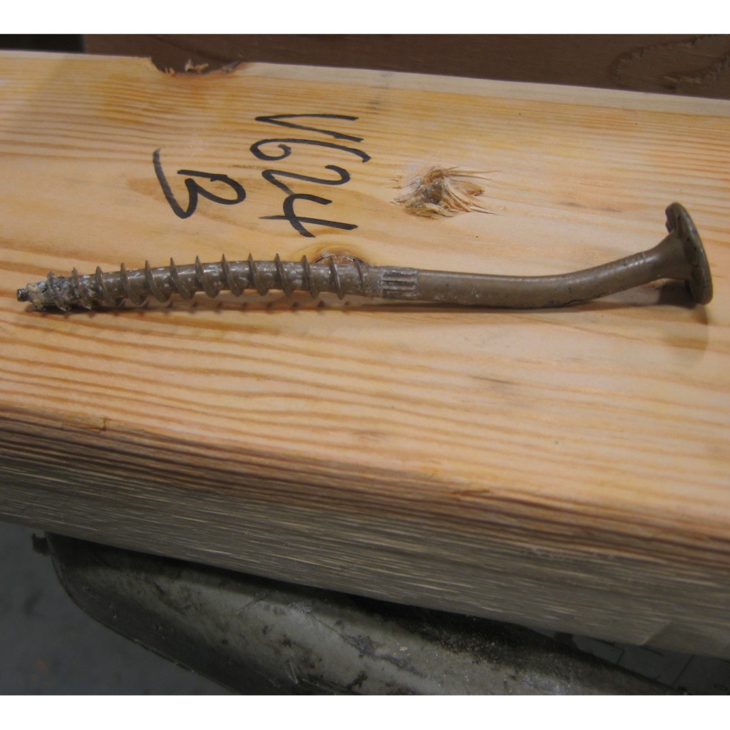
Testing, of course! In So, What’s Behind a Screw’s Allowable Load? I discussed the methods used to load rate a proprietary fastener such as the Simpson Strong-Tie® Strong-Drive® SDS or SDW screws. To recap, ICC-ES Acceptance Criteria for Alternate Dowel Type Fasteners, AC233, allows you to calculate and do verification tests, or load rate based on testing alone. We develop our allowable loads primarily by testing, as the performance enhancing features and material optimizations in our fasteners are not addressed by NDS equations.
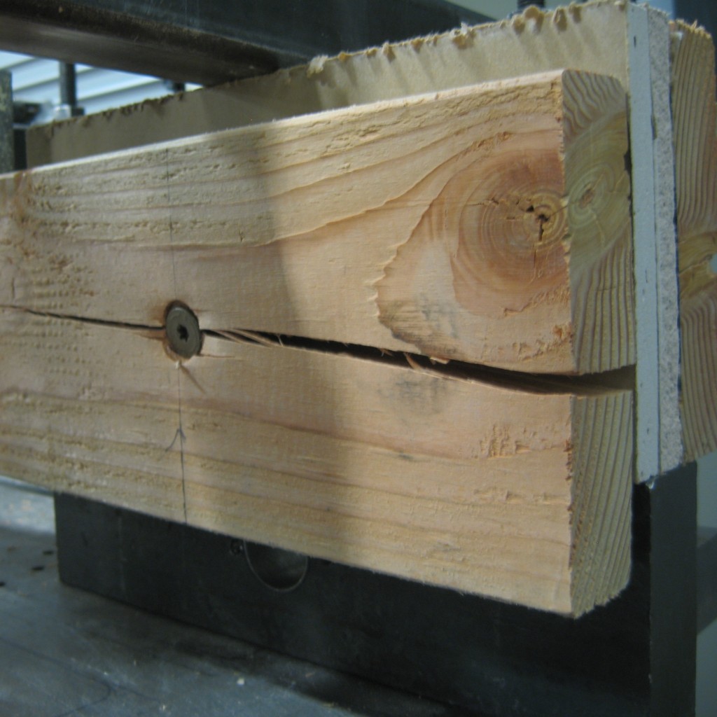
So to determine the performance of a fastener installed through gypsum board, we tested the fastener through gypsum board. This is easier to do if you happen to have a test lab with a lot of wood and fasteners in it. We did have to run down to the local hardware store to pick up gypsum board for the testing.
A full set of allowable loads for Strong-Drive SDWH and SDWS are available on strongtie.com. The information is given as single fastener shear values for engineered design, and also screw spacing tables for common ledger configurations. As much fun as writing spreadsheets to do the Technical Report 12 calculations is, having tabulated values based on testing is much easier.
Fastening Systems
In the fastener marketplace, Simpson Strong-Tie stands apart from the rest. Quality and reliability is our top priority.