Back in April of last year, I had the opportunity to show how our new CFS Designer software could help structural engineers “go lean” in their design process by eliminating repetitive tasks (while still meeting required design standards, of course!). Since then, I’ve had the opportunity to visit with hundreds of engineers in person to teach them about CFS Designer and how it can help them improve and optimize their workflows. As a power user of the software, I want to share my top tips for letting CFS Designer help you save the maximum amount of time.
Continue Reading

Q&A About Advanced FRP Strengthening Design Principles
Our thoughts go out to everyone affected by Hurricane Harvey and this disaster in Texas. To help with relief efforts we are donating $50,000 to the American Red Cross Disaster Relief Fund. Employees at our Houston warehouse are safe and the employees from our McKinney branch will be doing as much as they can to help with relief efforts.
On July 25, 2017, Simpson Strong-Tie hosted the second interactive webinar in the Simpson Strong-Tie FRP Best Practices Series, “Advanced FRP Design Principles,” in which Kevin Davenport, P.E. – one of our Field Engineering Managers – and I discussed the best practices for fiber-reinforced polymer (FRP) strengthening design. The webinar examines the latest industry standards, proper use of material properties, and key governing limits when designing with FRP and discusses the assistance and support Simpson Strong-Tie Engineering Services offers from initial project assessment to installation. Watch the on-demand webinar and earn PDH and CEU credits here.Continue Reading
Meet the First Simpson Strong-Tie Engineering Excellence Fellow with Build Change
![]()
Introducing James P. Mwangi, Ph.D., P.E., S.E. – our first annual Simpson Strong-Tie Engineering Excellence Fellow with Build Change. James Mwangi will write a quarterly blog about his experience throughout the Fellowship.
I’m delighted to have been asked to contribute this post and feel honored to be the first-ever Simpson Strong-Tie Engineering Excellence Fellow with Build Change. It’s my hope that this post will inform you about my professional background, why I applied to the Fellowship and how I think the Fellowship can benefit people and the structures they live, work and go to school in.
Continue Reading
Top 10 Changes to Structural Requirements in the 2018 IBC
This blog post will continue our series on the final results of the 2016 ICC Group B Code Change Hearings, and will focus on 10 major approved changes, of a structural nature, to the International Building Code (IBC).
- Adoption of ASCE 7-16
- The IBC wind speed maps and seismic design maps have been updated.
- A new section has been added to Chapter 16 to address tsunami loads.
- Table 1607.1 has been revised to change the deck and balcony Live Loads to 1.5 times that of the occupancy served.
- New and Updated Reference Standards
- 2015 IBC Standard ACI 530/ASCE 5/TMS 402-13 will be TMS402-16.
- ACI 530.1/ASCE 6/TMS 602-13 will be TMS 602-16.
- AISC 341-10 and 360-10 have both been updated to 2016 editions.
- AISI S100-12 was updated to the 2016 edition.
- AISI S220-11 and S230-07 were updated to the 2015 edition.
- AISI S200, S210, S211, S212 and S214 have been combined into a new single standard, AISI S240-15.
- AISI S213 was split into the new S240 and AISI S400-15.
- ASCE 41-13 was updated to the 2017 edition.
- The ICC 300 and ICC 400 were both updated from 2012 editions to 2017 editions.
- ANSI/NC1.0-10 and ANSI/RD1.0-10 were all updated to 2017 editions.
- Section 1607.14.2 Added for Structural Stability of Fire Walls
- This new section takes the 5 psf from NFPA 221, so designers will have consistent guidance on how to design fire walls for stability without having to buy another standard.
- Modifications of the IBC Special Inspections Approved
- Section 1704.2.5 on special inspection of fabricated items has been clarified and streamlined.
- The Exception to 1705.1.1 on special inspection of wood shear walls, shear panels and diaphragms was clarified to say that special inspections are not required when the specified spacing of fasteners at panel edges is more than 4 inches on center.
- The special inspection requirements for structural steel seismic force-resisting systems and structural steel elements in seismic force-resisting systems were clarified by adding exceptions so that systems or elements not designed in accordance with AISC 341 would not have to be inspected using the requirements of that standard.
- Changes Pertaining to Storm Shelters
- A new Section 1604.11 states that “Loads and load combinations on storm shelters shall be determined in accordance with ICC 500.”
- An exception was added stating that when a storm shelter is added to a building, “the risk category for the normal occupancy of the building shall apply unless the storm shelter is a designated emergency shelter in accordance with Table 1604.5.”
- Further clarification in Table 1604.5 states that the type of shelters designated as risk category IV are “Designated emergency shelters including earthquake or community storm shelters for use during and immediately after an event.”
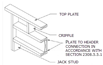
- Changes to the IBC Conventional Construction Requirements in Chapter 23
- The section on anchorage of foundation plates and sills to concrete or masonry foundations reorganized the requirements by Seismic Design Category (SDC) and added a new section on anchoring in SDC E. It also states that the anchor bolt must be in the middle third of the width of the plate and adds language to the sections on higher SDCs saying that if alternate anchor straps are used, they need to be spaced to provide equivalent anchorage to the specified 1/2″- or 5/8″-diameter bolts.
- The second change permits single-member 2-by headers, to allow more space for insulation in a wall.
- Modification to the Requirements for Nails and Staples in the IBC
- ASTM F1667 Supplement One was adopted that specifies the method for testing nails for bending-yield strength and identifies a required minimum average bending moment for staples used for framing and sheathing connections.
- Stainless-steel nails are required to meet ASTM F1667 and use Type 302, 304, 305 or 316 stainless steel, as necessary to achieve the corrosion resistance assumed in the code.
- Staples used with preservative-treated wood or fire-retardant-treated wood are required to be stainless steel.
- The new RSRS-01 nail was incorporated into TABLE 2304.10.1, the Fastening Schedule. The RSRS nail is a new roof sheathing ring shank nail designed to achieve higher withdrawal resistances, in order to meet the new higher component and cladding uplift forces of ASCE 7-16.
- Truss-Related Code Change
- The information required on the truss design drawings was changed from “Metal connector plate type” to “Joint connection type” in recognition that not all trusses use metal connector plates.
- Code Change to Section 2304.12.2.2
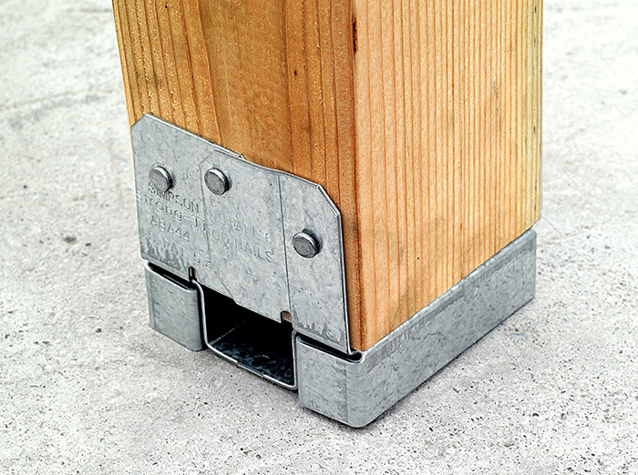
- A code change clarifies in which cases posts or columns will not be required to consist of naturally durable or preservative-treated wood. This change makes the requirements closer to the earlier ones, while maintaining consistency with the subsequent section on supporting members.
- If a post or column is not naturally durable or preservative-treated, it will have to be supported by concrete piers or metal pedestals projecting at least 1″ above the slab or deck, such as Simpson Strong-Tie post bases that have a one-inch standoff.
- Code Change to IBC Appendix M
- A code change from FEMA makes IBC Appendix M specific to refuge structures for vertical evacuation from tsunami, and the tsunami hazard mapping and structural design guidelines of ASCE 7-16 would be used rather than those in FEMA P-646.


Once the 2018 IBC is published in the fall, interested parties will have only a few months to develop code changes that will result in the 2021 I-Codes. Similar to this last cycle, code changes will be divided into two groups, Group A and Group B, and Group A code changes are due January 8, 2018. The schedule for the next cycle is already posted here.
What changes would you like to see for the 2021 codes?
Keep Your Roof On
He huffed, and he puffed, and he blew the roof sheathing off! That’s not the way kids’ tale goes, but the dangers high winds pose to roof sheathing are very real. Once the roof sheathing is gone, the structure is open and its contents are exposed to the elements and much more vulnerable to wind or water damage. It is a storyline that we meet all too often in the news.
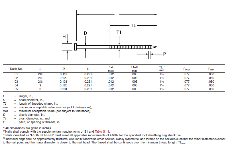
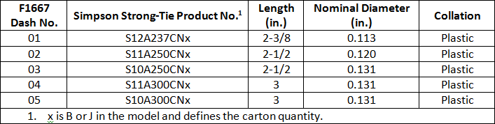
About two years ago, the ASTM subcommittee on Driven and Other Fasteners (F16.05), addressed fastening for roof sheathing in high-wind areas by adding a special nail to ASTM F1667-17 – Standard Specification for Driven Fasteners: Nails, Spikes and Staples. The Roof Sheathing Ring-Shank Nail was added to the standard as Table 46. Figure 1 illustrates the nail and lists its geometrical specifications. This is a family of five ring-shank nails that can be made from carbon steel or stainless steel (300 series). Specific features of these nails are the ring pitch (number of rings per inch), the ring diameter over the shank, the length of deformed shank and the head diameter. Also, note B specifies that the nails shall comply with the supplementary requirement of Table S1.1, which tabulates bending yield strength. In this diameter class, the minimum bending yield strength allowed is 100 ksi.
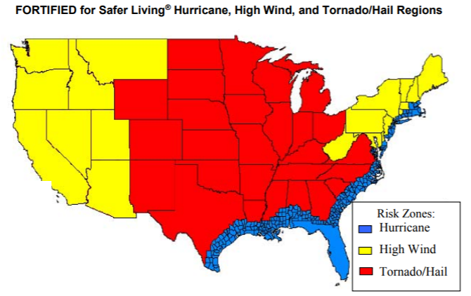
The IBHS (Insurance Institute for Business and Home Safety) discusses roof deck fastening in its Builders Guide that describes the “FORTIFIED for Safer Living” structures. The IBHS FORTIFIED program offers solutions that reduce building vulnerability to severe thunderstorms, hurricanes and tornadoes. Keeping the roof sheathing on the structure is critical to maintaining a safe enclosure and minimizing damage, and roof sheathing ring-shank nails can be part of the solution. As Figure 2 from IBHS (2008) shows, every wood-frame structure has wind vulnerability.
More importantly for the wood-frame engineering community, the Roof Sheathing Ring-Shank Nails are being included in the next revision of the AWC National Design Specification for Wood Construction (NDS-2018), which is a reference document to both the International Building Code and the International Residential Code. You will be able to use the same NDS-2018, chapter 12 withdrawal equation to calculate the withdrawal resistance for Roof Sheathing Ring-Shank Nails and Post Frame Ring-Shank nails. The calculated withdrawal will be based on the length of deformed shank embedded in the framing member. Also, Designers need to consider the risk of nail head pull-through when fastening roof sheathing with ring-shank nails. If the pull-through for roof sheathing ring-shank nails is not published, you will be able to use the new pull-through equation in the NDS-2018 to estimate that resistance.
Simpson Strong-Tie has some stainless-steel products that meet the requirements for Roof Sheathing Ring-Shank Nails. These will be especially important to those in coastal high-wind areas. Table 1 shows some of the Simpson Strong-Tie nails that can be used as roof sheathing ring-shank nails. These nails meet the geometry and bending yield strength requirements given in ASTM F1667. See the Fastening Systems catalog C-F-2017 for nails in Type 316 stainless steel that also comply with the standard.
Improve your disaster resilience and withstand extreme winds by fastening the sheathing with roof sheathing ring-shank nails. You can find Roof Sheathing Ring-Shank nails in ASTM F1667, Table 46, and you will see them in the AWC NDS-2018, which will be available at the end of the year. Let us know your preferred fastening practices for roof sheathing.
What’s New in the ACI 440.2R-17?
 The wait is over. The ACI 440.2R-17 Guide for the Design and Construction of Externally Bonded FRP Systems for Strengthening Concrete Structures is now available. The following post will highlight some of the major changes represented by this version of the document.
It’s been a long road and countless committee hours to get from the last version of ACI 440.2R-08 to this document. While there are multiple smaller changes throughout the document, the most notable update is the addition of Chapter 13 – Seismic Strengthening.
The new seismic chapter addresses the following FRP strengthening scenarios:
- Section 13.3 – Confinement with FRP
- This section includes all of the following: general considerations; plastic hinge region confinement; lap splice clamping; preventative buckling of flexural steel bars.
- Section 13.4 – Flexural Strengthening
- The flexural capacity of reinforced concrete beams and columns in expected plastic hinge regions can be enhanced using FRP only in cases where strengthening will transfer inelastic deformations from the strengthened region to other locations in the member or the structure that are able to handle the ensuing ductility demands.
- Section 13.5 – Shear Strengthening
- To enhance the seismic behavior of concrete members, FRP can be used to prevent brittle failures and promote the development of plastic hinges.
- Section 13.6 – Beam-Column Joints
- This section covers a great deal of recent research on the design and reinforcement of beam-column joints.
- Section 13.7 – Strengthening Reinforced Concrete Shear Walls
- This section provides many recommendations for FRP strengthening of R/C shear walls.
Simpson Strong-Tie Can Help
We recognize that specifying Simpson Strong-Tie® Composite Strengthening Systems™ (CSS) is unlike choosing any other product we offer. Leverage our expertise to help with your FRP strengthening designs. Our experienced technical representatives and licensed professional engineers provide complimentary design services and support – serving as your partner throughout the entire project cycle.
For complete information regarding specific products suitable to your unique situation or condition, please visit strongtie.com/css or call your local Simpson Strong-Tie RPS Specialist at (800) 999-5099.
Upcoming Free Webinar: Advanced FRP Design Principles
Join us live on July 25 for the second interactive webinar in the Simpson Strong-Tie FRP Best Practices Series: Advanced FRP Design Principles. In this webinar we will highlight some very important considerations during the FRP design processes. This will include topics such as the latest industry standards, proper use of material properties, and key governing limits when designing with FRP. Attendees will also have an opportunity to pose questions to our engineering team during the event. Continuing educations units will be offered for attending this webinar.
Learn more: Webinar – Introducing Fabric-Reinforced Cementitious Matrix (FRCM)
In this free webinar we dive into some very important considerations including the latest industry standards, material properties and key governing limits when designing with FRCM.
Continuing education credits will be offered for this webinar.
Participants can earn one professional development hour (PDH) or 0.1 continuing education unit (CEU).
Revisiting Stainless-Steel Nail Calculations . . . .
Those of you who have been following the Simpson Strong-Tie SE Blog for a while may recall our 2013 blog post on the withdrawal resistance of stainless-steel nails. There have been several developments relating to that subject since that blog was posted, and we want to help you catch up.Continue Reading
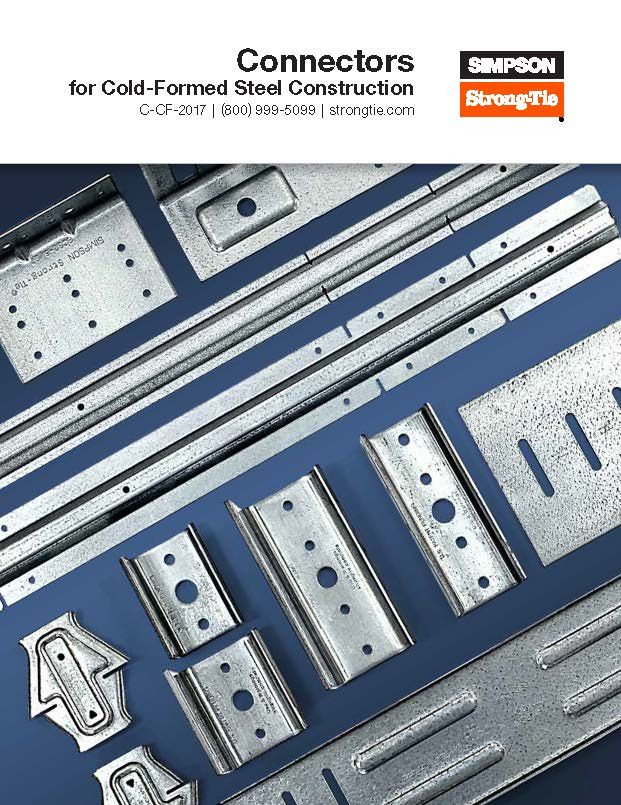
The Cold-Formed Steel Construction Catalog is HOT off the press!
The SE Blog is taking some time off for the 4th of July holiday this week. However, we’ve just released the 2017 edition of our Connectors for Cold-Formed Steel Construction catalog – order a hard copy to be mailed to your office or download a PDF copy and start using it today!
Connectors For Cold-Formed Steel Construction
The C-CF-2017 is a 308-page catalog including specifications, load tables and installation illustrations for our cold-formed steel connectors and clips, helping you easily specify and install in commercial curtain-wall, mid-rise and residential construction.
How Heat Treating Helps Concrete Anchoring Products Meet Tougher Load Demands
There’s a saying in Chicago, “If you don’t like the weather, just wait fifteen minutes.” That’s especially true in the spring, when temperatures can easily vary by over 50° from one day to the next. As the temperature plunges into the blustery 30s one evening following a sunny high in the 80s, I throw my jacket on over my T-shirt, and I’m reminded that large swings in temperature tend to bring about changes in behavior as well. This isn’t true just with people, but with many materials as well, and it brings to mind a thermal process called heat treating. This is a process that is used on some concrete anchoring products in order to make them stronger and more durable. You may have heard of this process without fully understanding what it is or why it’s useful. In this post, I will try to scratch the surface of the topic with a very basic overview of how heat treating is used to improve the performance of concrete anchors.Continue Reading
Revisiting Spanning the Gap

Three years ago, we created this blog post based on a technical support question we often receive about allowable fastener loads for ledgers to wood framing over gypsum board. Given that this is still a frequent question and a relevant topic, we decided to revisit the post and update it.
Drywall. Wall board. Sheetrock. Sackett Board? A product called Sackett Board was invented in the 1890s, which was made by plastering within wool felt paper. United States Gypsum Corporation refined Sackett Board for several years until 1916, when they developed a new method of producing boards with a single layer of plaster and paper. This innovation was eventually branded SHEETROCK®. More details about the history of USG can be found here.
No matter what you call it, gypsum board is found in almost every type of construction. Architects use it for sound and fire ratings, while structural engineers need to account for its weight in our load calculations. A common technical support question we receive is for allowable fastener loads for ledgers to wood framing over gypsum board.
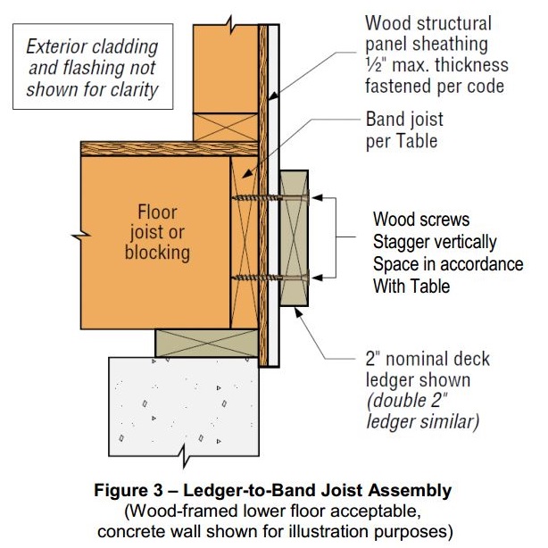
One method to evaluate a fastener spanning across gypsum board is to treat the gypsum material as an air gap. Technical Report 12, General Dowel Equations for Calculating Lateral Connection Values, is published by the American Wood Council.

TR12 has yield limit equations that allow a designer to account for a gap between the main member and side member of a connection. With a gap of zero (g=0), the TR12 equations provide the same results as the NDS yield limit equations.
![Technical Report 12 Yield Limit Equations[1]](http://seblog.strongtie.com/wp-content/uploads/2014/01/Technical-Report-12-Yield-Limit-Equations1.jpg)
Testing, of course! In So, What’s Behind a Screw’s Allowable Load? I discussed the methods used to load rate a proprietary fastener such as the Simpson Strong-Tie® Strong-Drive® SDS or SDW screws. To recap, ICC-ES Acceptance Criteria for Alternate Dowel Type Fasteners, AC233, allows you to calculate and do verification tests, or load rate based on testing alone. We develop our allowable loads primarily by testing, as the performance enhancing features and material optimizations in our fasteners are not addressed by NDS equations.
So to determine the performance of a fastener installed through gypsum board, we tested the fastener through gypsum board. This is easier to do if you happen to have a test lab with a lot of wood and fasteners in it. We did have to run down to the local hardware store to pick up gypsum board for the testing.
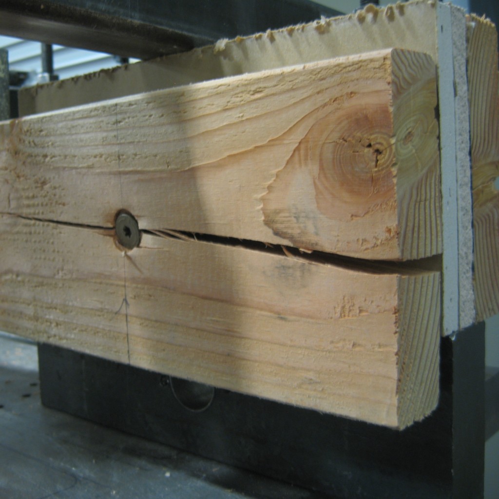
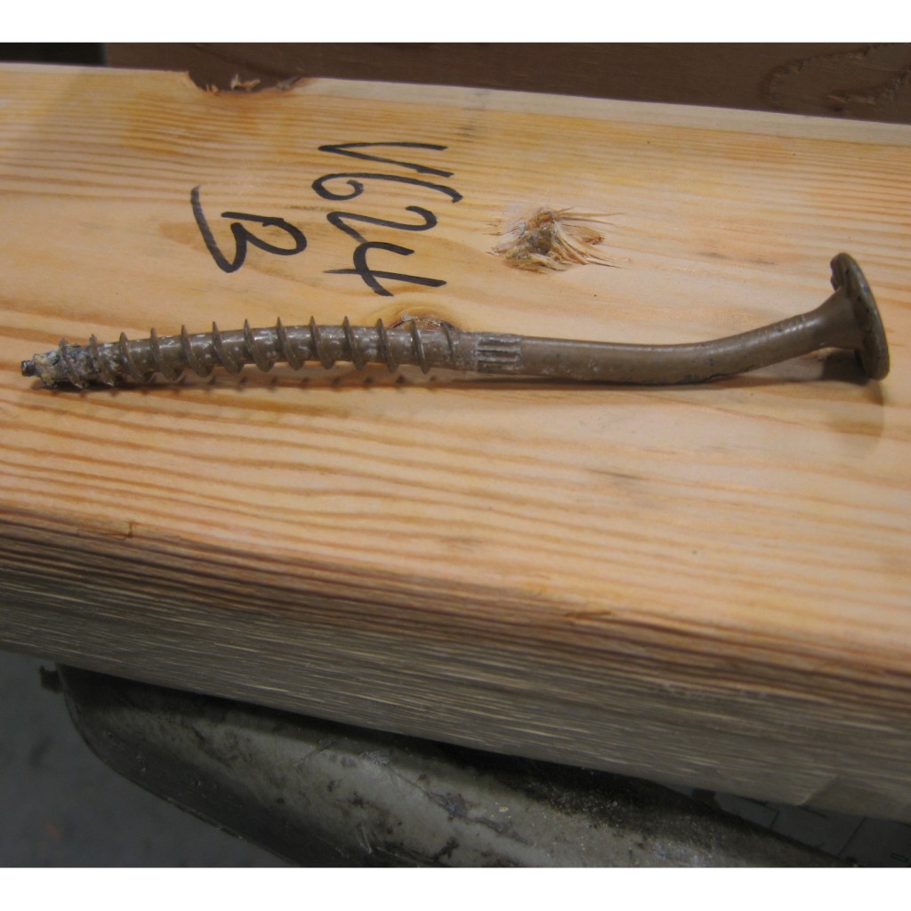
A full set of allowable loads for Strong-Drive SDWH and SDWS are available on strongtie.com. The information is given as single fastener shear values for engineered design, and also screw spacing tables for common ledger configurations. As much fun as writing spreadsheets to do the Technical Report 12 calculations is, having tabulated values based on testing is much easier.
Fastening Systems
In the fastener marketplace, Simpson Strong-Tie stands apart from the rest. Quality and reliability is our top priority.