Experiential learning — has it happened to you? Certainly it has, because experiential learning is learning derived from experience. It happens in everyday life, in engineering and in product development, too. For example, experience has taught us that after a product is launched, our customers will find applications for the product that were never expected or listed in the product brief. Also, experience has shown us that larger fasteners tend to be placed in applications that have greater structural and safety demands.
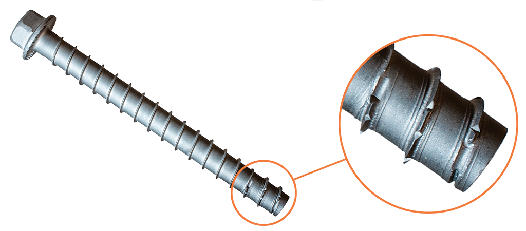
When the larger Deck-Drive™ DWP screws were manufactured, we decided that they should be marketed as “load-rated” screws because they were big enough to support physically large parts and would be expected to provide structural load resistance.
So what is a “load-rated” screw? To Simpson Strong-Tie, a load-rated screw is a threaded fastener that has controlled dimensions and physical properties, as well as validated connection properties. Load-rated fasteners are also subject to the same quality inspection that would occur if they were undergoing an evaluation report.
The primary benefit of fiber-reinforced polymer (FRP) systems as compared with traditional retrofit methods is that significant flexural, axial or shear strength gains can be realized using an easy-to-apply composite that does not add significant weight or section to the structure. Many times it is the most economical choice given the reduced preparation and labor costs and may be installed without taking the structure out of service. However, it is important to make sure the composite is properly designed following industry standards in order to ensure that it is the right product for the application.
To provide you with a better understanding of the topic, it’s important to dispel some common myths and misconceptions that you might hear about FRP:
For a structural engineer working on multiple projects in various stages of design and construction, it can be challenging to keep up to date on the latest industry trends. However, many of us in the construction industry enjoy learning about new construction techniques and unique projects. Being educated about new technology and design tools can also increase efficiency in the office.Continue Reading
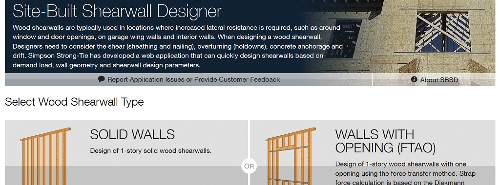
Wood shearwalls are typically used as a lateral-force-resisting system to counter the effects of lateral loads. Wood shearwalls need to be designed for shear forces (using sheathing and nailing), overturning (using holdowns), sliding (using anchorage to concrete) and drift, to list some of the main dangers. The Simpson Site-Built Shearwall Designer (SBSD) web app is a quick and easy tool to design a wood shearwall based on demand load, wall geometry and design parameters.Continue Reading
I was driving under a concrete bridge one nice clear day in Chicago, and I happened to look up to see rusted rebar exposed below a concrete bridge. My beautiful wife, who is not a structural engineer, turned to me and asked, “What happened to that bridge?” I explained that there are many reasons why spalling occurs below a bridge. One common reason is the expansion of steel when it rusts or corrodes.
When it comes to choosing a training facility, there are many well-researched principles about what makes an environment conducive to improved adult learning.
While we try to hold all training events in facilities that meet most of these principles, (even when traveling to our customers or users means we have to conduct events in hotel meeting rooms) we prefer to host you at our own locations.
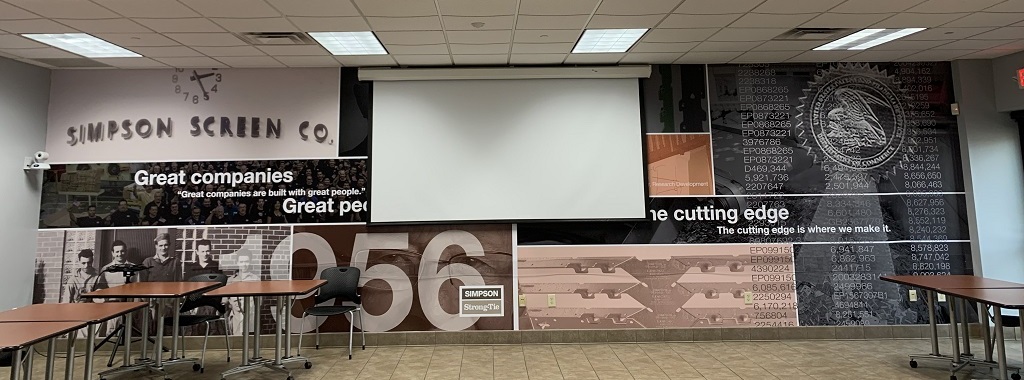
To this end, we invest a tremendous amount of time and resources to build and offer dedicated training facilities across the country. These facilities meet all the basic requirements for improved adult learning, but much more as well.
By having our own dedicated training facilities, we can provide learners with a much richer experience and contextually relevant displays.
These displays include partially deconstructed wall segments, foundations and roof systems that give learners a bigger picture of the applications being studied.
Many displays allow for hands-on installations and exercises that allow for improved comprehension of the product use and limitations. Even for the engineering community, who typically are limited to images from a catalog, the hands-on activities add great value. It’s always interesting to see the reaction that engineers have to actually seeing a system approach and having an opportunity to participate in learning that goes way beyond sitting and listening to a lecture.
Sometimes learners just need to see, feel or hold something in order to really understand a concept or product application. We make every effort to bring legitimate educational content to our workshops, supported by products that we hope will furnish solutions to your needs.
Many of our facilities include a plant tour and/or testing-facility tour as well. While these components don’t always align directly with the learning objectives, they do offer a chance for our guests to raise their energy levels and get a better understanding of that scale, capabilities, and commitment to quality that we bring to bear in our endeavor to help people build safer structures.
Additionally, we offer our facilities to customers, associations and industry organizations to use for their own meetings and training events. If you haven’t been to one of our workshops or visited one of our facilities, I highly encourage you to join the 35,000 plus who have over the last four years. You can find a complete list of workshops on our training home page. I expect that you’ll find it an educational and highly engaging experience that helps you build safer structures as well.
How would a six-story light-frame wood building perform in a large earthquake? Back in 2009, Simpson Strong-Tie was a partner in the World’s Largest Earthquake Test, a collaboration of the NEESWood project, to answer that question. This was a full-scale test which subjected the building to 180% of the Northridge earthquake ground motions (approximately a M7.5). Within the building, Simpson Strong-Tie connectors and Strong-Frame SMF were used, with the Strong-Rod™ anchor tiedown system (ATS) serving as holdown for each shearwall.
The NEESWood building was designed under Performance-Based Design methodology, and the test was conducted as validation for the approach. Buildings of similar size to the NEESWood building are built to current codes using similar products. Mid-rise light-frame wood structures continue to be a popular form of construction in various densely populated cities across the country. As part of the lateral-force-resisting system, continuous rod systems are used as the holdown for the shearwall overturning restraints. Simpson Strong-Tie has been involved with continuous rod systems since the early 2000s when we launched the Strong-Rod anchor tiedown system.
Today, rod manufacturers design the continuous rod systems with design requirements (loading, geometry, etc.) Supporting documents (e.g., installation details, layouts, RFI/markups and calculations) are submitted for each unique project. Over the years, engineers have asked many questions related to the design of these systems. In this week’s blog, we will explore Frequently Asked Questions pertaining to Strong-Rod ATS systems used as shearwall overturning restraints (holdowns).
The majority of these components are designed in accordance with the building code and reference standards (e.g., NDS, AISC). A project-specific calculation package is submitted for each job that addresses the evaluation of these elements. Therefore, these elements are not listed in evaluation reports.
Shrinkage compensation devices, on the other hand, are proprietary components which are not addressed by the building code or reference standards. Therefore, they are tested in accordance with ICC-ES acceptance criteria AC316 and are listed in ICC-ES ESR-2320.
What is the material specification of the rods used above concrete?
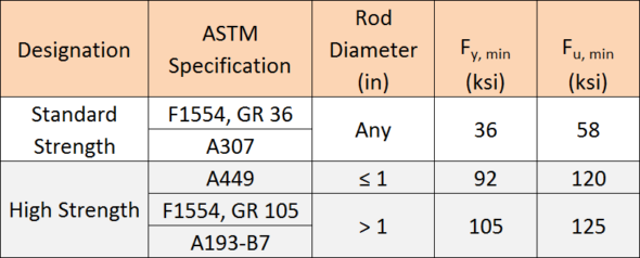
The specified rod materials are shown in Table 1.
Table 1. ATS Rod Material Specifications
Can threaded rods or couplers be welded to steel beams?
Simpson Strong-Tie generally does not recommend this practice. Of the materials listed in Table 1, ASTM A307 material is the only specification that contains supplementary requirements for welding. When standard strength rod is supplied to the job, it is not guaranteed that this will be the material provided.
ASTM A449 and A193-B7 high-strength rods develop strength and ductility characteristics through controlled quenching and tempering treatments. Quenching is the rapid cooling of metal (usually by water or oil) to increase toughness and strength. This process often increases brittleness. Tempering is a controlled reheating of the metal which increases ductility after the quenching process. Precise timing in the application of temperature during the tempering process is critical to achieving a material with well-balanced mechanical properties. It is unlikely that field welding will satisfy the requirements of quenching and tempering.
Coupler nuts are generally fabricated from material exhibiting characteristics similar to high-strength rods. Thus, it is not recommended to weld coupler nuts to steel beams due to the potential for embrittlement.
Simpson Strong-Tie specifies a weldable cage which is fabricated from ASTM A36 material for such applications.
How do you calculate the Maximum ASD Tension Capacity provided in the job summary?
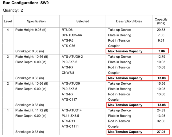
Simpson Strong-Tie provides a comprehensive design package for continuous rod systems used as holdowns for multi-story stacked shearwalls. The individual run calculations, as shown in Figure 1, provide the Maximum Tension Capacity, which correlates to the maximum force the system can deliver. Plan check often requests justification on how these values are derived at each level. These values are calculated, and the process explained below may be used on any Simpson Strong-Tie ATS Job Summary as justification.
Figure 1. Sample ATS Run Type SW9
The maximum tension capacity published within the Job Summary and the Installation Details is derived using the following procedure:
Step 1: Evaluate the top-most level. Compare the published capacities of the rod in tension, plate in bearing and the take-up device. The lowest of these three will govern and becomes the Maximum Tension Capacity for this level.
Step 2: Evaluate the next level down. (a) Sum the Maximum Tension Capacity from Step 1 and the published capacity of the take-up device from this level. (b) Sum the Maximum Tension Capacity from Step 1 and the published capacity of the plate in bearing from this level. (c) Compare derived values from (a) and (b) to the published capacity of rod in tension. The lowest of these three values will govern and becomes the Maximum Tension Capacity of this level.
Step 3: Repeat Step 2 as necessary until the bottom-most level is reached.
Applying this procedure to the sample run, SW9, will wield the following result:
Step 1: Evaluate capacities published at Level 4
Plate in bearing (PBRTUD5-6A) = 7.06 kipsgoverns
Take-up device (RTUD6) = 20.83 kips
Rod in tension (ATS-R6) = 9.61 kips
The lowest value in Step 1 is the plate in bearing, hence 7.06 kips is the maximum load that can be delivered at Level 4 and is the Maximum Tension Capacity.
Step 2: Evaluate capacities at Level 3
Maximum Tension Capacity from Level 4 = 7.06 kips (See Step 1)
Maximum Tension Capacity from Level 4 + take-up device (ATS-ATUD9-2) = 7.06 + 12.79 = 19.85 kips
Maximum Tension Capacity from Level 4 + plate in bearing (PL9-3×5.5) = 7.06 + 10.03 = 17.09 kips
Rod in tension (ATS-R7) = 13.08 kipsgoverns
The lowest value in Step 2 is the rod in tension, hence 13.08 kips is the maximum load that can be delivered at Level 3 and is the Maximum Tension Capacity.
Step 3: Evaluate capacities at Level 2
Maximum Tension Capacity from Level 3 = 13.08 kips (See Step 2)
Maximum Tension Capacity from Level 3 + take-up device (ATS-ATUD9-2) = 13.08 + 15.56 = 28.64 kips
Maximum Tension Capacity from Level 3 + plate in bearing (PL9-3×5.5) = 13.08 + 10.03 = 23.11 kips
Rod in tension (ATS-R7) = 13.08 kipsgoverns
The lowest value in Step 3 is the rod in tension, hence 13.08 kips is the maximum load that can be delivered at Level 2 and is the Maximum Tension Capacity.
Step 4: Evaluate capacities at Level 1
Maximum Tension Capacity from Level 2 = 13.08 kips (See Step 3)
Maximum Tension Capacity from Level 2 + take-up device (ATS-ATUD14) = 13.08 + 24.39 = 37.47 kips
Maximum Tension Capacity from Level 2 + plate in bearing (PL14-3×8.5) = 13.08 + 13.98 = 27.05 kipsgoverns
Rod in tension (ATS-R11) = 32.30 kips
The lowest value in Step 4 is due to the plate in bearing, hence 27.05 kips is the maximum load that can be delivered at Level 1 and is the Maximum Tension Capacity.
In the System Deflection Summary page(s) of the Job Summary, is the Total System Deflection provided at Allowable or Strength levels?
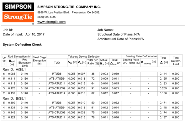
Immediately following the individual run calculations in each job summary, Simpson Strong-Tie provides a summary of deflection of the rod system similar to what is shown in Figure 2. This breaks down the deformation of all components being considered. In the example below, the rod elongation and deflection of the take-up device are summed to provide the total deflection.
The calculated system deflection is presented at ASD level. See section below for how to use these system deflections for your drift calculation.
Figure 2. Sample System Deflection Check
What system deflection limit do you typically design to, and what does that include?
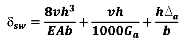
Unless otherwise specified on the plans or required by the building jurisdiction, Simpson Strong-Tie will design the continuous rod system to satisfy the deformation limits set forth in ICC-ES Acceptance Criteria (AC316). In some instances, the Designer may need a more restrictive deformation due to project specific conditions (e.g., tight building separations) and will require rod manufacturers to design for a lower deformation. Some jurisdictions (e.g., City of San Diego, City of San Francisco) may also have specific design requirements that continuous rod systems must conform to. The minimum recommended per-floor deformation limit set forth in AC316 is:
PD = ASD demand cumulative tension load (kips)
L = length of the rod between restraints – i.e., floor-to-floor (in.)
A = net tensile area of the rod (in.2)
E = Young’s Modulus of Elasticity (29,000 ksi)
ΔR = seating increment of the shrinkage compensation device (as published in ICC-ES evaluation report)
ΔA = deflection of the shrinkage compensation device at the allowable load (as published in ICC-ES evaluation report)
PA = Allowable capacity (kips)
Should deformation limits be specified in the construction documents?
Simpson Strong-Tie strongly recommends this information be included in the construction documents. Along with the cumulative tension and compression forces, the required deformation limits for the holdown are important to ensure that rod manufacturers are designing the holdown to satisfy the desired shearwall performance.
How do I use the system deformation limit?
The System Deflection is the total deformation of the holdown system from floor to floor (refer to the last two columns in Figure 2). This information represents the total ASD holdown deformation term, Δa, for each level and is to be used in the shearwall drift equation from the Special Design Provisions for Wind and Seismic (2015 SDPWS 4.3-1).
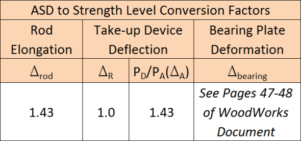
ASCE 12.8.6 requires that shearwall drift be calculated at strength level. Therefore, the information provided within the System Deflection Summary page needs to be converted from ASD to Strength Level. The conversion factors in Table 2 can be used to convert the ASD deformations to strength level. For discussions and methodology in converting bearing plate deformation to strength level, please refer to the WoodWorks Design Example of a Five-Story Wood Frame Structure over Podium Slab found here.
Table 2. ATS Rod Deflection ASD to LRFD Conversion Factors
Can rod systems be used in Type III construction?
Yes! 2015 IBC §2303.2.5 requires that Fire Retardant-Treated Wood (FRTW) design values be adjusted based on the type of treatment used on the project. Adjustment factors vary for each FRTW manufacturer; refer to the ICC-ES evaluation report of the specified FRTW manufacturer for the unique adjustment values. Rod manufacturers need to know what treatment is being used so this information can be taken into consideration when designing compression posts and incremental bearing (bearing plates).
What are Simpson Strong-Tie’s guidelines for fire caulking material?
While there are many options for fire-rated caulking, these products can be used in conjunction with the Simpson Strong-Tie ATS system. Below is a list of considerations when selecting and specifying a material for use where the rods penetrate the top and sole plates:
The fire-rated caulking shall not be corrosive to metal when used in contact with ATS components.
Direct contact with shrinkage compensating devices (e.g., TUD, ATUD, RTUD) shall be avoided. Shrinkage compensating devices have moving components and may not function properly with debris interference.
Indirect contact with shrinkage compensating devices shall also be avoided. Shrinkage compensation accumulates up the building and therefore the largest shrinkage occurs at the top of the building. As such, when the building shrinks, remnants of the material may still be stuck to the threads of the rod and may be detrimental to the performance of some shrinkage compensating devices (e.g., an RTUD). It is recommended to detail the installation with shrinkage taken into consideration.
The fire-rated caulking should be pliable to accommodate wood shrinkage and the building moving down during this process.
The performance and the suitability of fire-rated caulking are outside the scope of Simpson Strong-Tie.
Why doesn’t your design include compression post design?
If the Engineer of Record has already specified compression posts to be used with a continuous rod system, Simpson Strong-Tie will not provide these on the holdown installation drawings. This is primarily done to prevent discrepancies between the specification in the contract documents and what is shown on the installation drawings.
What is the maximum spacing between compression posts?
For platform-framed structures, the maximum spacing between compression posts is 9″. The large majority of Simpson Strong-Tie bearing plates will fit within the 9″ spacing requirement, eliminating the need for notching compression posts. In some framing conditions, such as balloon framing or a top chord bearing truss, the maximum spacing will be reduced to 6″. This is due to the limited amount of space between the top of the compression posts transferring uplift (via bearing) into the point of restraint (e.g., bearing plate) at the level above. To ensure this load path is complete, the posts need to be spaced closer.
What is the nailing schedule for the bridge block to the king studs?
Simpson Strong-Tie doesn’t recommend nailing the bridge block to the cripple as the bridge block member will shrink. Locking the bridge block in place may result in a gap forming between the bottom of the bridge block member and the top of the cripple studs, which is not accounted for in the Total System Deflection.
Are there any published documents with design examples of continuous rod systems used in mid-rise construction?
Another useful resource is published by WoodWorks and is a design example of a five-story wood-frame structure over podium slab. This document can be found here.
What questions do you have about the Strong-Rod ATS System? Leave them below.
This blog post continues our series on the final results of the 2016 ICC Group B Code Change Hearings. This post will focus on approved changes to the International Residential Code (IRC) that are of a structural nature. The changes outlined here will be contained in the 2018 IRC, which is expected to be published in the fall of this year.
In Chapter 3, the seismic design category / short-period design spectral response acceleration maps will be updated to match the new USGS/NEHRP Seismic Maps. These new maps are based on the worst case assumption for Site Class. Significantly, a new set of maps will be provided in Figure 301.2(3) “Alternate Seismic Design Categories”. These are permitted to be used when the “soil conditions are determined by the building official to be Site Class A, B or D.” See page 29 of the linked document for the new maps and a good explanation of the changes that will be occurring in various parts of the country. In addition, the ICC Building Code Action Committee authored a reorganization of the seismic provisions of Chapter 3 to try to reduce confusion.
Another change in Chapter 3 will clarify that guards are only required on those portions of walking surfaces that are located more than 30 inches above grade, not along the entire surface. To bring consistency with the IBC, another change will require that staples in treated wood be made of stainless steel.
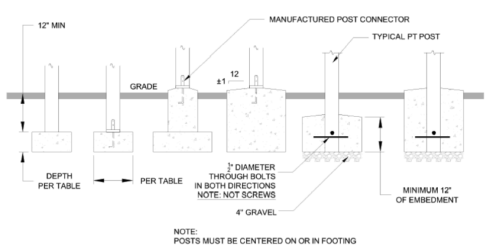
A broad group of parties interested in deck safety, known as the Deck Code Coalition, submitted 17 different code changes with revisions to Section R507 on decks. Of those, 12 were approved, making significant changes to that section. The various approved changes included the following: a complete re-write of that section; new/clarified requirements for deck materials, including wood, fasteners and connectors; clarified requirements for vertical and lateral connections of the deck to the supporting structure; new requirements for sizes of deck footings and specification that deck footings must extend below the frost line, with certain exceptions; clarification for deck board material, including an allowance for alternative decking materials and fastening methods; adding new columns to the deck joist span table that show the maximum cantilever for joists; adding the allowance for 8×8 deck posts, to allow notching for the support of a three-ply beam; and clarification of the deck-post-to-footing connection.
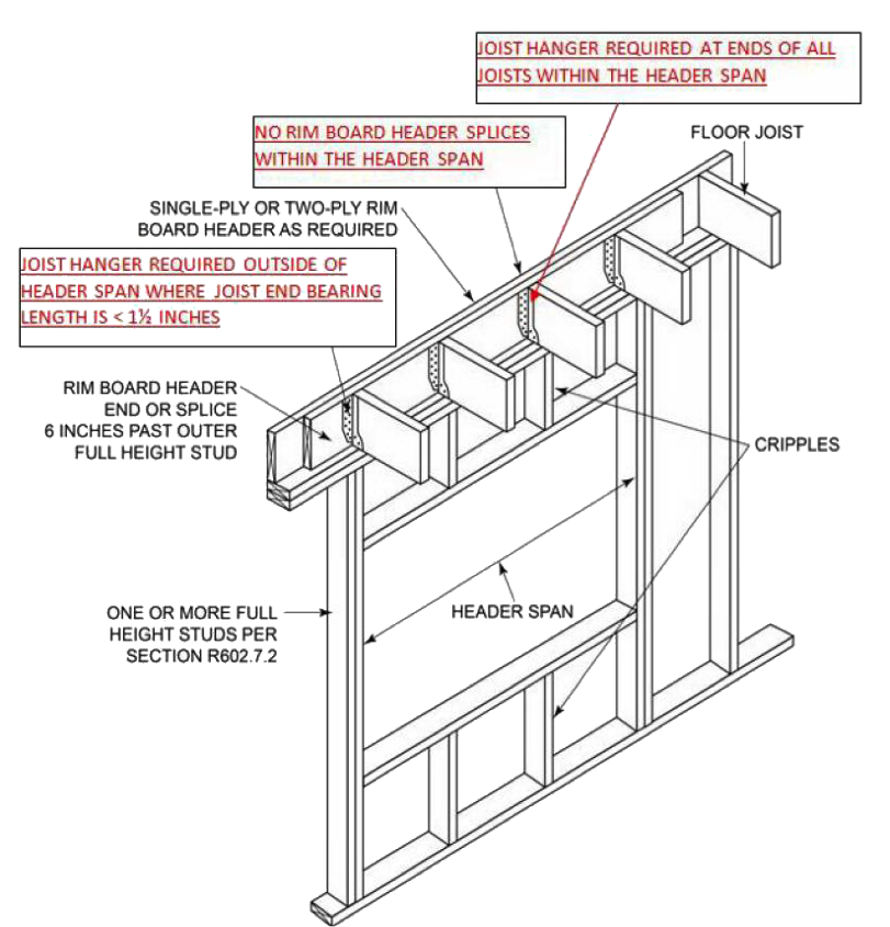
In Chapter 6, a new table permitting 11ʹ- and 12ʹ- long studs was added. In the 2015 IRC, load-bearing studs were limited to 10 feet in length. A new high-capacity nail, the RSRS (Roof Sheathing Ring Shank) nail was added as an option for fastening roof sheathing. This nail will become more widely used once the higher roof component and cladding forces from ASCE 7-16 are adopted. The rim board header detail that was added for the 2015 IRC was corrected to show that hangers are required in all cases when the joists occur over the wall opening.
There were several changes made to the Wall Bracing Section, R602.10. The use of the 2.0 increase factor was clarified for use when the horizontal joints in braced wall panel sheathing are not blocked. Narrow methods were added to the column headings for the wind and seismic bracing amount tables, to make them consistent, and the methods for adding different bracing were clarified. When using bracing method PFH, the builder can omit the nailing of the sheathing to the framing behind the strap-type holdown. Finally, offering some relief for high-seismic areas where brick veneer is used, an allowance was added to permit a limited amount of brick veneer to be present on the second floor without triggering the use of the BV-WSP bracing method.
In Chapter 8, the requirements for a “stick-framed” roof system were completely re-written to make such systems easier to use.
A couple of significant changes were made to the prescriptive requirements for cold-formed steel framing. The requirements for the anchorage of cold-formed steel walls were revised, and the wind requirements for cold-formed steel framing were changed to match the new AISI S230 prescriptive standard.
Finally, it may be helpful to mention some of the proposed changes that were not adopted. While the new ASCE 7-16 was adopted as the IRC reference standard for loads as part of the Administrative changes, several changes to the IRC to make it consistent with ASCE 7-16 were not approved. A change to update the IRC wind speed maps, roof component and cladding pressures, component and cladding roof zones, and revise the remainder of wind-based requirements to match ASCE 7-16 was not approved. Similarly, a proposal to increase the live load on decks, from 1.0 to 1.5 times the occupancy served, was denied.
Once the IRC is published, it will be time to start a new code change cycle once again, with Group A code changes due January 8, 2018. The schedule for the next cycle is already posted here.
What changes would you like to see for the 2021 codes?
One of the ways I get through winter every year is by looking forward to the weekend in March when we set our clocks ahead and “spring forward” into Daylight Savings time. Some people don’t like this change because of the lost hour of sleep, but to me it means the weather shouldn’t be cold for much longer.
The coming of spring means getting to walk to the car in daylight at the end of the workday. It also means getting the garden started for the year and spending more time outside in general.
Of course, I’m not alone in being happy to see winter go.
In the residential world, the phenomenon of “deck season” coincides with this time of year. Homeowners with decks are getting ready for summer by giving their decks a cleaning and looking them over for any needed maintenance. Now’s the time that new or replacement decks are being planned and built to be enjoyed for the rest of the year.
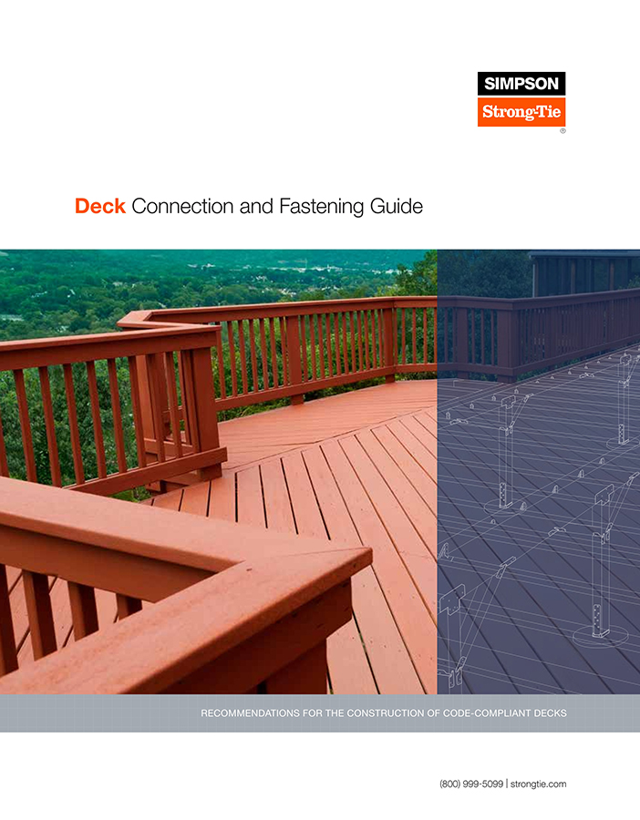
It’s no coincidence, then, that our deck-code guide has been updated again in time for warmer weather. The Deck Connection and Fastening Guide goes detail by detail (ledger connection, joist-to-beam connection, beam-to-post connection, etc.) through a typical deck and identifies the relevant building-code requirements (2012 and 2015 IRC/IBC) and connection options.
Our deck-code guide can be a helpful reference to an engineer who is just getting acquainted with decks, and can also bring you up to speed on revisions to the IRC that can necessitate engineering changes to even a relatively simple residential deck. Multilevel decks, guardrail details, ledger details and foundation challenges are all examples of things a deck builder could call you for assistance with.
This guide provides instructions on how to recognize defects and deficiencies in existing decks, and guidance for building a strong, safe, long-lasting new or renovated deck structures.
For more deck-related blog posts, check out the links below:
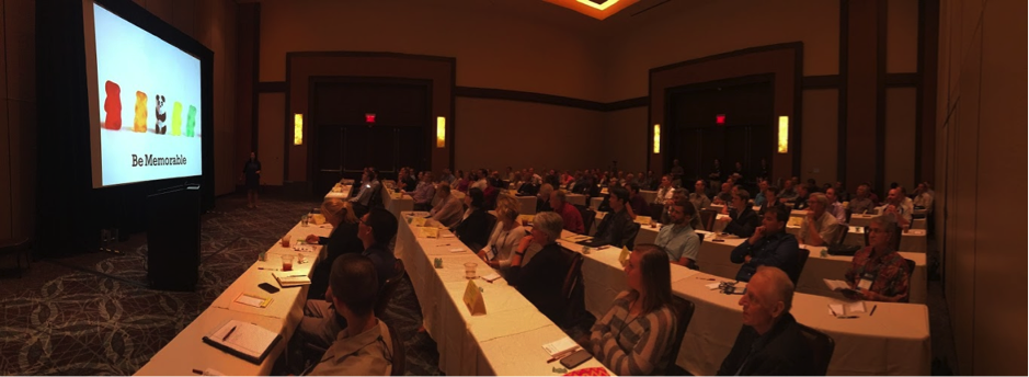
Last year, I gave a presentation at the annual National Council of Structural Engineers Associations (NCSEA) Summit in Orlando, Florida, titled “Becoming a Trusted Advisor: Communication and Selling Skills for Structural Engineers.” As this was a summit for the leaders of the structural engineers associations from across the country, I wasn’t sure how many people would find it valuable to spend their time learning about a very nontechnical topic. To my surprise and delight, the seminar ended up being standing-room only, and I was able to field some great questions from the audience about how they could improve their selling and communication skills. In the many conversations I had with the conference attendees after my presentation, the common theme was that engineers felt they needed more soft-skills training in order to better serve their clients. The problem, however, was finding the time to do so when faced with the daily grind of design work.
Presenting at the NCSEA Summit, I’m the tiny person in upper left hand corner.
When I started my first job as a design engineer at a structural engineering consulting firm straight out of school, I was very focused on improving and expanding my technical expertise. Whenever possible, I would attend building-code seminars, design reviews and new product solution presentations, all in an effort to learn more about structural engineering. What I found as I progressed through my career, however, was that no matter how much I learned or how hardworking I was, it didn’t really matter if I couldn’t successfully convey my knowledge or ideas to the person who really mattered most: the client.
Contractors discussing building plans with an engineer.
How can an engineer be most effective in explaining a proposed action or solution to a client? You have to be able to effectively sell your idea by understanding the needs of your client as well as any reasons for hesitation. The importance of effective communication and persuasion is probably intuitive to anyone who’s been on the sales side of the business, but not something that occurs naturally to data-driven folks like engineers. As a result of recent legislation in California, however, structural engineers are starting to be inundated with questions from a group of folks who have suddenly found themselves responsible for seismically upgrading their properties: apartment building owners in San Francisco and Los Angeles.
Imagine for a moment that you are a building owner who has received a soft-story retrofit notice under the City of Los Angeles’ Ordinance 183893; you have zero knowledge of structural engineering or what this term “soft-story” even means. Who will be your trusted advisor to help you sort it out? The City of Los Angeles Department of Building and Safety (LADBS) has put together a helpful mandatory ordinance website that explains the programs and also offers an FAQ for building owners that lets them know the first step in the process: hire an engineer or architect licensed in the state of California to evaluate the building.
Checking out some soft story buildings in Los Angeles. The Los Angeles Times has a great map tool.
I’ve had the opportunity to be the first point of contact for a building owner after they received a mandatory notice, because it turns out some relatives own an apartment building with soft-story tuck-under parking. Panicked by the notice, they called me looking to understand why they were being forced to retrofit a building that “never had any problems in the past.” They were worried they would lose rent money due to tenants needing to relocate, worried about how to meet the requirements of the ordinance and, most importantly, worried about how much it was going to cost them. What they really wanted was a simple, straightforward answer to their questions, and I did my best to explain the necessity behind retrofitting these vulnerable buildings and give an estimated time frame and cost that I had learned from attending the first Los Angeles Retrofit Resource Fair in April 2016. With close to 18,000 buildings in the cities of San Francisco and Los Angeles alone that have been classified as “soft-story,” this equates to quite a number of building owners who will have similar questions and be searching for answers.
Submitting Building Plans with the Right Retrofit Product Solutions
Communicating with Your Building Tenants
Completing Your Soft-Story Retrofit
We encourage you to invite any clients or potential clients to attend this informative webinar, which will lay the foundation for great communication between the two of you. As part of the webinar, we will be asking the building owners for their comments, questions and feedback so we can better understand what information they need to make informed decisions, and we will be sure to share these with the structural engineering community in a future post. By working together to support better communication and understanding among all stakeholders in retrofit projects, we will be well on our way to creating stronger and more resilient communities!
For additional information or articles of interest, there are several resources available:
We use cookies on this site to enhance your user experience. By clicking "I AGREE" below, you are giving your consent for us to set cookies. Privacy PolicyI AGREE
Privacy & Cookies Policy
Privacy Overview
This website uses cookies to improve your experience while you navigate through the website. Out of these cookies, the cookies that are categorized as necessary are stored on your browser as they are essential for the working of basic functionalities...
Necessary cookies are absolutely essential for the website to function properly. This category only includes cookies that ensures basic functionalities and security features of the website. These cookies do not store any personal information.
Any cookies that may not be particularly necessary for the website to function and is used specifically to collect user personal data via analytics, ads, other embedded contents are termed as non-necessary cookies. It is mandatory to procure user consent prior to running these cookies on your website.