

The Simpson Strong-Tie Strong-Wall® shearwall was introduced in 1999. The 1997 Uniform Building Code had incorporated restrictive 2:1 aspect ratio requirements for wood structural panel (WSP) shearwalls in high seismic areas. We conducted extensive cyclic testing of complete wall systems (not just components) to prove that narrow Strong-Wall shearwalls achieved the high performance required for seismic and wind designs.
Tag: ATS
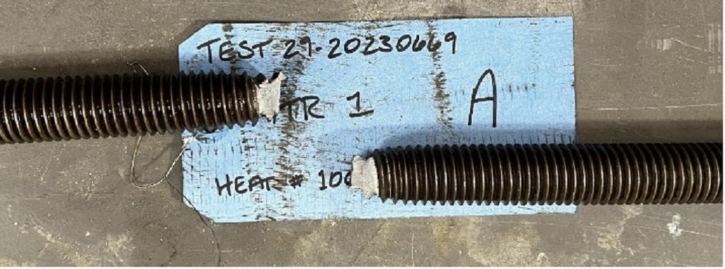
Rod Elongation: Use of Gross Area vs. Effective/Net Tensile Area
Within the world of multifamily construction, manufacturers design and detail the multistory continuous threaded rod holdowns used as shearwall overturning restraints. The Strong-Rod® anchor tiedown system (ATS) is Simpson Strong-Tie’s solution for the industry and has been the subject of many SE Blog topics in the past.

Simpson Strong-Tie in Latin America: Our 2022 Chile Seminar
Our Director of International Sales in Latin America, Cyndi Chandler, organized our annual sales seminar in Chile. This was a great opportunity to connect with our engineers and specifiers in Latin America and educate them about the various products and resources we offer. Learn more about this dynamic two-day seminar and the products we demonstrated in Chile.
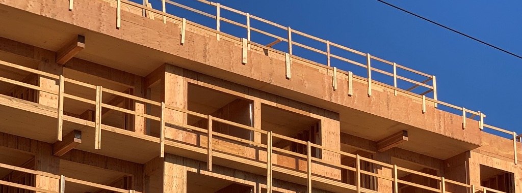
Mass Timber Floor Panel Systems for Mid-Rise ATS 2022
Mass timber floor panel systems for mid-rise light-frame wood construction are becoming more popular. Hybrid wood-framed systems have many advantages over conventional lumber floor systems such as 2×10/2×12 floor joist or I-joist systems.

FAQs Regarding Strong-Rod Anchor Tiedown Systems (ATS) for Shearwall Overturning
How would a six-story light-frame wood building perform in a large earthquake? Back in 2009, Simpson Strong-Tie was a partner in the World’s Largest Earthquake Test, a collaboration of the NEESWood project, to answer that question. This was a full-scale test which subjected the building to 180% of the Northridge earthquake ground motions (approximately a M7.5). Within the building, Simpson Strong-Tie connectors and Strong-Frame SMF were used, with the Strong-Rod™ anchor tiedown system (ATS) serving as holdown for each shearwall.
The NEESWood building was designed under Performance-Based Design methodology, and the test was conducted as validation for the approach. Buildings of similar size to the NEESWood building are built to current codes using similar products. Mid-rise light-frame wood structures continue to be a popular form of construction in various densely populated cities across the country. As part of the lateral-force-resisting system, continuous rod systems are used as the holdown for the shearwall overturning restraints. Simpson Strong-Tie has been involved with continuous rod systems since the early 2000s when we launched the Strong-Rod anchor tiedown system.
Today, rod manufacturers design the continuous rod systems with design requirements (loading, geometry, etc.) Supporting documents (e.g., installation details, layouts, RFI/markups and calculations) are submitted for each unique project. Over the years, engineers have asked many questions related to the design of these systems. In this week’s blog, we will explore Frequently Asked Questions pertaining to Strong-Rod ATS systems used as shearwall overturning restraints (holdowns).
Is there a code report for the system?
The Strong-Rod ATS system is a series of rods (fully threaded rods and proprietary Strong-Rods), coupler nuts, bearing plates, nuts and shrinkage compensation devices (ATUD/TUD and RTUD).
The majority of these components are designed in accordance with the building code and reference standards (e.g., NDS, AISC). A project-specific calculation package is submitted for each job that addresses the evaluation of these elements. Therefore, these elements are not listed in evaluation reports.
Shrinkage compensation devices, on the other hand, are proprietary components which are not addressed by the building code or reference standards. Therefore, they are tested in accordance with ICC-ES acceptance criteria AC316 and are listed in ICC-ES ESR-2320.
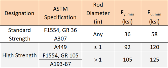
What is the material specification of the rods used above concrete?
The specified rod materials are shown in Table 1.
Can threaded rods or couplers be welded to steel beams?
Simpson Strong-Tie generally does not recommend this practice. Of the materials listed in Table 1, ASTM A307 material is the only specification that contains supplementary requirements for welding. When standard strength rod is supplied to the job, it is not guaranteed that this will be the material provided.
ASTM A449 and A193-B7 high-strength rods develop strength and ductility characteristics through controlled quenching and tempering treatments. Quenching is the rapid cooling of metal (usually by water or oil) to increase toughness and strength. This process often increases brittleness. Tempering is a controlled reheating of the metal which increases ductility after the quenching process. Precise timing in the application of temperature during the tempering process is critical to achieving a material with well-balanced mechanical properties. It is unlikely that field welding will satisfy the requirements of quenching and tempering.
Coupler nuts are generally fabricated from material exhibiting characteristics similar to high-strength rods. Thus, it is not recommended to weld coupler nuts to steel beams due to the potential for embrittlement.
Simpson Strong-Tie specifies a weldable cage which is fabricated from ASTM A36 material for such applications.
How do you calculate the Maximum ASD Tension Capacity provided in the job summary?
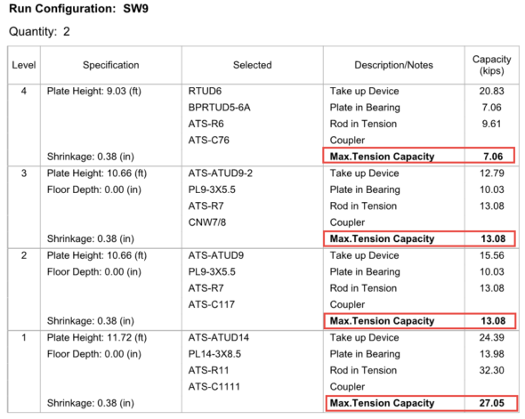
Simpson Strong-Tie provides a comprehensive design package for continuous rod systems used as holdowns for multi-story stacked shearwalls. The individual run calculations, as shown in Figure 1, provide the Maximum Tension Capacity, which correlates to the maximum force the system can deliver. Plan check often requests justification on how these values are derived at each level. These values are calculated, and the process explained below may be used on any Simpson Strong-Tie ATS Job Summary as justification.
The maximum tension capacity published within the Job Summary and the Installation Details is derived using the following procedure:
- Step 1: Evaluate the top-most level. Compare the published capacities of the rod in tension, plate in bearing and the take-up device. The lowest of these three will govern and becomes the Maximum Tension Capacity for this level.
- Step 2: Evaluate the next level down. (a) Sum the Maximum Tension Capacity from Step 1 and the published capacity of the take-up device from this level. (b) Sum the Maximum Tension Capacity from Step 1 and the published capacity of the plate in bearing from this level. (c) Compare derived values from (a) and (b) to the published capacity of rod in tension. The lowest of these three values will govern and becomes the Maximum Tension Capacity of this level.
- Step 3: Repeat Step 2 as necessary until the bottom-most level is reached.
Applying this procedure to the sample run, SW9, will wield the following result:
- Step 1: Evaluate capacities published at Level 4
- Plate in bearing (PBRTUD5-6A) = 7.06 kips governs
- Take-up device (RTUD6) = 20.83 kips
- Rod in tension (ATS-R6) = 9.61 kips
- The lowest value in Step 1 is the plate in bearing, hence 7.06 kips is the maximum load that can be delivered at Level 4 and is the Maximum Tension Capacity.
- Step 2: Evaluate capacities at Level 3
- Maximum Tension Capacity from Level 4 = 7.06 kips (See Step 1)
- Maximum Tension Capacity from Level 4 + take-up device (ATS-ATUD9-2) = 7.06 + 12.79 = 19.85 kips
- Maximum Tension Capacity from Level 4 + plate in bearing (PL9-3×5.5) = 7.06 + 10.03 = 17.09 kips
- Rod in tension (ATS-R7) = 13.08 kips governs
- The lowest value in Step 2 is the rod in tension, hence 13.08 kips is the maximum load that can be delivered at Level 3 and is the Maximum Tension Capacity.
- Step 3: Evaluate capacities at Level 2
- Maximum Tension Capacity from Level 3 = 13.08 kips (See Step 2)
- Maximum Tension Capacity from Level 3 + take-up device (ATS-ATUD9-2) = 13.08 + 15.56 = 28.64 kips
- Maximum Tension Capacity from Level 3 + plate in bearing (PL9-3×5.5) = 13.08 + 10.03 = 23.11 kips
- Rod in tension (ATS-R7) = 13.08 kips governs
- The lowest value in Step 3 is the rod in tension, hence 13.08 kips is the maximum load that can be delivered at Level 2 and is the Maximum Tension Capacity.
- Step 4: Evaluate capacities at Level 1
- Maximum Tension Capacity from Level 2 = 13.08 kips (See Step 3)
- Maximum Tension Capacity from Level 2 + take-up device (ATS-ATUD14) = 13.08 + 24.39 = 37.47 kips
- Maximum Tension Capacity from Level 2 + plate in bearing (PL14-3×8.5) = 13.08 + 13.98 = 27.05 kips governs
- Rod in tension (ATS-R11) = 32.30 kips
- The lowest value in Step 4 is due to the plate in bearing, hence 27.05 kips is the maximum load that can be delivered at Level 1 and is the Maximum Tension Capacity.
In the System Deflection Summary page(s) of the Job Summary, is the Total System Deflection provided at Allowable or Strength levels?
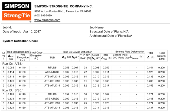
Immediately following the individual run calculations in each job summary, Simpson Strong-Tie provides a summary of deflection of the rod system similar to what is shown in Figure 2. This breaks down the deformation of all components being considered. In the example below, the rod elongation and deflection of the take-up device are summed to provide the total deflection.
The calculated system deflection is presented at ASD level. See section below for how to use these system deflections for your drift calculation.
What system deflection limit do you typically design to, and what does that include?
Unless otherwise specified on the plans or required by the building jurisdiction, Simpson Strong-Tie will design the continuous rod system to satisfy the deformation limits set forth in ICC-ES Acceptance Criteria (AC316). In some instances, the Designer may need a more restrictive deformation due to project specific conditions (e.g., tight building separations) and will require rod manufacturers to design for a lower deformation. Some jurisdictions (e.g., City of San Diego, City of San Francisco) may also have specific design requirements that continuous rod systems must conform to. The minimum recommended per-floor deformation limit set forth in AC316 is:
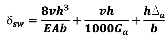
(Rod Elongation) + (Shrinkage Compensation Device Deflection) ≤ 0.2” (ASD),
Or (PDL/AE) + [ΔR + ΔA(PD/PA)] ≤ 0.2” (ASD)
Where:
PD = ASD demand cumulative tension load (kips)
L = length of the rod between restraints – i.e., floor-to-floor (in.)
A = net tensile area of the rod (in.2)
E = Young’s Modulus of Elasticity (29,000 ksi)
ΔR = seating increment of the shrinkage compensation device (as published in ICC-ES evaluation report)
ΔA = deflection of the shrinkage compensation device at the allowable load (as published in ICC-ES evaluation report)
PA = Allowable capacity (kips)
Should deformation limits be specified in the construction documents?
Simpson Strong-Tie strongly recommends this information be included in the construction documents. Along with the cumulative tension and compression forces, the required deformation limits for the holdown are important to ensure that rod manufacturers are designing the holdown to satisfy the desired shearwall performance.
How do I use the system deformation limit?
The System Deflection is the total deformation of the holdown system from floor to floor (refer to the last two columns in Figure 2). This information represents the total ASD holdown deformation term, Δa, for each level and is to be used in the shearwall drift equation from the Special Design Provisions for Wind and Seismic (2015 SDPWS 4.3-1).
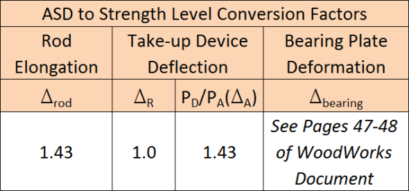
ASCE 12.8.6 requires that shearwall drift be calculated at strength level. Therefore, the information provided within the System Deflection Summary page needs to be converted from ASD to Strength Level. The conversion factors in Table 2 can be used to convert the ASD deformations to strength level. For discussions and methodology in converting bearing plate deformation to strength level, please refer to the WoodWorks Design Example of a Five-Story Wood Frame Structure over Podium Slab found here.
Can rod systems be used in Type III construction?
Yes! 2015 IBC §2303.2.5 requires that Fire Retardant-Treated Wood (FRTW) design values be adjusted based on the type of treatment used on the project. Adjustment factors vary for each FRTW manufacturer; refer to the ICC-ES evaluation report of the specified FRTW manufacturer for the unique adjustment values. Rod manufacturers need to know what treatment is being used so this information can be taken into consideration when designing compression posts and incremental bearing (bearing plates).
For more information and previous discussions on fire protection in mid-rise construction, see our previous posts: Fire Protection Considerations with Five-Story Wood-Frame Buildings Part 1 and Part 2, and Connectors and Fasteners in Fire-Retardant-Treated Wood.
What are Simpson Strong-Tie’s guidelines for fire caulking material?
While there are many options for fire-rated caulking, these products can be used in conjunction with the Simpson Strong-Tie ATS system. Below is a list of considerations when selecting and specifying a material for use where the rods penetrate the top and sole plates:
- The fire-rated caulking shall not be corrosive to metal when used in contact with ATS components.
- Direct contact with shrinkage compensating devices (e.g., TUD, ATUD, RTUD) shall be avoided. Shrinkage compensating devices have moving components and may not function properly with debris interference.
- Indirect contact with shrinkage compensating devices shall also be avoided. Shrinkage compensation accumulates up the building and therefore the largest shrinkage occurs at the top of the building. As such, when the building shrinks, remnants of the material may still be stuck to the threads of the rod and may be detrimental to the performance of some shrinkage compensating devices (e.g., an RTUD). It is recommended to detail the installation with shrinkage taken into consideration.
- The fire-rated caulking should be pliable to accommodate wood shrinkage and the building moving down during this process.
- The performance and the suitability of fire-rated caulking are outside the scope of Simpson Strong-Tie.
Why doesn’t your design include compression post design?
If the Engineer of Record has already specified compression posts to be used with a continuous rod system, Simpson Strong-Tie will not provide these on the holdown installation drawings. This is primarily done to prevent discrepancies between the specification in the contract documents and what is shown on the installation drawings.
What is the maximum spacing between compression posts?
For platform-framed structures, the maximum spacing between compression posts is 9″. The large majority of Simpson Strong-Tie bearing plates will fit within the 9″ spacing requirement, eliminating the need for notching compression posts. In some framing conditions, such as balloon framing or a top chord bearing truss, the maximum spacing will be reduced to 6″. This is due to the limited amount of space between the top of the compression posts transferring uplift (via bearing) into the point of restraint (e.g., bearing plate) at the level above. To ensure this load path is complete, the posts need to be spaced closer.
What is the nailing schedule for the bridge block to the king studs?
Simpson Strong-Tie doesn’t recommend nailing the bridge block to the cripple as the bridge block member will shrink. Locking the bridge block in place may result in a gap forming between the bottom of the bridge block member and the top of the cripple studs, which is not accounted for in the Total System Deflection.
Are there any published documents with design examples of continuous rod systems used in mid-rise construction?
There are two resources publicly available that provide discussion and examples. The first is a manual published by the Structural Engineers Association of California (SEAOC). Titled 2015 IBC SEAOC Structural/Seismic Design Manual Volume 2 – Examples for Light-Frame, Tilt-Up and Masonry Buildings, this document provides two examples – one for a four-story wood hotel building, and the other for a three-story cold-formed steel apartment building on concrete podium deck.
Another useful resource is published by WoodWorks and is a design example of a five-story wood-frame structure over podium slab. This document can be found here.
What questions do you have about the Strong-Rod ATS System? Leave them below.
How to Select a Connector Series – Holdowns
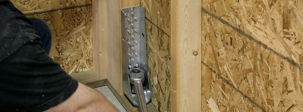
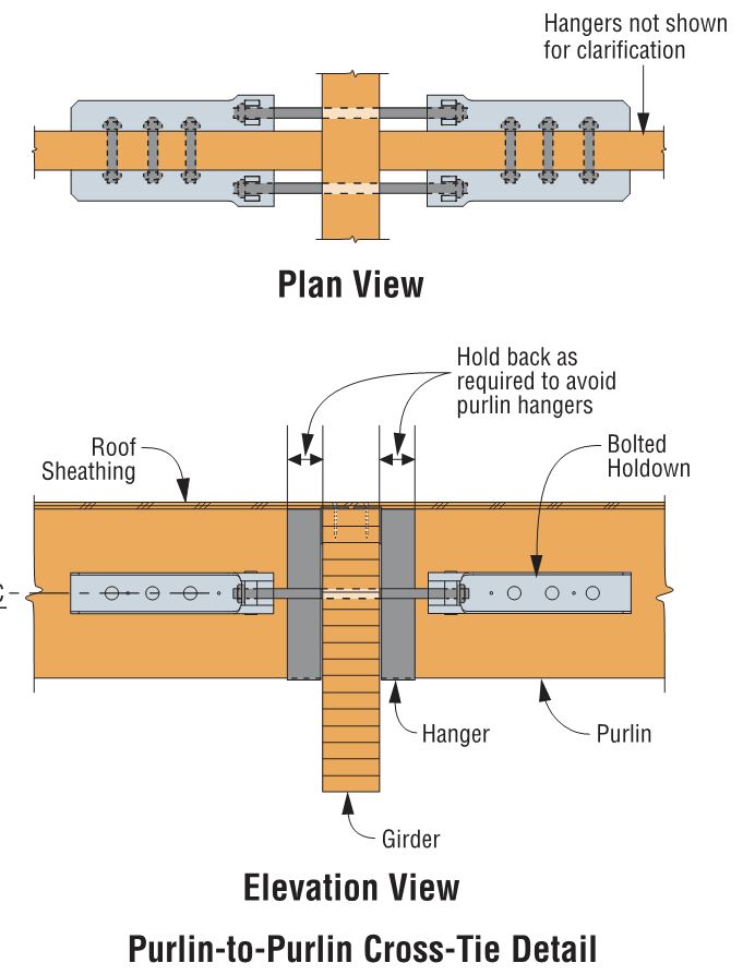
Keith Cullum started off our “How to Select a Connector” series with Hurricane Ties. This week we will discuss how to select holdowns and tension ties, which are key components in a continuous load path. They are used to resist uplift due to shearwall overturning or wind uplift forces in light-frame construction. In panelized roof construction, holdowns are used to anchor concrete or masonry walls to the roof framing.
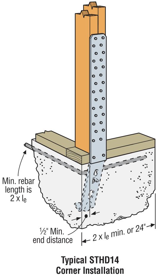
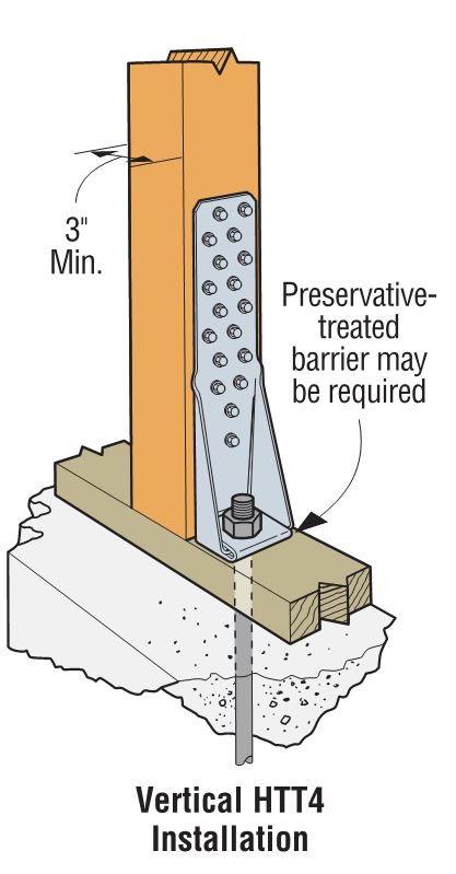
Holdowns can be separated in two basic categories – post-installed and cast-in-place. Cast-in-place holdowns like the STHD holdowns or PA purlin anchors are straps that are installed at the time of concrete placement. They are attached with nails to wood framing or with screws to CFS framing. After the concrete has been placed, post-installed holdowns are attached to anchor bolts at the time of wall framing. The attachment to wood framing depends on the type of holdowns selected, with different models using nails, Simpson Strong-Tie® Strong-Drive® SDS Heavy-Duty Connector screws or bolts.
A third type of overturning restraint is our anchor tiedown system (ATS), which is common in multistory construction with large uplift forces. I discussed the system in this blog post.
 Given the variety of different holdown types, a common question is, how do you choose one?
For prescriptive designs, such as the IRC portal frame method, the IRC or IBC may require a cast-in-place strap-style holdown. Randy Shackelford did a great write-up on the PFH method in this post.
For engineered designs, a review of the design loads may eliminate some options and help narrow down the selection.
| Holdown Type | Maximum Load (lb.) |
| Cast-in-Place | 5,300 |
| Nailed | 5,090 |
| SDS Screws | 17,685 |
| Bolted | 19,070 |

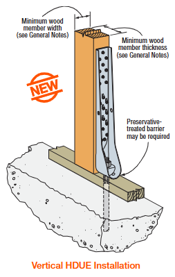
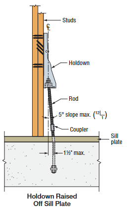
Adjustability should be considered when choosing between a cast-in-place and a post-installed holdown. Embedded strap holdowns are economical uplift solutions, but they must be located accurately to align with the wood framing. If the anchor bolt is located incorrectly for a post-installed holdown, raising the holdown up the post can solve many problems. And anchors can be epoxied in place for missing anchor bolts.
 We are often asked if you can double the load if you install holdowns on both sides of the post or beam. The answer is yes, and this is addressed in our holdown general notes.
Nailed or screwed holdowns need to be installed such that the fasteners do not interfere with each other. Bolted holdowns do not need to be offset for double-sided applications. Regardless of fastener type, the capacity of the anchorage and the post or beam must be evaluated for the design load.
Once you have selected a holdown for your design, it is critical to select the correct anchor for the demand loads. Luckily, I wrote a blog about Holdown Anchorage Solutions last year. What connector would you like to see covered next in our series? Let us know in the comments below.

Taking Wood-Framed Construction to New Heights
When I had more hair and less of it was gray, I worked on a project as an assistant engineer doing the calculations for a mixed-use building in San Jose, California. Final design consisted of four stories of wood framing over a concrete podium slab and another level of below-grade parking. At that time, my firm had designed many two- and three-story residential buildings, but common thinking was you switched to steel or concrete for taller structures because of perceived limitations in wood-framed construction.Continue Reading