2015 IRC Adds New Options for Deck Construction

Early this summer a package arrived at my office that I knew right away was either a copy of a new building code or design standard. Some codes or standards are more exciting than others to open up and see what’s new and different. As it turns out, this package was the just-published 2015 International Residential Code (IRC). With my interest in wood decks, I have to admit that this was new information that I was happy to see.

Why? Similar to my blog post in May mentioning the limited design resources currently available to engineers, the IRC itself is also a work in progress when it comes to the prescriptive details included for decks. Performance requirements for the framing and guards has always been included in Chapter 3, but it wasn’t until the 2009 and 2012 editions that prescriptive information for attaching a deck ledger to a wood band joist with lag screws or bolts, and a detail for transferring lateral loads to a support structure, were included. Key improvements for the 2015 IRC include provisions for composite materials, clarification of the prescriptive ledger information, and prescriptive information for decking, joist and beam allowable spans, post heights and foundations.

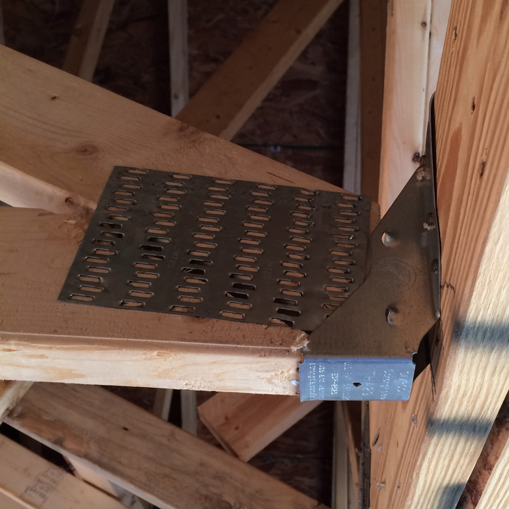
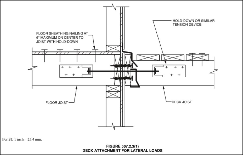
Lateral load connections at the support structure were a significant topic during the development of the 2015 IRC. The permitted method already in the code involves constructing the Figure 507.2.3(1) detail with 1,500 pound hold-downs, in two or more locations per deck. The detail transfers the lateral load by bypassing the joist hanger and ledger connections, and ultimately transfers it into the floor diaphragm of the support structure. The concentrated nailing on the floor joist and the need to have access from below to the install the hold-down can cause undesirable complications for builders with existing conditions. A number of common conditions also differ significantly from the detail, such as the floor joists running parallel to the deck ledger and alternate floor joist types, including i-joists or trusses. In response to frequently-asked-questions from the industry, our technical bulletin T-DECKLATLOAD provides commentary to consider for these situations. The technical bulletin also offers an alternate floor joist-to-sheathing connection that may save the builder from removing a finished floor in an existing condition or from adding additional sheathing nailing from above.

2015 International Residential Code
Figure: 2015 International Residential Code; International Code Council

In order to provide greater flexibility, a second option is now included in the 2015 IRC: constructing Figure R507.2.3(2) with 750 pound hold-downs in four locations per deck. This detail also transfers the lateral load in bypassing the joist hanger and ledger connections, but transfers the load to the wall plates, studs, or wall header by means of a screw anchoring the hold-down. In some cases, builders will hope this detail can save removing interior portions of an existing structure, but close attention will be required in terms of the deck joist elevation with respect to components of the wall and ensuring that hold-down anchor has proper penetration into the wall framing.

Figure: 2015 International Residential Code; International Code Council

There are still a number of scenarios where a residential deck builder may need or want to consider hiring a structural engineer. Prescriptive details for guards and stairs are still not included in the code, as well as lateral considerations such as the deck diaphragm or the stability of a freestanding deck. Alternate loading conditions, such as the future presence of a hot tub, are also outside the scope of the current code. The allowance for alternative means and methods permitted by Chapter 3 of the 2015 IRC, is also something to keep in mind when the prescriptive options do not fit well with the project conditions. For example, the IRC ledger fastening table applies for connections to a band joist only and not to wall studs or other members of the adjacent support structure.

Have you been involved with any residential deck projects?  Let us know in the comments section below.

Introducing the Joist Hanger Selector Web App

Designing buildings and dealing with construction has always been a satisfying career for me. It is challenging to design a complete structural system, coordinate with the other consultants and create a clear set of construction documents for the contractor. Throughout my career, I’ve occasionally had a few panicked “Uh oh!” moments. I hope I’m not alone in admitting those happen. These typically occur far away from work when something prompts me to think about a project. I might see concrete being placed, then question whether I remembered to change the reinforcing callout on a mat slab I had just designed. I can’t stop thinking about it until I get back in the office to check.

I had an “Uh oh!” moment a few days after I started work at Simpson Strong-Tie. We have a training plan I call Catalog 101 where new engineers meet with each engineer who is an expert for a given product line. After I had met with our experts on holdowns, concrete anchors and engineered wood products, it was on to top-flange hangers (and my “Uh oh!” moment).

Catalog 101
We really do call it Catalog 101

After learning a lot of things I didn’t know about hangers, we moved on to available options for some of our top-flange hangers – sloped, skewed, sloped and skewed, sloped top-flange, and offset top-flange. I learned that some hanger options get full load, some have small reductions and others large reductions. For example, the GLT with an offset top-flange gets 50% of the table load.

GLT/HGLT hanger options section of Wood Construction Connectors Catalog, C-2013

“Uh oh!”

I had recently designed a project and specified a bunch of GLT hangers with offset top-flanges. I hadn’t noticed there was a reduction for this modification; I just thought it was really cool that Simpson Strong-Tie had a hanger that worked at the end of a beam. Minor panic set in until I could check my calculations. Fortunately, the beams at the framing conditions that required offset hangers had half the load of the typical beams, so the hanger was okay even with the load reduction.

Hanger Option Matrix from Wood Construction Connectors Catalog, C-2013

The Wood Construction Connectors Catalog has a Hanger Options Matrix that makes it relatively simple to see which options – sloped, skewed, concealed, welded – are available for each hanger. The pages following the options matrix have more detailed information about size restrictions and load reductions associated with each option. It can be somewhat tedious to sift through all of the options and apply the reduction factors, so I always recommend using the Simpson Strong-Tie Connector Selector® software to do the work for you.

Connector Selector
Connector Selector

Connector Selector software allows you to input you geometry and loads and returns a list of connectors that meet those requirements, including any reductions due to modifications. Connector Selector is a desktop application, which needs to be downloaded and installed on your PC. Engineers have indicated they like the functionality of Connector Selector, but wished the input was more intuitive and preferred it as a web application.

Joist Hanger Selector web app

I’m happy to say we listen, and the new Simpson Strong-Tie Joist Hanger Selector web app is available now. The easy-to-use interface enables users to quickly select the connection details and print out results. You can access the app from any web browser without having to download or install special software. The allowable loads are automatically calculated to reflect reductions associated with modifications – no more “Uh oh!” moments for me (at least with hangers).

Joist Hanger Selector App
The joist hanger selector app makes it easy to pick the right hanger.

Give the new Joist Hanger Selector web app a try and let us know what you think. We always appreciate your feedback!

Snow Loads vs. Top Chord Live Loads – A Historical Look at Snow Loading for Trusses

In my former life working as a consulting engineer, I reviewed many truss submittal packages. I remember during my reviews wondering how it was possible to get so much information on to an 8½ inch by 11 inch piece of paper. I also remember how a lot of what was being reported was difficult to understand without some help interpreting the information. 

As many of you may know, Simpson Strong-Tie has ventured into the truss industry and we are now offering truss connector plates and software to component manufacturers around the country. So given my past experiences, I figure some of you might appreciate some insight into the engineering that goes on behind those truss submittal packages. So I have asked one of our great truss engineers, Kelly Sias, to put together some blog posts on the topic that we can share our knowledge with you. Kelly has worked in the truss industry for years and spent time as the Technical Director at the Truss Plate Institute. I am sure her blog posts are going to help all of us have a better appreciation for trusses.

Have you ever been involved in a discussion with someone on a project that ended with “but that’s the way we’ve always done it!”? I heard those words spoken by a contractor in my first engineering job when I tried explaining why his single stud would not work at a particular location. When he said something about his grandfather having always done it that way, I knew I could explain the calculations all day and it wouldn’t do much good.Continue Reading

Minding the Gap in Hangers

Mind The Gap sign
Mind The Gap sign

Have you ever seen this famous sign? You may have seen it while riding the London Underground, to draw attention to the gap between the rail station platform and the train door. The warning phrase is so popular that you may also recognize it from souvenir T-shirts or coffee mugs.

In the connector world, the phrase comes to mind when thinking of the space, or “gap” between the end of the carried member and the face of the carrying member. Industry standards for testing require that a 1/8” gap be present when constructing the test setup (in order to prohibit testing with no gap, where friction between members could contribute significantly), so this is the gap size that is typically permitted for the joist hangers listed in our catalog.

Gaps exceeding 1/8” can affect hanger performance in several ways. A larger gap creates more rotation for the connector to resist by moving the downward force further from the header. Fasteners may also have reduced or no penetration into the carried member due to the gap. Testing confirms that these factors decrease hanger allowable loads for larger gaps.

Hanger installation with gap
Example of field installation with a 1” gap (approx.)

What are my options then if the field conditions create a gap larger than 1/8”? We have performed testing to establish allowable loads for many common joist and truss hangers with gaps up to 3/8” (up to ½” for HTU hangers), as well as testing for possible field remedies and repair scenarios. Our technical bulletin T-C-HANGERGAP18 provides this information, along with a design example, and general recommendations and guidelines for preventing gaps. Notes on shim details are also included – shim size, material, and attachment (independent of the hanger fasteners) are key design considerations that must be covered by the engineer or truss designer.

What is your experience dealing with hangers that exceed 1/8” gaps? Let us know in the comments below.

Use of Holdowns During Shearwall Assembly

When designing a shearwall according to the International Building Code (IBC), a holdown connector is used to resist the overturning moment due to lateral loading.  From a structural statics point of view, a shearwall without dead load or holdowns would have zero lateral-resisting capacity without any restraint to resist the overturning moment. Since the wall assembly still has the sill plate anchorage providing resistance to overturning, testing can measure the capacity of a wall assembly without holdowns.

Continue Reading

Plated Wood Truss Hip End Styles

For many, the first day of summer means it is time to cinch up your favorite hip-hugging bathing suit and enjoy the warm weather. For the truss industry, it’s time to keep those hip-hugging bathing suits in the closet and take advantage of the favorable weather months by bidding and building as many jobs as possible. During the bid and build frenzy, there will be several hip end jobs leaving truss yards across the country, but what exactly is a hip end and what are the different styles?

Truss hip ends drawing
Roof with Multiple Hip Ends (blue), Plan View

The Structural Building Components Association website (SBCA) defines a hip roof as a “Roof system in which the slope of the roof at the end walls of the building is perpendicular to the slope of the roof along the sides of the building.” While framing terms differ by region, most trussed hip end systems will include hip trusses, jack trusses (end and side) and a rafter or corner girder truss. Hip end style and setback (distance from side or end walls to the hip girder truss) may also vary by building design and region.

In the western part of the country, a California Hip system is typically seen in many trussed structures. In this hip system, the hip truss flat top chord is dropped by the plumb cut of the jack top chord at the roof pitch. By doing this, the top chords of the end jack trusses can pass over and bear on the dropped flat top chords. As the height of the hip end roof plane increases, the height of the flat top chord also increases, though the interval at which the flat top chord height increases may vary by building design and region.

Truss Design: California Hip System
California Hip System, Plan View
Truss Design: California Hip Rendering
California Hip System, Rendering

East of the Rocky Mountains, the California Hip is rare and a Step-Down Hip system is more popular. Differing from the California Hip, a Step-Down Hip system is one where every truss under the hip end plane decreases in height, or “steps down” from the apex until it reaches the hip girder, which is placed at a pre-determined setback.

Step Down Hip System, Plan View
Step Down Hip System, Rendering

Less regional and more situational depending on the building design, are the Lay-In Gable, Dutch and Terminal Hip systems. The Lay-In Gable Hip system is one with many regional names and shares similarities with the California and Step Hip systems. Like the Step Hip, every truss steps down moving from the apex to the setback. Like the California, every truss flat top chord has a drop. However, the flat top chord is dropped by the plumb cut of a 1.5” member at the roof pitch, as the gable frame lays flat.

Roof System: Lay-In Gable Hip System, Plan View
Lay-In Gable Hip System, Plan View (Gable Frame shown in green for clarity)


Lay-In Gable Hip System, Rendering

In a Dutch Hip system, the hip end roof plane does not converge with the side planes to form an apex. Instead, the hip end plane pitches directly into the girder truss that is placed at a predetermined setback. Jack trusses then connect to the hip girder truss or to a ledger attached to the hip girder truss.  This hip system is also referred to as a Dutch Gable.

Dutch Hip System, Plan View
Dutch Hip System, Rendering

Assuming like roof pitches and heel heights, a Terminal Hip system is one where the hip girder truss setback is half of the main truss span or building width. If pitches and heel heights vary, the girder truss is placed at the apex of the three converging roof planes, which could be more or less than half of the main truss span or building width.

Terminal Hip System, Plan View
Terminal Hip System, Plan Rendering
Terminal Hip System, Plan Rendering 

While these are some common hip end styles in the truss industry, there are definitely others. Each style has its own advantages and disadvantages, and a discussion of those will be the topic of a future post.

What other types of hip end styles are you familiar with? Let us know in the comment section below.

Resources and Continuing Education for Structural Engineers

I’ll admit that I’m biased, but structural engineers have the best job in the world. We’re needed to create safe sound structures while factoring in the effects of environmental forces using a combination of physics and experience. It takes a really well rounded individual to do all of that.

In my opinion, the key to being a well rounded professional is to never stop learning or seeking out new resources in your industry. I thought I’d share with you some resources that may be helpful to you as a structural engineer, from my own experience:

Continuing Education Webinars

Attending webinars online is a great way to get Continuing Education credits you need. Webinars enable you to stay sharp on topics that are continually changing and that you may need to adapt to in our industry.

Some of the resources engineers at Simpson Strong-Tie go to for webinars and CECs include:

ACI – American Concrete Institute

AISC – American Institute of Steel Construction

ASCE – American Society of Civil Engineers

AWC – American Wood Council

CFSEI – Cold-Formed Steel Engineers Institute

NCSEA –  National Council of Structural Engineers Association

SEAOSC – Structural Engineers Association of Southern California  

Engineering Associations

Training
Structural engineering associations often offer in person trainings.


Keeping in touch with fellow structural engineers means that you can talk shop and get some great advice about issues you face on the job. Some associations you can look into:

SEAINT- Structural Engineers Association – International 

NCSEA- National Council of Structural Engineers Associations 

SEAOC- Structural Engineers Association of California

SEAOSC- Structural Engineers Association of Southern California 

SEAOCC- Structural Engineers Association of Central California 

SEAOSD- Structural Engineers Association of San Diego

SEAU- Structural Engineers Association of Utah

ASCE- American Society Of Civil Engineers

ACI- American Concrete Institute

AISC- American Institute of Steel Construction

PCA- Portland Cement Association

PCI- Precast/Prestressed Concrete Institute

CRSI- Concrete Reinforcing Steel Institute

AISI- American Iron and Steel Institute

Simpson Strong-Tie also offers great software resources for structural engineers and other building industry professionals. What resources do you recommend? Let us know in the comments below.

New Holdown Requirements for the IRC® and IBC® Portal Frame Bracing Method

The IRC® contains several different narrow bracing methods that are made up of portal frames. One method that is useful if you are using intermittent wall bracing is the Method PFH Portal Frame with Holdowns. This method relies on low-deflection holdown anchorage at the bottom, and substantial nailing at the overlap of the sheathing and the header at the top to prevent overturning of the narrow panel. An identical method for use as wall bracing is in the Conventional Construction section in Chapter 23 of the IBC®. These portal frames were first included in the 2006 IBC and IRC.

Method PFH- Portal Fram With Holdowns

The method was originally tested with straps clamped to a steel test bed to simulate the embedded holdown straps. The straps were nailed to the wood with enough nails to mimic a 4,200 lb. strap anchor. The original test report is APA T2002-70. At that time, the Simpson Strong-Tie® STHD14 had a published allowable load in excess of 4,200 lbs. based on then-current Acceptance Criteria, so hardware was available to construct this frame throughout the country. However, in 2008, ICC Evaluation Service developed a new acceptance criteria for embedded connectors, AC398, Acceptance Criteria for Cast-in-place Cold-formed Steel Connectors in Concrete for Light-frame Construction. This was in response to the changes in ACI 318 for anchors in concrete. When re-tested and evaluated using the new Acceptance Criteria, the allowable load for STHD14 was reduced below 4,200 lbs. for use in buildings designed for Seismic Design Categories C through F.   The same thing happened to other manufacturers’ embedded holdown allowable loads. That made it impossible to properly construct this bracing method in those areas. In response to this, Simpson Strong-Tie worked with APA, the Engineered Wood Association, to design a new test that would determine if a lower capacity holdown could be used with this portal frame method.  APA performed the testing at their Tacoma, Washington testing lab. Since the initial testing of the portal frames with the 4,200 lb. holdown was performed using the outdated SEAOSC protocol with an older testing rig that used a stiff beam above the wall, both the old tests with a simulated 4,200 lb. holdown and new tests with a simulated 3,500 lb. holdown were rerun in accordance with the current ASTM E2126 test method using the CUREe protocol. The test was published as Test Report T2012L-24. The tests showed little to no effect of reducing the holdown from 4,200 lbs. to 3,500 lbs. allowable load. Here is one of the graphs of the backbone curves comparing the two assemblies for a 16-inch wide, 10-foot tall portal frame.

Comparison graph of two assemblies for a 16-inch wide, 10-foot tall portal frame.

With the testing complete, APA prepared and submitted code changes to both the 2012 International Building Code® and 2012 International Residential Code®. The IBC proposal is S291-12, and can be found on page 605 of the 2012 Proposed Changes to the International Building Code – Structural. The IRC proposal is RB311-13, and can be found on page 613 of the 2013 Proposed Changes to the International Residential Code-Building. With support from Simpson Strong-Tie, both of the proposals were approved. So in the 2015 IRC, bracing method PFH will require an embedded strap-type holdown with a minimum capacity of 3,500 lbs. instead of 4,200 lbs. The same will hold true for the Alternate Braced Wall Panel Adjacent to a Door or Window Opening bracing method in the 2015 IBC. APA also re-tested the portal frames with only two sill plates instead of three. This will allow the use of a 5/8” by 8” Titen HD® anchor as a retrofit anchor bolt. What are your thoughts? Let us know in the comments below.

Plated Wood Truss Design Responsibilities

When the opportunity presents itself, glance up at the ceiling. Do you ever wonder who the responsible parties were for the design and construction of the roof above? If you’re involved in the truss industry, there is no doubt you have. If not, it never hurts to be in the know. Since we spend a significant portion of our life under a roof, it helps to know a few facts about what’s over our heads.

Truss drawing
Truss drawing

Roofs built from prefabricated wood trusses used in light-frame and residential construction will be the focus of this blog post.

The current national design standard for metal plate connected wood truss construction is ANSI/TPI 1-2007, which is the referenced standard in the 2009 and 2012 IBC and IRC. So what are design responsibilities for wood trusses and why are they important? They are a series of responsibilities required by key parties for applications of trusses in the construction of a building. These key parties (Owner, Building Designer, Registered Design Professional, etc.) are important because each is required to produce pertinent information about the truss and truss system from its inception to erection and long in-service life.

Plan
Plan
Rendering of Trusses

As wood trusses have evolved, so have publications about their construction, quality and use.  The first standard was published in 1960, with subsequent standards published periodically.

In 1995, the Truss Plate Institute (TPI) published ANSI/TPI 1-1995, which served as the first ANSI consensus-based national design standard for metal-plate connected wood truss construction. One of many new chapters established in ANSI/TPI 1-1995 was chapter 2, identifying design responsibilities. While early versions of ANSI/TPI 1 introduced design responsibilities, chapter 2 of ANSI/TPI -2007 has clarified and added areas of responsibility that are vital for today’s component industry. In addition, the 2007 edition defined responsibilities regarding temporary and permanent restraint and bracing, and special inspection requirements to long span trusses (any truss with a span of 60 feet or greater). These are just a few, yet critical additions to the standard.

Without clear definitions of responsibility, how would the industry know who specifies truss connections, or who provides bracing locations necessary to a roof assembly and its duration of service? Additionally, who determines if a project requires a truss submittal package, or the type of information it must provide? While these questions and more are answered in ANSI/TPI 1-2007, any provisions of the TPI 1 Design Responsibilities can be changed in the contract documents for a given project, so long as all parties are made aware of and agree to the revisions.

Ensuring all parties’ know and follow the design standard can help ensure a properly designed, manufactured and erected truss that will lead to a safe roof system. If you’re a component manufacturer, knowing what you’re responsible for and required to produce can get you out of a jam or better yet, help you avoid one altogether. Communication is key to the industry. The Commentary and Appendices of ANSI/TPI 1-2007 is available for web review: http://www.tpinst.org/technical-downloads

ANSI TPI 1
ANSI TPI 1

Do you know or want to know the answers to the above questions? Or perhaps think there are responsibilities that need to be clarified or added to future publications of ANSI/TPI 1? Let us know in the comment section below.