


Designing my first building was truly a learning experience. I remember one event in particular when I determined the required thickness for a steel column base plate. That day I wrote “1.5-inch thk. min.” on my calc pad and months later while out walking the job, I got to see that 1.5-inch thick plate in the flesh. Let me tell you, it was much thicker and heavier in-person than on my calc pad. This eye-opening experience – the realization that what you’re designing isn’t just a word or a number, but rather a physical object with width, height, length and weight – is something every structural engineer goes through early in their career. Designing something on paper doesn’t convey those physical properties very well.Continue Reading

Simpson Strong-Tie Structural Engineering/Architecture Student Scholarship Program
Let’s be honest, going to school and majoring in structural engineering or architecture is not easy. Just look at Paul McEntee’s post about his experience with his semester long course in Statics at 7:00 AM complete with Friday pop quizzes for proof in our post about Statics and Testing. While these majors may be a challenge, we know that the degree at the end is well worth the effort. Our industry is a great one to work in and not only do we make other people’s lives better, but we also can save lives too. Which is exactly why Simpson Strong-Tie has developed a structural engineering/architecture scholarship program. Continue Reading

Midrise of Steel

The number of midrise structures constructed using light-frame cold-formed steel (CFS) certainly seems to be increasing each year. As with any material, there are benefits and challenges, especially in areas of moderate to high seismic risk. This post will discuss these as well as potential solutions.
Light-frame CFS midrise construction often uses ledger floor framing primarily to facilitate the load transfer detailing at the floor, tension anchorage (tie-downs or hold-downs) and compression chord studs or posts designed to resist the amplified seismic overturning loads. CFS framing is typically thin and singly symmetric.

Amplified Seismic Load
The AISI Lateral Design standard (AISI S213-07/S1-09) Section C5.1.2 requires that the nominal strength of uplift (tension) anchorage and the compression chord studs for shear walls resist the lesser of (1) the amplified seismic load or (2) the maximum load the system can deliver when the response modification coefficient, R, greater than 3. The amplified seismic load is defined as the load determined using the ASCE 7 seismic load combinations with the overstrength factor, Wo, which may be taken as 2.5 for CFS framed shear wall systems with flexible diaphragms.
Typically, the maximum the system can deliver to the uplift anchorage or chord studs is taken as the forces determined using the nominal shear strength of the shear wall assembly tabulated in the seismic shear wall table in S213 multiplied by 1.3. The S213 commentary accounts for the tabulated loads being based on Sequential Phased Displacement (SPD) rather than CUREE cyclic protocol and the degraded backbone curve. See the Structure magazine article that discusses the design of CFS framed lateral force-resisting systems.
Continuous Rod Tie-Down Systems
Light-framed CFS over three stories often use continuous rod tie-down systems rather than cold-formed steel hold-downs to resist shear wall overturning forces as they offer increased load capacity. Neglecting the dead load contribution, the amplified seismic load requirement for CFS shear walls using an R greater than 3 results in an 80% increase in the load used to size the continuous rod tie-down system compared to design level loads. For shear walls using an R greater than 3, it is important to note on the design drawings whether the uplift loads shown are ASD, LRFD, amplified ASD or amplified LRFD so the appropriate tie-down system may be designed.
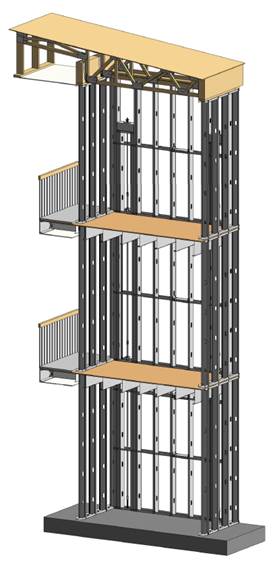
Continuous rod tie-down systems are designed not only for strength, but also checked to ensure they do not deflect too much to cause the top of shear wall drift to exceed the code limit or to exceed the 0.20” vertical story deflection limit required by some jurisdictions and ICC-ES AC316. Take-up devices are used in CFS framed structures to take-up construction and settlement gaps that may occur. AISI S200 Section C3.4.4 states that a gap of up to 1/8” might occur between the end of wall framing and the track. The vertical elongation of the continuous rod tie-down system includes rod elongation (PL/AE) and the take-up device deflection due to the seating increment and the deflection under load.
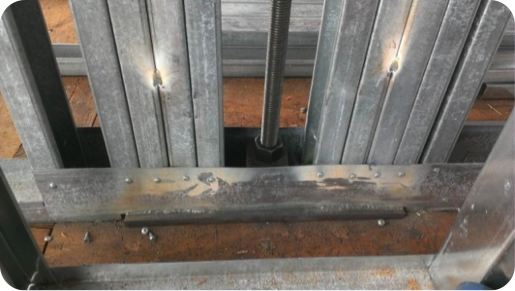
In addition, coordination is important in using continuous rod tie-down systems in CFS structures because the walls are often prefabricated offsite. An example is the consideration of the appropriate detail for the steel bearing plate installed at the floor sheathing in the story above to resist the uplift (tension) force from the story below.
One possible detail is to install the bearing plate in the bottom CFS track under all the CFS chord studs, but it’s important to ensure the bottom track flanges are deep enough to screw them to the stud flanges as the bearing plate can have a thickness of 1 ½” or more and typical tracks use 1 ¼” flanges. It is also important to ensure that the bearing plate width fits in the track. Another possible detail is to install the bearing plate under the CFS track under all the CFS chord studs. However, then it must be cut into the floor sheathing and may cause the bottom track to be raised at the bearing plate. For this detail, the floor shear transfer must be detailed through the ledger into the CFS framing.
Concrete Tension Anchorage
The concrete tension anchorage is designed according to ACI 318 Appendix D using the continuous steel rod material and size in accordance with S213 to have the nominal strength to resist the lesser of the amplified seismic force or the maximum load the system can deliver. ACI 318-11 Section D.3.3.4.3 offers four force limits for design of concrete tension anchorage design in Seismic Design Category C through F:
(1) The concrete nominal tension anchorage strength shall be greater than 1.2 times the ductile steel rod nominal tension anchorage strength
(2) The anchorage design strength shall be greater than the maximum tension force that can be delivered by a yielding attachment;
(3) The anchorage design strength shall be greater than the maximum tension force that can be delivered by a non-yielding attachment; and
(4) The anchorage design strength shall be greater than the amplified seismic force.
Typically either option (1) or (4) is used where (1) would lead to less concrete required than (4) if the bolt is efficiently sized while (4) would be required for such conditions as a vertical irregularity. See the concrete anchorage and podium anchorage SE Blog posts for more details.

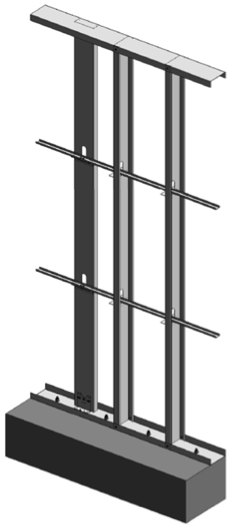
CFS Wall Stud Bracing
CFS studs are typically thin and singly symmetric and thus require bracing. AISI S211 (Wall Stud Design Standard) permits two types of bracing design that cannot be combined; sheathing based or steel based. There are limits on the stud axial strength when using sheathing braced design. It’s important to identify on the drawings that the sheathing braces the studs and another load combination must be used for the stud design.
2012 IBC Section 2211.4 requires stud bracing to be designed using either AISI S100 (North American Specification) or S211 (Wall Stud Design Standard). S100-07 Section D3.3 required nominal brace strength is to be 1% of the stud’s nominal compressive axial strength, but S100-12 Section D3.3 changes this to the required brace strength is to be 1% of the stud’s required compressive axial strength (demand load). In addition, D3.3 requires a certain stiffness for each brace. AISI S211 required brace strength is to be 2% of each stud’s required compressive axial strength for axially loaded studs and, for combined bending and axial loads, be designed for the combined brace force per S100 Section D3.2.2 and 2% of the stud’s required compressive axial strength.
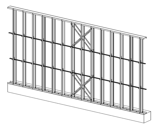
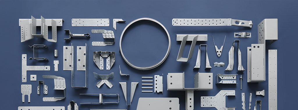
There are two primary types of steel stud bracing systems: bridging and strap bracing. U-channel bridging extends through the stud punchouts and is attached to the stud with a clip, of which there are various solutions such as this post on Wall Stud Bridging. Bridging bracing requires coordination with the building elements in the stud bay. It installs on one side of the wall, and does not bump out the wall sheathing. It also requires periodic anchorage to distribute the cumulative bracing loads to the structure for axially loaded studs often using strongback studs and does not require periodic anchorage for laterally loaded studs since the system is in equilibrium as the torsion in the stud is resisted by the U-channel bending.
Flat strap bracing is installed on either side of the wall and at locations other than the stud punchout. It bumps out the sheathing and requires periodic anchorage to distribute the cumulative bracing loads to the structure for axially and laterally loaded studs.
![]()

![]()
Light-frame cold-formed steel construction has been used successfully for many projects, but there are challenges that must be addressed to ensure code compliance and desired performance. Some beneficial resources for designing CFS structures are the SEAOC 2012 IBC Structural/Seismic Design Manual Volumes 1 and 2 and the Cold-Formed Steel Engineers Institute’s (CFSEI) website where you can find technical notes and design guides.
What have been some of your observations or challenges in designing cold-formed steel midrise structures?

Podium Anchorage – Structure Magazine
It is hard to believe it has been almost two years since I posted The Anchorage to Concrete Challenge – How Do You Meet It? That post gave a summary of the challenges engineers face when designing anchorage to concrete. Challenges include just doing the calculations (software helps), developing a high enough load, satisfying ductility requirements or designing for overstrength. Over the past several years, Simpson Strong-Tie has worked closely with the Structural Engineers Association of Northern California (SEAONC) to help create more workable concrete anchorage solutions for light-frame construction.

This month’s issue of Structure magazine has an article, Testing Tension-Only Steel Anchor Rods Embedded in Reinforced Concrete Slabs, which provides an update on the ongoing work of SEAONC and Simpson Strong-Tie. The goal of the testing program is to create a useful design methodology that will allow structural engineers to develop the full tensile capacity of high-strength anchor rods in relatively thin (10” to 14”) podium slabs.
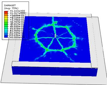
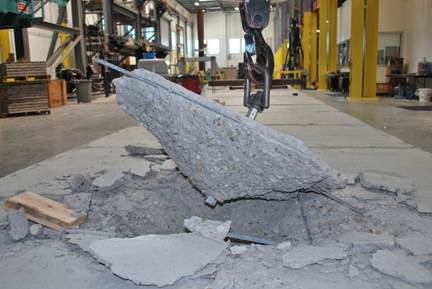
Anchor capacity is limited by steel strength, concrete strength, embedment depth, and edge distances. One way to achieve higher anchor strengths is to design anchor reinforcement per ACI 318-19 Chapter 17.
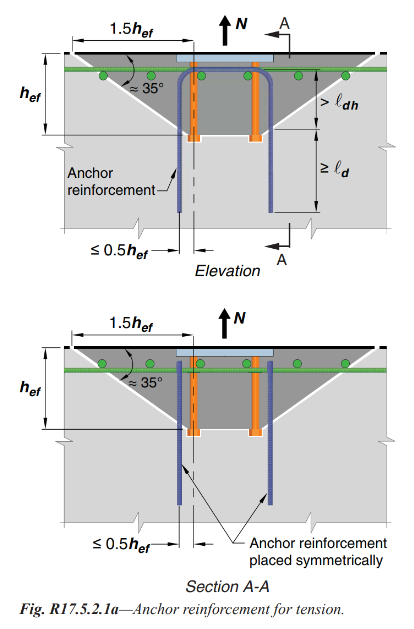
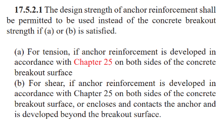
Section 17.5.2.1 requires anchor reinforcing to be developed on both sides of the breakout surface. Since this is not practical in thin podium slabs, alternate details using inclined reinforcing perpendicular to the breakout plane were developed and tested.
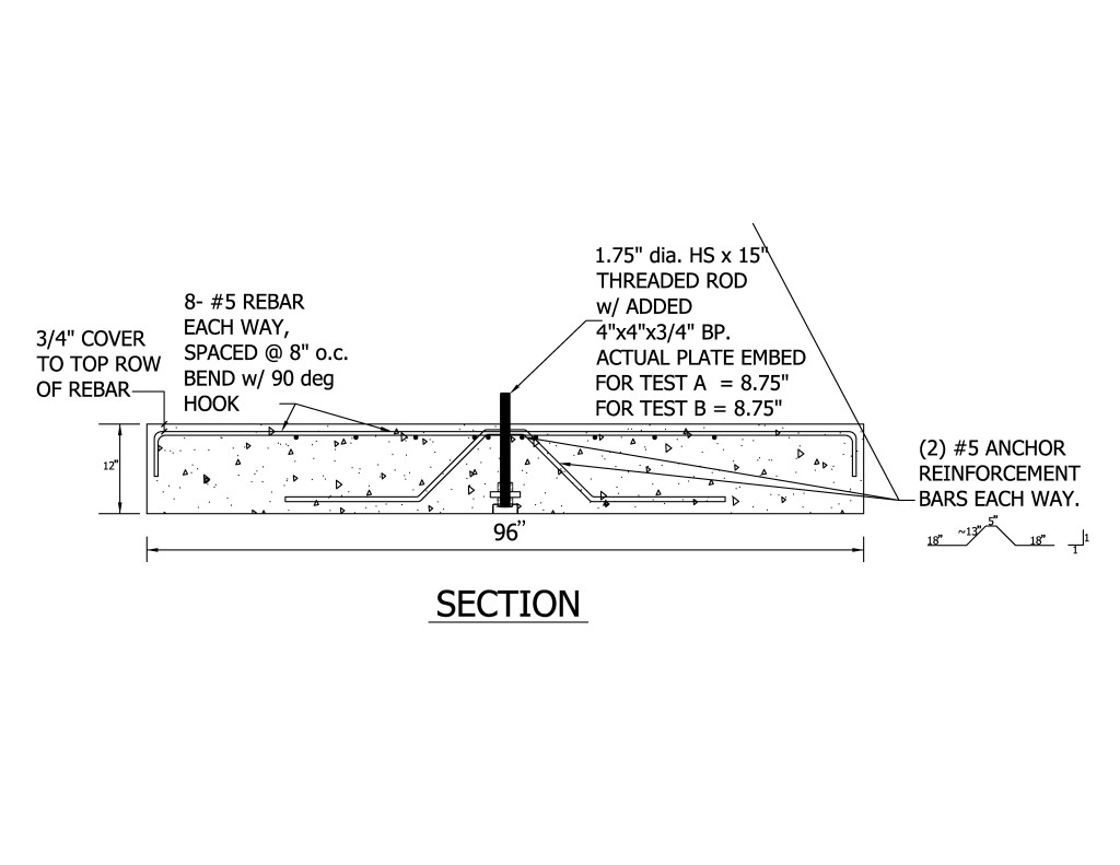
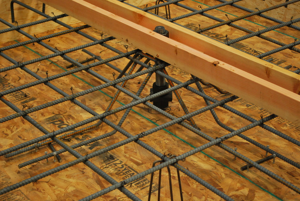
This month’s Structure magazine article summarizes the test results for anchors located at the interior of the slab, away from edges. Additional testing is needed for anchor solutions at the edge of slab. The anchor reinforcement concepts are similar, yet additional detailing is required to prevent side-face blowout failure modes. This testing is in progress at the Tyrell Gilb Research Laboratory and will be completed later this year.
Did you read the Structure article? What are your thoughts?

Meet Our Genuine Connector Campaign Grand Prize Winners
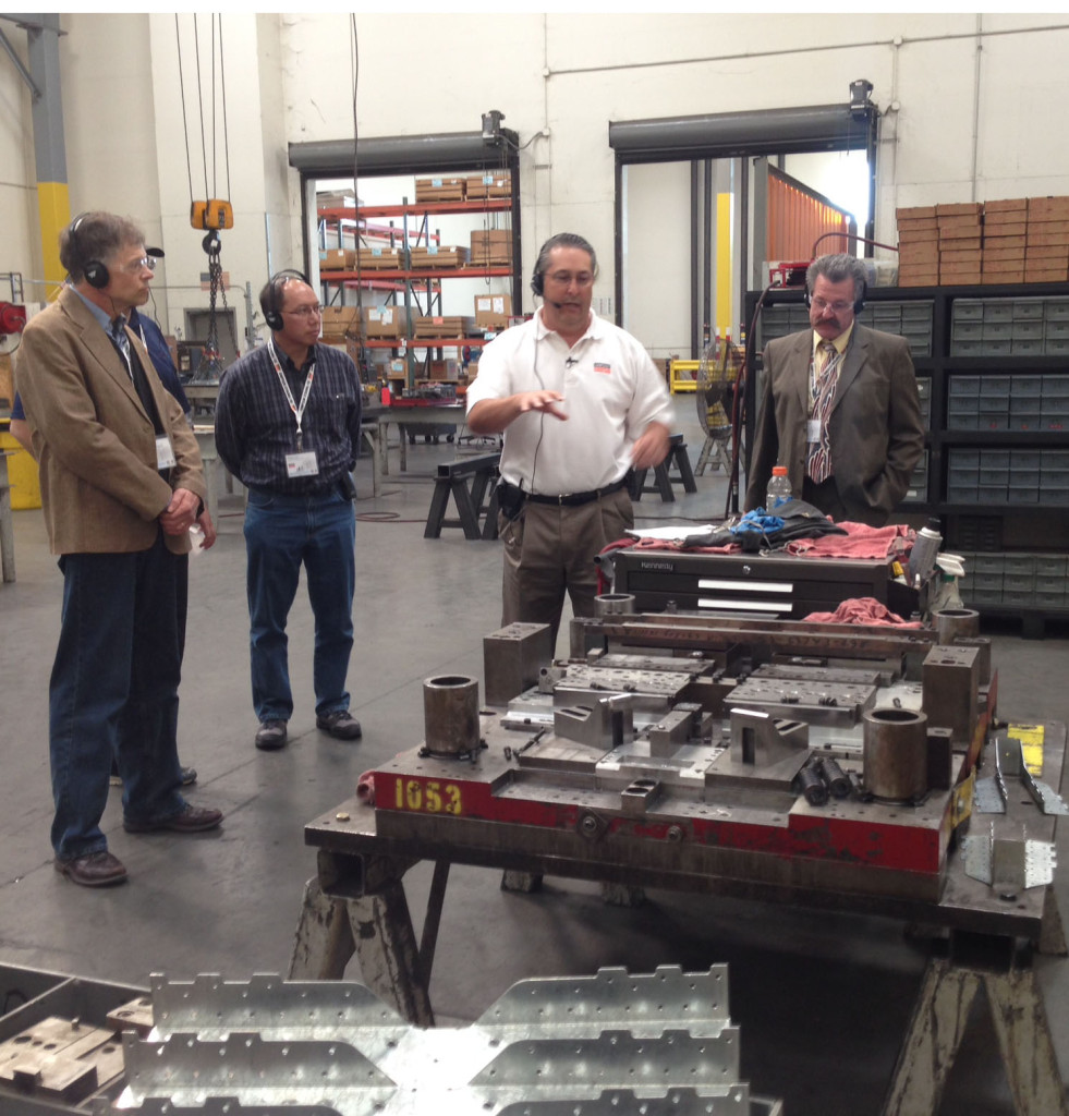
As part of our Genuine Connector Campaign, we had the pleasure of meeting with customers who won our Genuine Simpson Strong-Tie® Connectors contest. The grand prize was an all-expense paid trip to the San Francisco Bay area, and the opportunity to tour our state-of-the-art lab facilities as well as meet our senior managers. There were six winners; four visited us last October and we’re looking forward to meeting two more next month.
We launched a contest last year inviting customers to tell us their Genuine story. I shared mine in this blog post last January. As I mentioned in my previous post, our founder Barclay Simpson, made his very first connector for a customer in 1956. Barc believed in doing whatever it took to help the customer succeed. Today, helping the customer remains our number one priority. Whether that’s being on a jobsite to help with a product installation, making office calls to conduct product training or spending endless hours on R&D and product testing. This is what we promise to do everyday, and we do it genuinely.
But we wanted to know what it means to you. So we asked the question, “Why do you choose Genuine Simpson Strong-Tie® Connectors?”
We received many thoughtful, amazing responses. Honestly, it was hard to choose just six to receive our grand prize! Here are our the winning entries:
“It would be very easy for me to say that Simpson Strong-Tie Connectors are the only brand available in my area, which is true, but given a choice I would always select Simpson Strong-Tie. There are several reasons why I will always purchase Simpson Strong-Tie. First, I am quite impressed by Simpson Strong-Tie research and development to improve existing products and produce new ones. I have been fascinated by the extensive research facilities depicted in online videos. Especially, a video of the four- or five-story structure on the shake table for earthquakes. Your level of R&D tells me Simpson Strong-Tie backs everything they sell. Secondly, the quality of the products is impressive. The products are clean, without sharp edges or burrs from manufacturing processes, consistent in size and fit. Third, I appreciate the Simpson Strong-Tie commitment to meeting and exceeding building codes and keeping me up-to-date with specific applications. Lastly, I am impressed with Simpson Strong-Tie as a company: its people, leadership in its field and commitment to the building industry. Simpson Strong-Tie does not just talk about it. Simpson Strong-Tie does it.” P. Austin, North Adams, MA
“Think about what the world would be like without Genuine Simpson Strong-Tie® Connectors. In the Midwest, where recent storms have ravaged many communities, the losses would have been exponentially worse. The design and construction industries rely on this product line to make design and construction simpler using Simpson Strong-Tie. We take it for granted, I’m glad Simpson Strong-Tie doesn’t.” P. Lum, Florissant, MO
“Whether it is coated, stainless or composite, Simpson Strong-Tie is my connection. None of our projects are simple. Our strength, ingenuity and commitment require us to use the best of everything. Using Simpson Strong-Tie products means “never having to say you’re sorry.” The range of your products offer solutions to the many challenges we face. Many thanks to Barclay and his people for creating a company I can count on. It’s just that simple. I look forward to meeting your team someday. Many thanks, and keep up the good work!” T. Gould, Ashaway, RI
“My customers are looking for quality and innovation that they can count on. For years we have experienced that quality with Simpson Strong-Tie and continue to reap the benefits of products that save time and money and perform above expectations. The ability for Simpson Strong-Tie to build and ship custom products is second to none and often just what is needed to solve unexpected issues during the framing stage of our customers’ projects. Simpson Strong-Tie seems to always be ahead of code changes and working to help our customers with compliance. There is no equal!” L. Holmes, Torrington, WY
“The reason I use Simpson Strong-Tie is that they have the BEST customer service of any vendor that I have ever used. ANYONE that you get on the phone has the answer NOW on pricing, availability and any technical questions. The shipments are ALWAYS on time and in my 15 years, I have never seen a mistake. I deal with a lot of vendors and no one holds a candle to the service that Simpson Strong-Tie provides.” M. Stroupe, West Hartford, CT
“I have four reasons why I choose Genuine Simpson Strong-Tie Connectors. You can see them here in this picture. From left to right, they are Lilah, Callie, Hollie (being held), and Seth. Their safety is worth specifying connectors I can trust.” P. Giessel, Eagle River, AK
The contest may be over, but we’re still interested in your answer to the question: “Why do you choose Genuine Simpson Strong-Tie® Connectors?”
Narrow Face Installations
Engineered wood products have been used in wood-framed construction for many decades. Early forms of engineered wood include plywood as replacement for 1x wood sheathing and glu-laminated beams that could be fabricated in larger sizes with optimized material utilization. I-joists utilizing deep plywood webs and solid sawn lumber flanges solved the challenge of longer floor spans. Oriented strand board (OSB) eventually replaced plywood in the webs, while the innovation of laminated veneer lumber (LVL) became common in the flange material.
In addition to I-joists, structural composite lumber is widely used as a replacement for solid lumber. This could be for a number of reasons such as availability of longer lengths, straighter sections and higher strengths. Structural composite lumber (SCL) may be LVL, parallel strand lumber (PSL), laminated strand lumber (LSL) or oriented strand board (OSB).
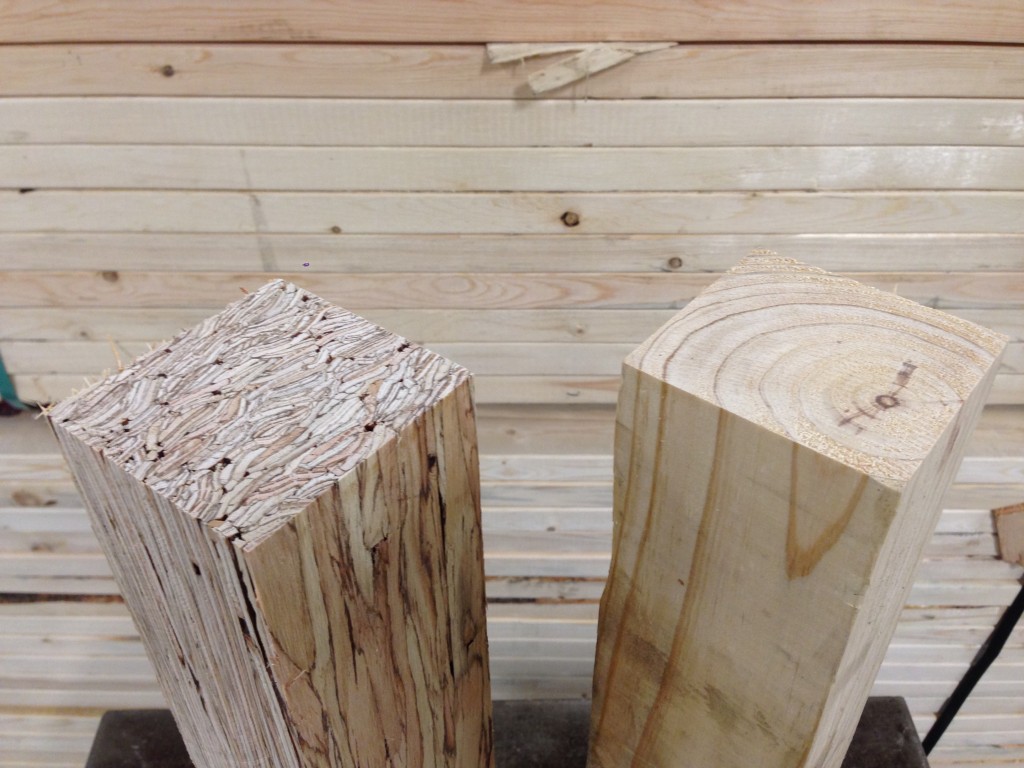
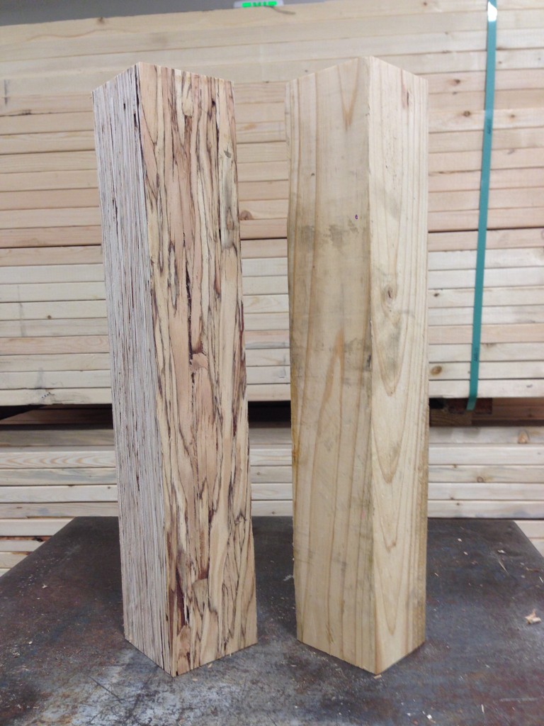
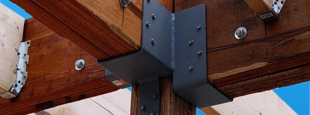
Structural composite lumber has two faces. If the cross-section is rectangular, say 3½x5¼, the narrow face will show the edges of the SCL layers. In a square section, the face that shows the SCL layers is still referred to as the narrow face. Fasteners will have lower performance when they are installed in the narrow face of SCL. While this is not an issue for beams, Simpson Strong-Tie connectors such as post bases, column caps or holdowns may have reduced allowable loads when installed on the narrow face of SCL columns.
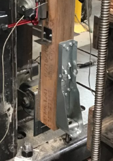
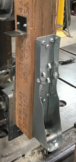

To support the use of Simpson Strong-Tie connectors installed on SCL post material, we have run many tests over the years. The reductions are published in the technical bulletins, T-C-SCLCLM25 (U.S. version) and T-C-SCLCLMCAN25. The reduction factors range from 0.45 to 1.0, and vary based on SCL material type – LSL, PSL, or LVL – and also by connector and fastener type.
It is important to understand the magnitude of the reductions. While narrow face installations may be unavoidable, engineers will need to specify the correct lumber and hardware combination to meet the design loads.
Share additional thoughts by leaving a comment.
Genuine Connector Collection Art
In this earlier post, I shared the story of my brother-in-law indicating that he thought some of the connectors specified on a swim club project were “ugly.” The contractor and I were able to come up with some other options, but I guess I’m still upset with my brother-in-law for calling Simpson Strong-Tie® connectors ugly. I’ll have to walk into his office sometime and comment on the attractiveness of his financial audits. How pretty are those nonrecurring charges, unrealized capital gains and special purpose entities?Continue Reading

Engineering Fees

[Simpson Strong-Tie note: Shane Vilasineekul is the Simpson Strong-Tie Engineering Manager for the Northeast U.S. and one of our guest bloggers for the Structural Engineering Blog. For more on Shane, see his bio here.]
Are you finding it difficult to keep your fees competitive?
“Codes are becoming more complex.”
“Builders are demanding lower construction costs.”
“If I don’t allow this they will find an engineer who will.”
“Competition is stiffer.”
“New proprietary systems take too long to evaluate.”
“We have less time to do our job”
“Architects don’t give us enough to work with.”
“Other engineers are not doing it right.”
Working at Simpson Strong-Tie for 15 years, I have had the opportunity to speak with thousands of engineers and these are recurring themes. Some of these issues are way above my pay grade, but there may be something each of us can do to help keep our profession healthy.
A few years ago we had Susan Dowty from the California offices of S.K. Gosh speak at our SEA of Ohio conference. After her presentation, she stuck around to hear Steven Regoli from the Ohio Board of Building Standards. The gist of his presentation was that Ohio building officials don’t have the authority to reject sealed plans or even require calculations to be submitted unless there is clear evidence of a code violation. Midway through, a very lively discussion broke out between Susan and Steven about the responsibilities of plans examiners as they relate to structural design. On one side you have plans examiners who are licensed engineers and perform something akin to a peer review, and on the other side you have plans examiners with little engineering background that rely on the licensed engineer to ensure structural provisions are met. With some exceptions, the first view is held by many western states and the latter by many states in the South, Midwest and East Coast.

So how does this affect engineering fees? Well, when all it takes to collect a fee is a sealed set of structural plans, the temptation is there to cut corners in the design process and, in an increasingly competitive market, provide clients with a building that costs less to construct than one properly designed. I take pride in working in a profession that holds ethics in such high regard, but it only takes a few to give in and disrupt the market in a particular region. It seems like these “few” are gaining in numbers the last several years. Without proper checks and balances, this trend could continue.
So what can we do about it? I don’t think local government would be open to increasing the payroll for building departments to hire more engineers to review plans (building departments in Ohio saw some of the first and most severe cuts during the recent recession), but maybe we can help raise the bar for structural plan review. Steven Schaefer, the founder of Schaefer structural engineers in Cincinnati, decided years ago to take it upon himself to educate Ohio building departments on the fundamentals of structural engineering. He regularly presents at their meetings and has even created a guide to help plan reviewers look for proper load paths and lateral force-resisting systems. Next week he will be presenting four courses at their state conference and will be honored with an award for all his efforts over the years. We may not all be able to have the same impact, but most of us could spare a few hours each year to work with our local engineering association to reach out to building departments and offer training and support.
Leave a comment if you have some ideas on how to maintain our high standards, or better yet, share some successes you have seen in your area.

Social Media Tips for Structural Engineers
In January, our engineer Shane Vilasineekul wrote about his top ten mobile apps. Today we’re talking social media and how it can help you be better at your job. Now I know that the common notion of social media is that it is more of a place to goof off from work, but stay with me here. Think of social media as a place where people can meet. There is a big difference between bars versus a conference for professionals. While they are both places where people can meet in one spot, they perform different functions. Social media is the same way. It can be used for non-professional networking, but it can also be a helpful place where structural engineers can learn about new products, industry news and trends.
Here are ways that structural engineers can use social media:
Use Twitter for Industry Events and Trends: Twitter’s strongest point is its brevity. With a 140-character limit, tweets can really get to the point. Another reason that Twitter is useful is that it is often the social media platform where you see things unfold in real time. For example, you can search industry specific events and see tweets in live time and learn about the demonstrations and seminars your colleagues think are useful, the ones to skip, etc.
LinkedIn Is An Industry News Resource: LinkedIn is not just a place to show off your resume any more. LinkedIn is becoming a hub for industry news. Do you want to know what is going on with other structural engineers? You can join industry specific groups to share tips and ideas. It’s also good practice to follow companies and clients that you work with so you know when they launch a new product, promote a new project or even share their own social media content.
Subscribe to Blogs: Following structural engineering blogs like this one ensures that you never miss a beat about what other industry folks are saying. Subscribing to a blog post means that you can read all the content an industry blog has to offer all from the comfort of your inbox. Blogs also can cover day-of/breaking news that you can’t get from trade publications.
Facebook For Recommendations: While you may look at Facebook as a more family and friends zone, there is something to be said for interacting with fellow structural engineers on this platform. If you are friends with former classmates, you will find a bevy of articles that are helpful for you from an industry standpoint. You can also ask industry specific questions to your friends or ask for recommendations from people you know and trust. Following company pages opens up opportunities to give ideas for new products, learn new product uses, or even find out about new promotions and offers.
YouTube For Educational Videos: An educational video can be a lot more effective and useful than reading a paper. Seeing how a company does product testing may even take the guesswork from your own job. At Simpson Strong-Tie, we make videos for our YouTube channel so you can see our products in action whether it’s a test or even a DIY project.
I hope this blog post takes the guesswork out of social media for you. While these are some starter suggestions, the sky is the limit. What do you use social media for? Do you see professional benefits? Let us know in the comments section.

Educated in a FLASH, Part 2
This week’s blog was written by Branch Engineer Randy Shackelford, P.E., who has been an engineer for the Simpson Strong-Tie Southeast Region since 1994. He is an active member of several influential committees, including the AISI Committee on Framing Standards, the American Wood Council Wood Design Standards Committee, and the Federal Alliance for Safe Homes Technical Advisory Committee. He is vice-president and member of the Board of Directors of the National Storm Shelter Association. Randy has been a guest speaker at numerous outside seminars and workshops as a connector and high wind expert. Here is Randy’s post:
In my last blog post, I gave an overview of FLASH, the Federal Alliance for Safe Homes, and how Simpson Strong-Tie partners with them. Last November, FLASH held their Annual Conference. The theme of this past meeting was “15 Years of Stronger Homes and Safer Families,” and it was one of their best conferences yet.Continue Reading