“Change is the only constant in life” and “When you are finished changing, you are finished” are quotes from the ancient Greek philosopher Heraclitus and Benjamin Franklin, respectively. I’m reminded of them as I review the numerous changes to codes and standards during the typical three to five-year development cycles. While code and standard changes can be challenging to incorporate into our work, they typically offer an improvement or expansion of design and construction solutions.
Tag: CFS
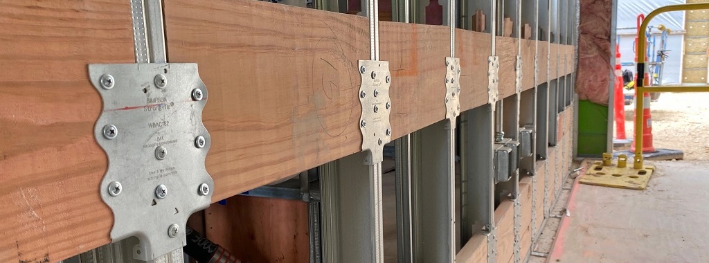
Introducing a Tested Connector (WBAC) to Support Wood Backing in Cold-Formed Steel Walls
Engineers spend much of their career designing and detailing main structural members which are exposed to significant structural loads. An experienced engineer will often master this type of design and excel at detailing an efficient building system. However, these same savvy engineers are sometimes left scratching their heads when tasked with providing a clean and simple design for attaching components such as cabinets, shelves or handrails to interior finish. Simpson Strong-Tie’s versatile new WBAC Wood Backing Steel Connector provides the engineer with a fully tested design solution that efficiently and easily attaches wood backing members for heavy wall hangings.
CFS Designer™ v2.5 Makes Cold-Formed Steel Design Easier Than Ever
With the use of engineering software tools, structural engineers can design buildings faster and more efficiently than ever before. In this blog post, Clifton Melcher, P.E., a senior project manager for cold-formed steel connectors, discusses the various enhancements included in version 2.5 of Simpson Strong-Tie® CFS Designer™ software.
Continue Reading
The Cold-Formed Steel Construction Catalog is HOT off the press!
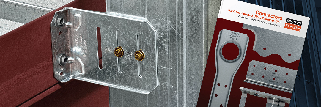
The SE Blog is taking some time off for the 4th of July holiday this week. However, we’ve just released the 2017 edition of our Connectors for Cold-Formed Steel Construction catalog – order a hard copy to be mailed to your office or download a PDF copy and start using it today!
Connectors For Cold-Formed Steel Construction
The C-CF-2017 is a 308-page catalog including specifications, load tables and installation illustrations for our cold-formed steel connectors and clips, helping you easily specify and install in commercial curtain-wall, mid-rise and residential construction.
DoD-Compliant CFS Wall Framing Design
Back in the year 2000, the U.S. Department of Defense (DoD) was charged with incorporating antiterrorism protective features into the planning, design and execution of its facilities. The main document developed to meet this requirement is the Unified Facilities Criteria “DoD Minimum Antiterrorism Standards for Buildings” (UFC 4-010-01). The current version was published in October 2013. This document covers what is most commonly referred to as “blast” design.Continue Reading
BRACE FOR IMPACT! Bracing Design for Cold-Formed Steel Studs
While consideration of bracing is important for any structural element, this is especially true for thin, singly symmetric cold-formed steel (CFS) framing members such as wall studs. Without proper consideration of bracing, excessive buckling or even failure could occur. Bracing is required to resist buckling due to axial or out-of-plane lateral loads or a combination of the two.
There are two methods for bracing CFS studs as prescribed by the American Iron and Steel Institute (AISI) Committee on Framing Standards (COFS) S211 “North American Standard for Cold-Formed Steel Framing – Wall Stud Design” Section B1. One is sheathing braced design and the other is steel braced design.
Sheathing braced design has limitations, but it is a cost effective method of bracing studs since sheathing is typically attached to wall studs. This design method is based on an assumption that the sheathing connections to the stud are the bracing points and so it’s limited by the strength of the sheathing fastener to stud connection. Due to this limitation, the Designer has to use a steel braced design for most practical situations. AISI S211 prescribes a maximum nominal stud axial load for gypsum board sheathing with fasteners spaced no more than 12 inches on center. AISI S211 Section B1 and the Commentary discuss the design method and assumptions and demonstrate how to determine the sheathing bracing strength.
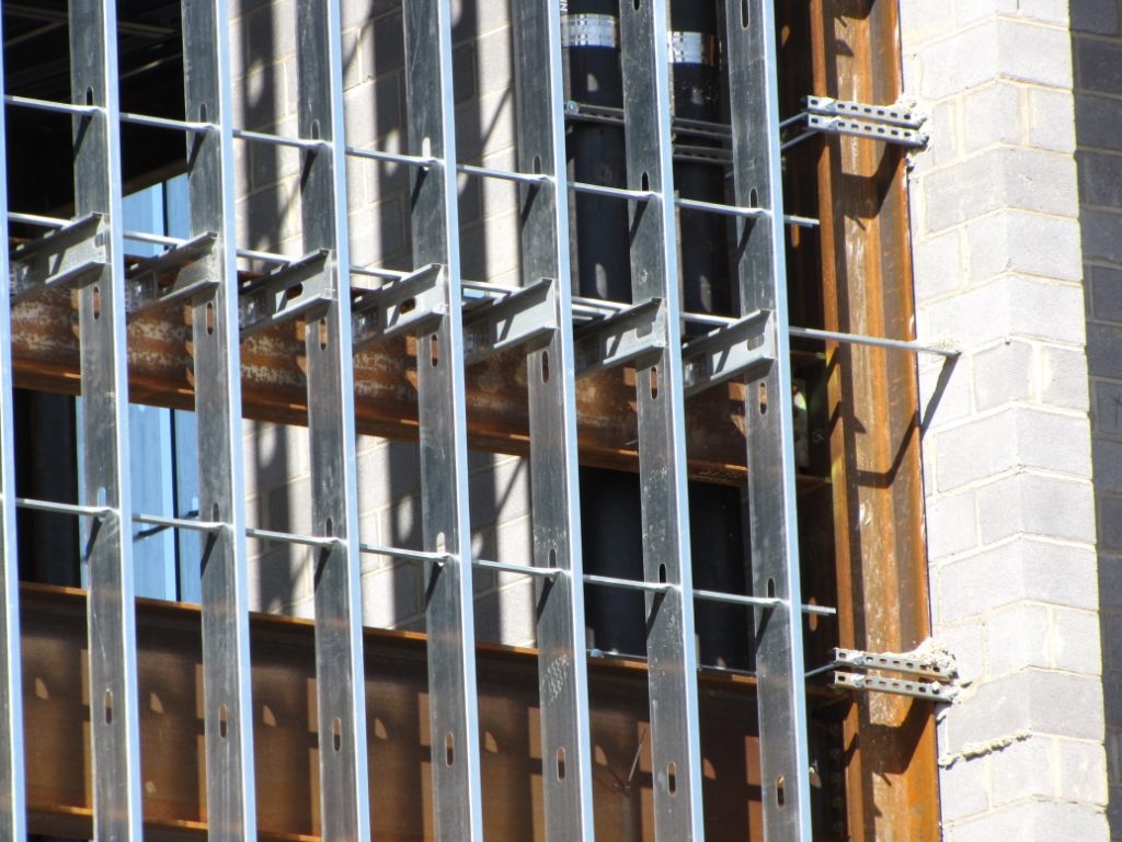
Sheathing braced design requires that identical sheathing is used on each side of the wall stud, except the new AISI S240 standard Section B1.2.2.3 clarifies that for curtain wall studs it is permissible to have sheathing on one side and discrete bracing for the other flange not spaced further than 8 feet on center. The wall stud is connected to the top and bottom tracks or supporting members to provide lateral and torsional support and the construction drawings should note that the sheathing is a structural element. When the sheathing on either side is not identical, the Designer must assume the weaker of the two sheathings is attached to each side. In addition, the Designer is required to design the wall studs without the sheathing for the load combination 1.2D + (0.5L or 0.2S) + 0.2W as a consideration for construction loads of removed or ineffective sheathing. The Designer should neglect the rotational restraint of the sheathing when determining the wall stud flexural strength and is limited by the AISI S100 Section C5.1 interaction equations for designing a wall stud under combined axial and flexural loading.
Steel braced design may use the design methodology shown in AISI S211 or in AISI Committee on Specifications (COS) S100 “North American Specification for the Design of Cold-Formed Steel Structural Members.”

Steel braced design is typically either non-proprietary or proprietary “clip and bridging” bracing, or “flat strap and blocking” bracing periodically spaced along the height of the wall stud.
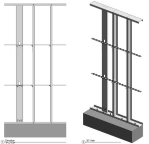
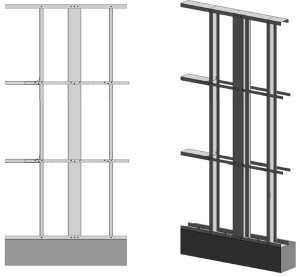
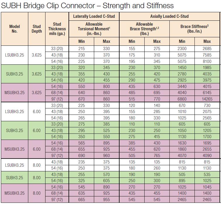
Proprietary wall bracing and wall stud design solutions can expedite design with load and stiffness tables and software as well as offer efficient, tested and code-listed solutions such as Simpson Strong-Tie wall stud bridging connectors.
Steel braced design is a more practical bracing method for several reasons. First, during construction, wall studs go unsheathed for many months, but are subjected to significant construction loads.This is especially true for load-bearing, mid-rise structures. Second, some sheathing products, including gypsum wallboard, can be easily damaged and rendered ineffective if subjected to water or moisture. Third, much higher bracing loads can be achieved using mechanical bracing. IBC Section 2211.4 permits Designers to design steel bracing for axially loaded studs using AISI S100 or S211. However, S100-07 requires the brace to be designed to resist not only 1% of the stud nominal axial compressive strength (S100-12 changes this to 1% of the required compressive axial strength), but also requires a certain brace stiffness. S211 requires the Designer to design the bracing for 2% of the stud design compression force, and it does not have a stiffness requirement. . AISI S100 is silent regarding combined loading, but S211 provides guidance. S211 requires that, for combined loading, the Designer designs for the combined brace force determined using S100 Section D3.2.1 for the flexural load in the stud and either S100 or S211 for the axial load. In addition, the bracing force for stud bracing is accumulative as stated by S211 Commentary section B3. As a result, the periodic anchorage of the bracing to the structure such as strongbacks or diagonal strap bracing is required.
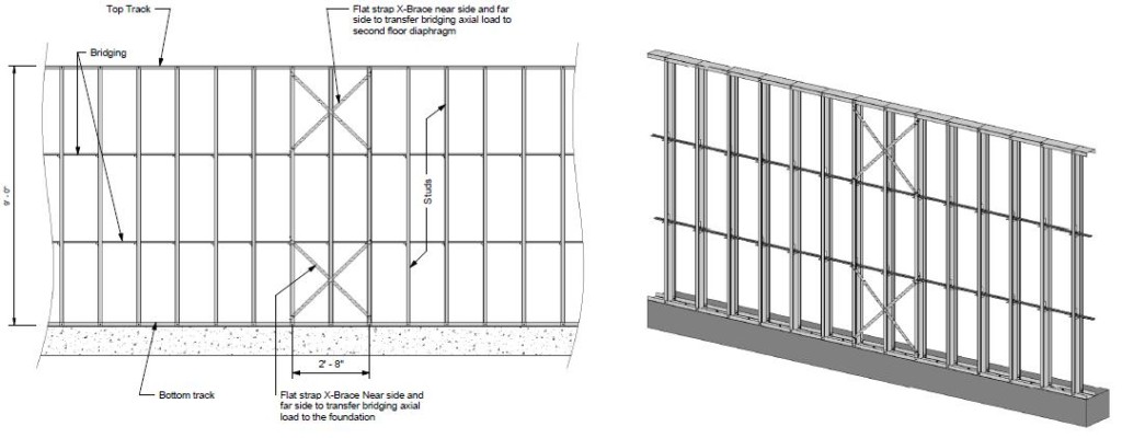
Some benefits and challenges of steel clip and bridging bracing include:
- Proprietary solutions, such as the Simpson Strong-Tie SUBH bridging connector, can significantly reduce installed cost since many situations require only one screw at each connection.
- Unlike strap bracing, u-channel bracing can be installed from one side of the wall.
- U-channel bracing does not create build-up that can make drywall finishing more difficult.
- Extra coordination may be required to ensure that u-channel bridging does not interfere with plumbing and electrical services that run vertically in the stud bay.
- Bracing for axial loaded studs requires periodic anchorage to the structure, such as using strongbacks or diagonal strap bracing.
- Bracing of laterally loaded studs does not require periodic anchorage since the system is in equilibrium as torsion in the stud is resisted by bridging (e.g., U-channel) bending.
Some benefits and challenges of steel flat strap and blocking bracing include:
- May be installed at other locations than stud punchout.
- Required to be installed on both sides of wall.
- Bumps out sheathing.
- Bracing for axial loaded studs requires periodic anchorage to structure, such as using strongbacks or diagonal strap bracing (same load direction in stud flanges).
- Bracing for laterally loaded studs requires design of periodic blocking or periodic anchorage to the structure (opposite load direction in stud flanges).
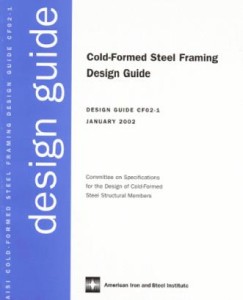
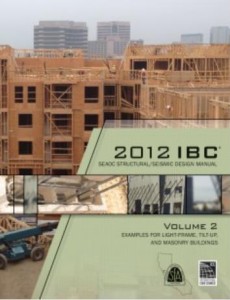
There are several good examples Designers may reference when designing CFS wall stud bracing. They include AISI D110 Cold-Formed Steel Framing Design Guide that may be purchased from www.cfsei.org, SEAOC Structural/Seismic Design Manual Volume 2 Example 3 that may be purchased from www.seaoc.org, and the Simpson Strong-Tie wall stud steel bracing design example on page 60 of the C-CFS-15 CFS catalog.
Cold-formed steel framing is a versatile construction material, but Designers need to carefully consider the bracing requirements of the AISI specification and wall stud design standard. What cold-formed steel wall bracing challenges have you encountered and what were your solutions?
Call for Papers: 22nd International Conference on CFS Structures

The Wei-Wen Yu Center for Cold-Formed Steel Structures has issued a Call for Papers for the 22nd International Conference on Cold-Formed Steel (CFS) Structures, to be held Nov. 5-6 in St. Louis, MO. The goal of the conference is to enable sharing of state-of-the-art information pertaining to CFS design.
Both engineering researchers and practitioners have provided valuable contributions to the conference. Past proceedings are available online.
 Researchers and practitioners are encouraged to submit abstracts for consideration by the conference steering committee. Application-oriented topics highlighting innovations in CFS applications are strongly encouraged. The deadline is Dec. 31. Abstracts may be submitted by e-mail to ccfss@mst.edu.
What are your thoughts? Visit the blog and leave a comment!
23rd Short Course on CFS Structures: October 15-17 in St. Louis
Simpson Strong-Tie is sponsoring the 23rd Short Course on Cold-Formed Steel Structures hosted by the Wei-Wen Yu Center for Cold-Formed Steel Structures (CCFSS). The course will be held on October 15-17, 2013 at the Drury Plaza Hotel at the Arch in St. Louis, MO.
This course is for engineers who have limited or no experience designing with cold-formed steel (CFS), as well as those with experience who would like to expand their knowledge. Lectures will be given by industry-recognized experts Roger LaBoube, Ph.D, P.E., and Sutton Stephens, Ph.D, P.E., S.E. The course is based on the 2007 and 2012 AISI North American Specification for the Design of Cold-Formed Steel Structural Members with the 2010 Supplement (AISI S100-07/S2-10 and S100-12) and will reference the Cold-Formed Steel Design (4th Edition) text.
Topics include design of wall studs, floor joists, purlins, girts, decks and panels. For more information and to register, visit the CCFSS website.
– Jeff
But I Don’t Design Cold-Formed Steel…
For the first half-dozen years of my professional career, my experience with cold-formed steel (CFS) consisted of sizing studs for non-structural walls and red-marking the bracing details on architectural plans. When the dotcom bubble burst, my firm needed to shift its focus from high-tech commercial and industrial to more multifamily design work. Several developers we worked with built with CFS, so in addition to designing condominiums instead of cleanrooms, I was designing CFS.
Less than 10% of engineers have any exposure to CFS design as part of their undergraduate education. OK – so this is based on an informal survey of about 50 colleagues, but I suspect if I were to hire a market research firm for lots of money, I’d pretty much get the same response.

