Part I: Tensile Performance of Simpson Strong-Tie® SET-XP Adhesive in Reinforced Brick: Test Set Up

Guest blogger Jason Oakley, field engineer

This week’s blog post is written by Jason Oakley. Jason is a California registered professional engineer who graduated from UCSD in 1997 with a degree in Structural Engineering and earned his MBA from Cal State Fullerton in 2013. He is a field engineer for Simpson Strong-Tie who has specialized in anchor systems for more than 12 years. He also covers concrete repair and Fiber-Reinforced Polymer (FRP) systems. His territory includes Southern California, Hawaii and Guam.

This post is Part I of a two-part series. In this post, we’ll cover the test set-up and next week in Part II, we’ll take a look at our results and findings.

More than half a century ago, reinforced brick was a fairly common construction material used in buildings located in Southern California and probably elsewhere in the U.S. Reinforced brick can be found in schools, universities, and office buildings that still stand today. This material should not be confused with unreinforced brick masonry (URM) that is also composed of bricks but is structurally inferior to reinforced brick. Engineers are often called to look at existing reinforced brick structures to recommend retrofit schemes that, for example, might strengthen the out-of-plane wall anchorage between the roof (or floor) and wall to improve building performance during an earthquake. Yet, limited or no information exists on the performance of adhesive anchors in this base material. This series of posts shares the results of research on anchorage in reinforced brick in hopes of shedding light on what tensile values can be expected for adhesive anchors, including any important findings encountered during installation and testing.Continue Reading

More Fun with Testing

A couple of years back, I did a blog post with a video of a bowling ball exploding. It’s a fun test to show guests who visit our connector lab. Of course, we also do a joist hanger or holdown test to demonstrate a real test used to load rate our products. The problem is some of our tests just aren’t too exciting to the general population. It’s a bit anticlimactic when the wood slowly crushes or the fasteners withdraw until the test specimen just can’t take any load. But bowling balls explode, and explode fast!

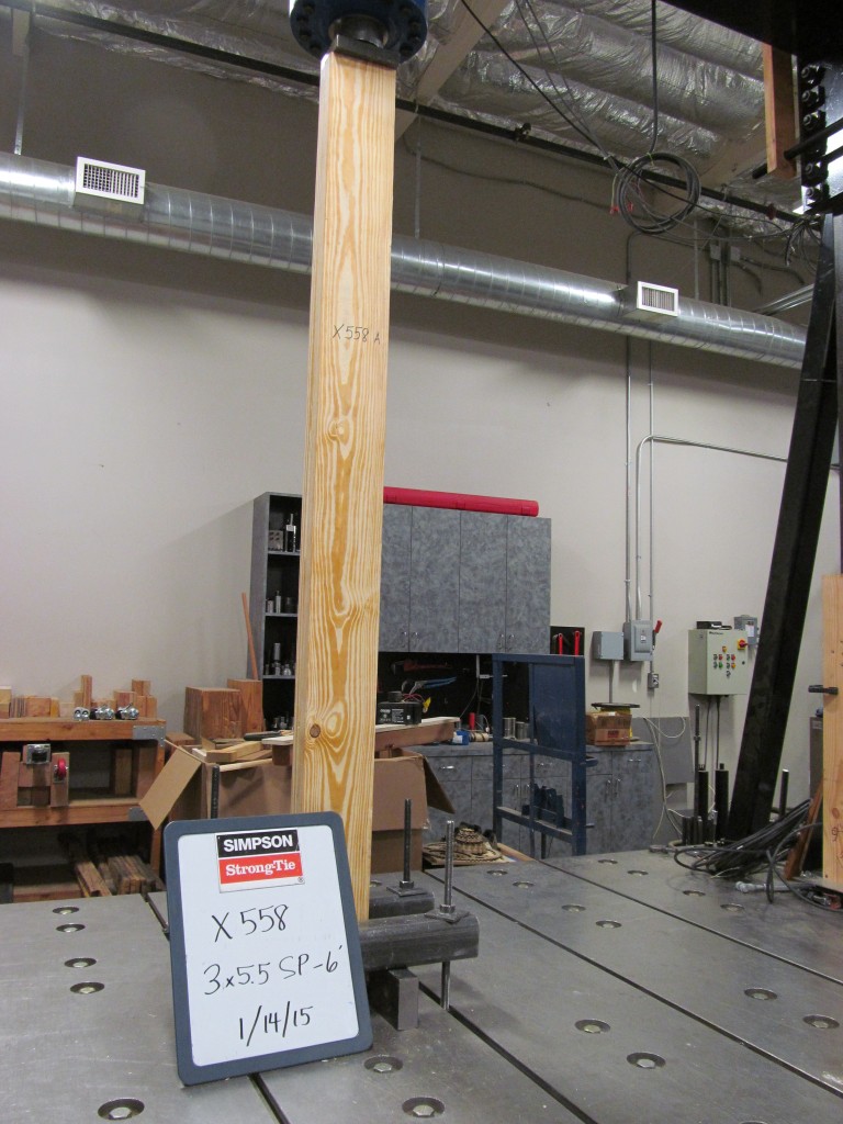
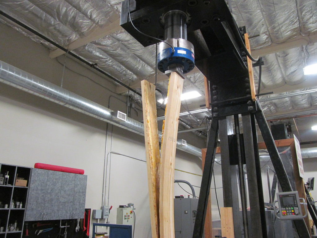
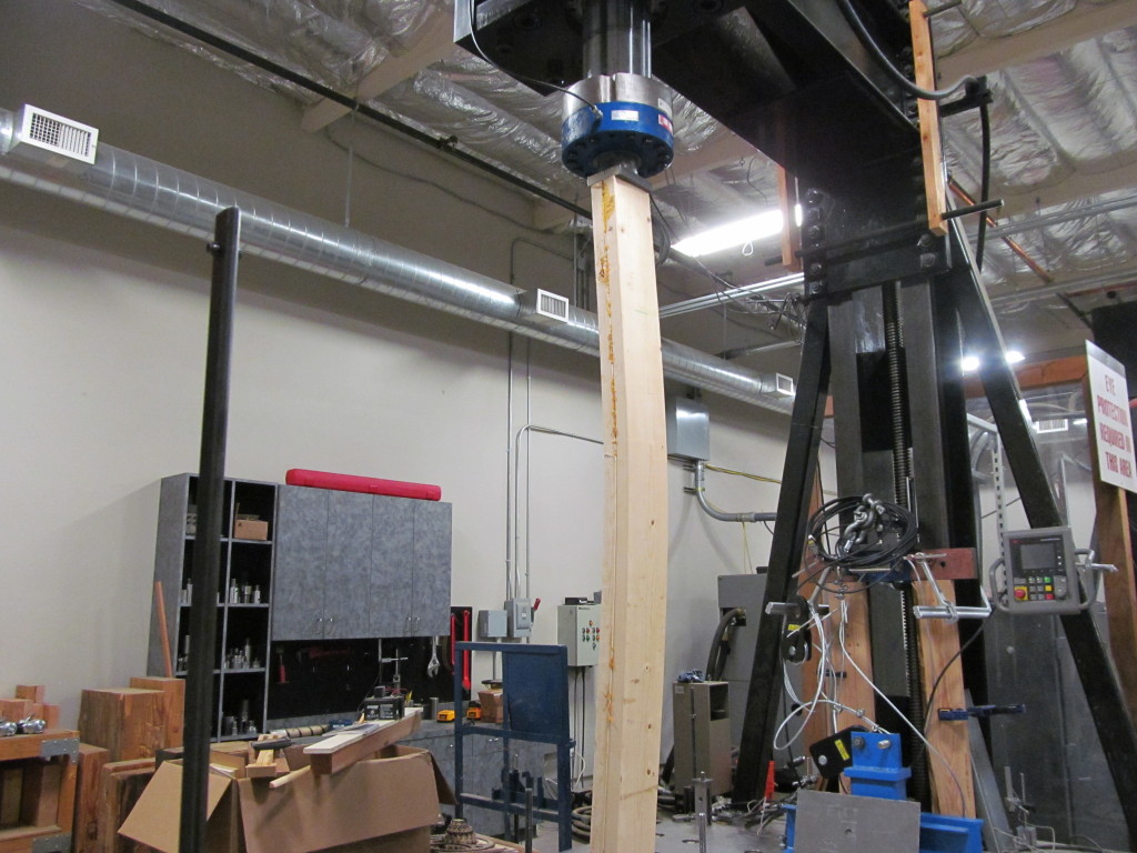
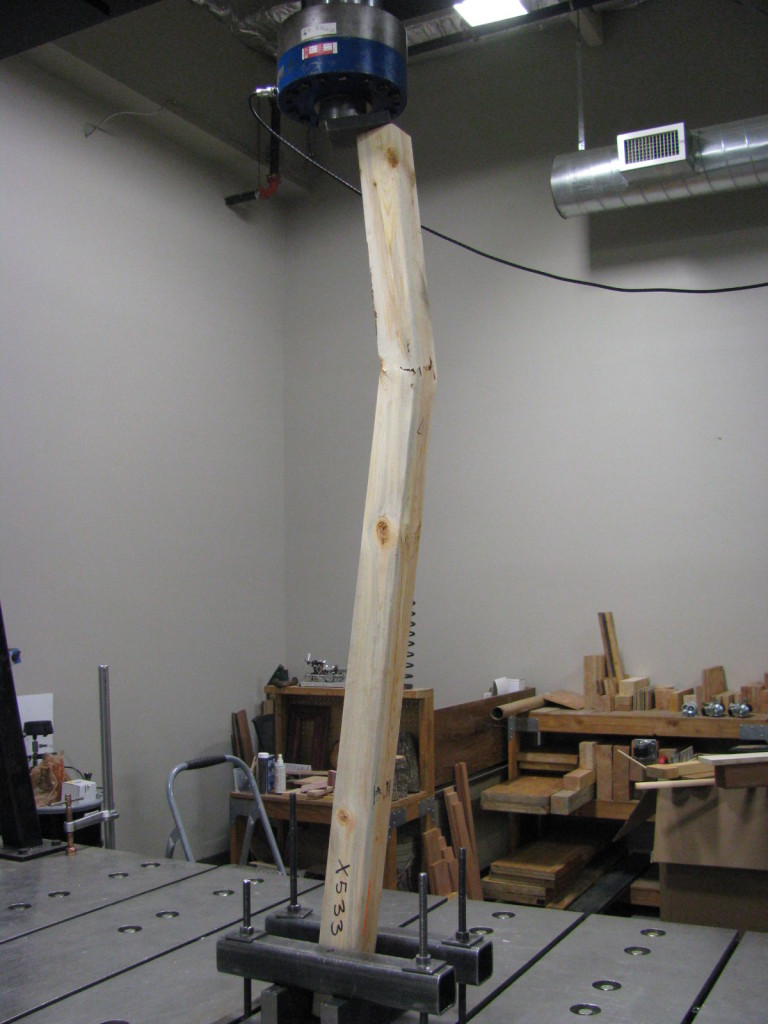
In the last couple of months, our connector test lab ran a number of built-up post compression tests. We were looking for data to compare the performance of built-up posts whose members were fastened with connectors (nails, screws, or bolts) to posts that were glued together.

Southern Pine Built Up Setup
Southern Pine Built-up Setup


Southern Pine Built Up Failure
Southern Pine Built-up Failure


Spruce-Pine-Fir 2x6 Built Up Post
Spruce-Pine-Fir 2×6 Built-up Post


Spruce-Pine-Fir 2x4 Built Up
Spruce-Pine-Fir 2×4 Built-up Post

Our test presses have compression capacities ranging from 100 kips to 200 kips. While we have tested some really heavy connectors, most of our tests are under 50 kips ultimate load. The built-up post testing was exciting to watch as loads got as high as 180 kips and had some very dramatic failures. More fun than the bowling balls, but a little more difficult to contain the explosions.

I have no numbers to share from this testing, as design procedures exist in the code for built-up posts. A few non-technical things we learned from doing this built-up post testing include:

  • Short posts can take a lot of load
  • Regular wood glue requires careful application to get good bond over the full area of a board
  • We haven’t mastered glue application
  • Posts can explode
  • Heavy steel plates go flying when posts explode

Not scientific, but fun to watch. The videos were captured on an iPhone by R&D Lab Testing Technician Steve Ziagos. Steve also blogs about Do-It-Yourself projects on our DIY Done Right blog. Enjoy the video.


Innovative Screws Are Replacing Bolts

In the past several years, there has been an increase in the use of screws in applications that have traditionally been reserved for bolts and lag screws. Greater innovation in the wood screw market has caused this shift. Proprietary wood screws now offer many more benefits than commodity bolts and lag screws. Today, this post will discuss some of those benefits.

Continue Reading
Wide Flange Beams in Light Frame Construction

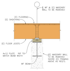
How did that beam get so big? This is what I had to ask myself when I finished sizing and detailing a steel beam that was supposed to fit within the floor joist depth for a flush ceiling. We were removing an unreinforced masonry bearing wall and installing a new wide flange beam to support the existing floor joists as part of a seismic retrofit and remodel. Since the floor joists spliced over the existing bearing wall, it would have been much easier to simply install a new beam below the joists.

Beam below joists
Beam below joists

The architect did not want the beam installed below the framing, as it would protrude too much. Steel design offers multiple wide flange sections that will work for a given loading. For this particular design, I could use a W24x55, a W16x67 or a W14x90. Each has about the same strength (section modulus, Sxx) and stiffness (moment of inertia, Ixx). Without constraints, you would select the lightest section that works. Space limitations that require a shallower beam result in increased beam weight (and cost).

Beam flush with ceiling
Framing hung off beam

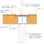
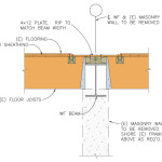
I proposed two solutions for installing the beam in the floor space and hanging the joists off a nailer. One option allowed the steel beam to extend below the floor joists, while the other used a heavier, shallower beam to fit within the space. The owner wanted a flat ceiling and did not mind the added cost for the beam, which weighed about 60% more than the optimum beam size.

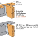
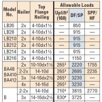
Regardless of space constraints for the design of a steel beam, structural engineers need to specify an appropriate hanger for connecting to the steel beam. Simpson Strong-Tie has many suitable top flange hangers. Most common are hangers that are attached to a wood nailer. Many top flange hangers may also be welded to the beam. Not every nailer solution is rated for uplift, so choose a hanger that meets your requirements. Uplift for welded hangers is addressed in a Simpson Strong-Tie® technical bulletin, T-WELDUPLFT.

Hanger Install
Hanger Install
Nailer Table
Nailer Table

Installers may also wish to connect the hangers using powder-actuated fasteners in lieu of welding. Allowable loads for several of our top flange hangers are addressed in an engineering letter, ITS, MIT, LBV, and BA Hangers Installed on a Steel Header with Powder-Actuated Fasteners.

Of course, as with all of our hanger loads, we created those loads by running a lot of tests.

BA, MIT and ITS Hanger Tests

What are your thoughts on beam selection and installation? Let us know in the comments below.

Podium Anchorage – Structure Magazine

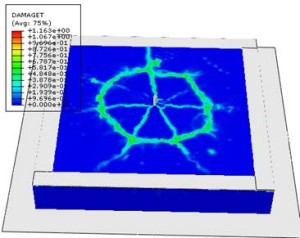
It is hard to believe it has been almost two years since I posted The Anchorage to Concrete Challenge – How Do You Meet It? That post gave a summary of the challenges engineers face when designing anchorage to concrete. Challenges include just doing the calculations (software helps), developing a high enough load, satisfying ductility requirements or designing for overstrength. Over the past several years, Simpson Strong-Tie has worked closely with the Structural Engineers Association of Northern California (SEAONC) to help create more workable concrete anchorage solutions for light-frame construction.

Anchor FEA
Anchor FEA
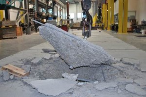
Anchor Breakout
Anchor Breakout
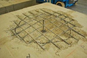
Anchor Close Up
Anchor Close Up

This month’s issue of Structure magazine has an article, Testing Tension-Only Steel Anchor Rods Embedded in Reinforced Concrete Slabs, which provides an update on the ongoing work of SEAONC and Simpson Strong-Tie. The goal of the testing program is to create a useful design methodology that will allow structural engineers to develop the full tensile capacity of high-strength anchor rods in relatively thin (10” to 14”) podium slabs.

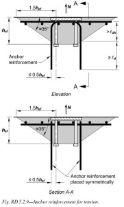
Anchor capacity is limited by steel strength, concrete strength, embedment depth, and edge distances. One way to achieve higher anchor strengths is to design anchor reinforcement per ACI 318-11 Appendix D.

ACI318-11 Figure RD.5.2.9
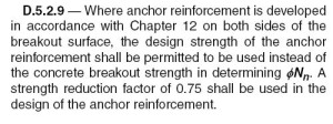
ACI318-11 D.5.2.9
ACI318-11 D.5.2.9

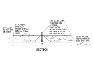
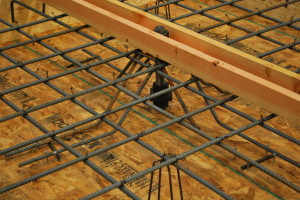
Section D.5.2.9 requires anchor reinforcing to be developed on both sides of the breakout surface. Since this is not practical in thin podium slabs, alternate details using inclined reinforcing perpendicular to the breakout plane were developed and tested.

Anchor Reinforcing Drawing
Anchor Reinforcing Layout

This month’s Structure magazine article summarizes the test results for anchors located at the interior of the slab, away from edges. Additional testing is needed for anchor solutions at the edge of slab. The anchor reinforcement concepts are similar, yet additional detailing is required to prevent side-face blowout failure modes. This testing is in progress at the Tyrell Gilb Research Laboratory and will be completed later this year.

Did you read the Structure article? What are your thoughts?

Statics and Testing

The first time I had to deal with a statics problem was first semester physics. It wasn’t too crazy – something like levers to introduce the concept of balance of forces and moments. Later, we would enjoy an entire semester-long course dedicated to statics. Beam analysis, trusses, multiple point loads, concentrated moments and other tricks Professor Meyer threw at us during his infamous Friday morning pop quizzes. It was a 7 am class, so quizzes were on Friday to make sure we showed up.

Physics textbooks
I still use these.


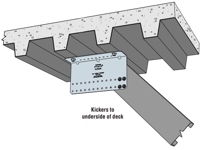
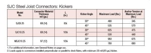
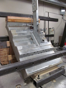
A few weeks back, we were developing anchor reactions for the new SJC steel-joist connectors when used in a kicker application. We wanted to publish anchor reactions for the given connector allowable loads so engineers could skip that step in the calculations.

SJC Steel-Joist Connector – Kicker Application


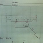
First step was a lot like statics class. Draw a free body diagram with loads and resolve the reactions. A simple model ignoring eccentricity gave us a load we knew was too small. Adding eccentricity and prying forces gave us a load that seemed way (way!!) too large. We used finite element models to better understand the forces in the connection.
Hand Sketch
Modelling the Connection
FEA Model
Modelling the Connection



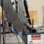
Of course, there is no substitute for physical testing. So we also designed a test setup to capture the anchor tension forces directly. Eliminating as much friction from the setup as possible required some precision machining, several rounds of trial and error and a lot of patience from the lab technicians building everything. The mechanics of the final setup are fairly straightforward. The anchor rods attach to the blue load cells, which measure the tension forces in the rod directly.

SJC Setup
SJC Setup
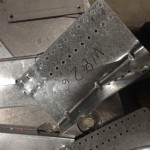
SJC Post Test
SJC Post Test


SJC Steel-Joist Connector Kicker Loads


The test results correlated very well with the original FEA models. I still marvel at the number of tests that go into creating one number for a load table. Of course, even knowing the anchor forces, we still ran a series of tests in metal deck – just to be sure.

Let us know what you think about the testing in the comments below.

SJC in Metal Deck
SJC in Metal Deck


Narrow Face Installations

Engineered wood products have been used in wood-framed construction for many decades. Early forms of engineered wood include plywood as replacement for 1x wood sheathing and glu-laminated beams that could be fabricated in larger sizes with optimized material utilization. I-joists utilizing deep plywood webs and solid sawn lumber flanges solved the challenge of longer floor spans. Oriented strand board (OSB) eventually replaced plywood in the webs, while the innovation of laminated veneer lumber (LVL) became common in the flange material.

In addition to I-joists, structural composite lumber is widely used as a replacement for solid lumber. This could be for a number of reasons such as availability of longer lengths, straighter sections and higher strengths. Structural composite lumber (SCL) may be LVL, parallel strand lumber (PSL), laminated strand lumber (LSL) or oriented strand board (OSB).

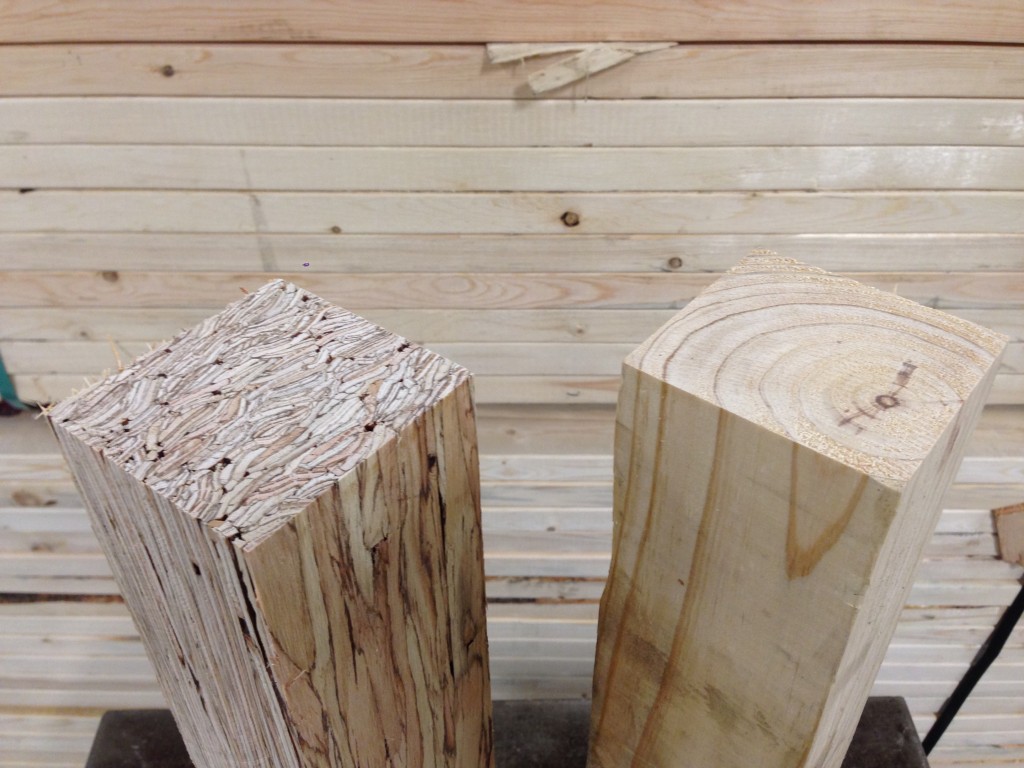
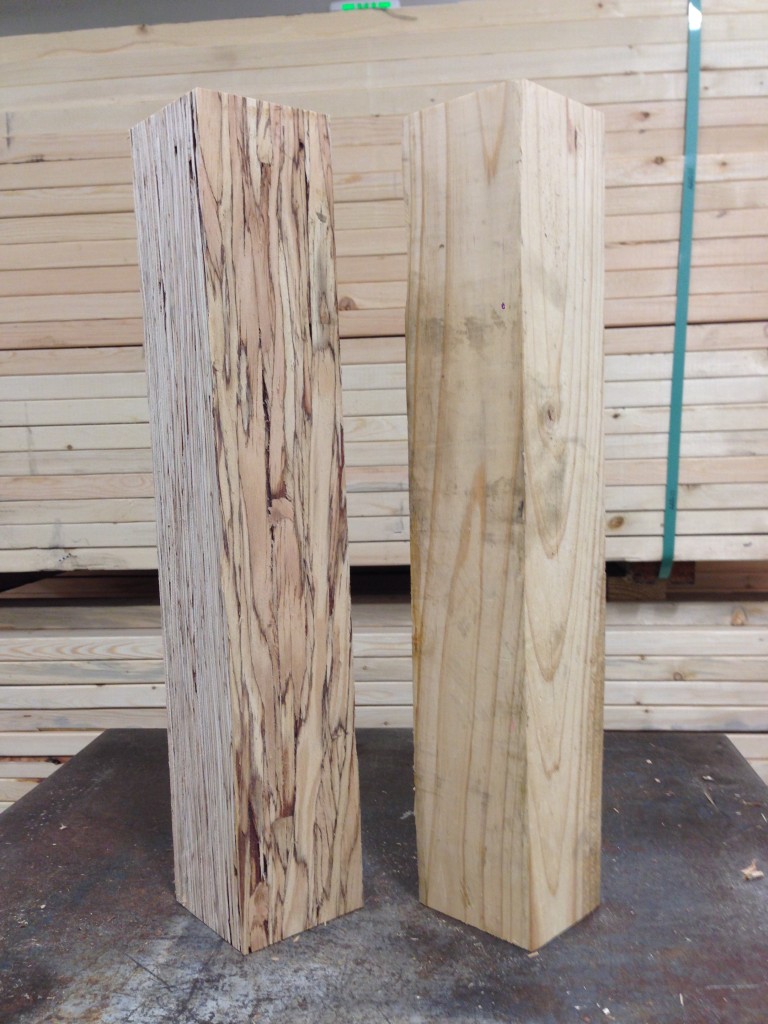
Douglas fir and PSL Post


Structural composite lumber has two faces. If the cross-section is rectangular, say 3½x5¼, the narrow face will show the edges of the SCL layers. In a square section, the face that shows the SCL layers is still referred to as the narrow face. Fasteners will have lower performance when they are installed in the narrow face of SCL. While this is not an issue for beams, Simpson Strong-Tie connectors such as post bases, column caps or holdowns may have reduced allowable loads when installed on the narrow face of SCL columns.

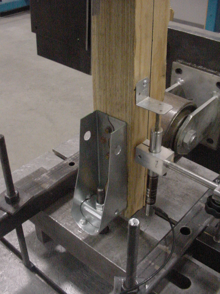
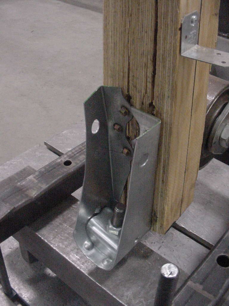
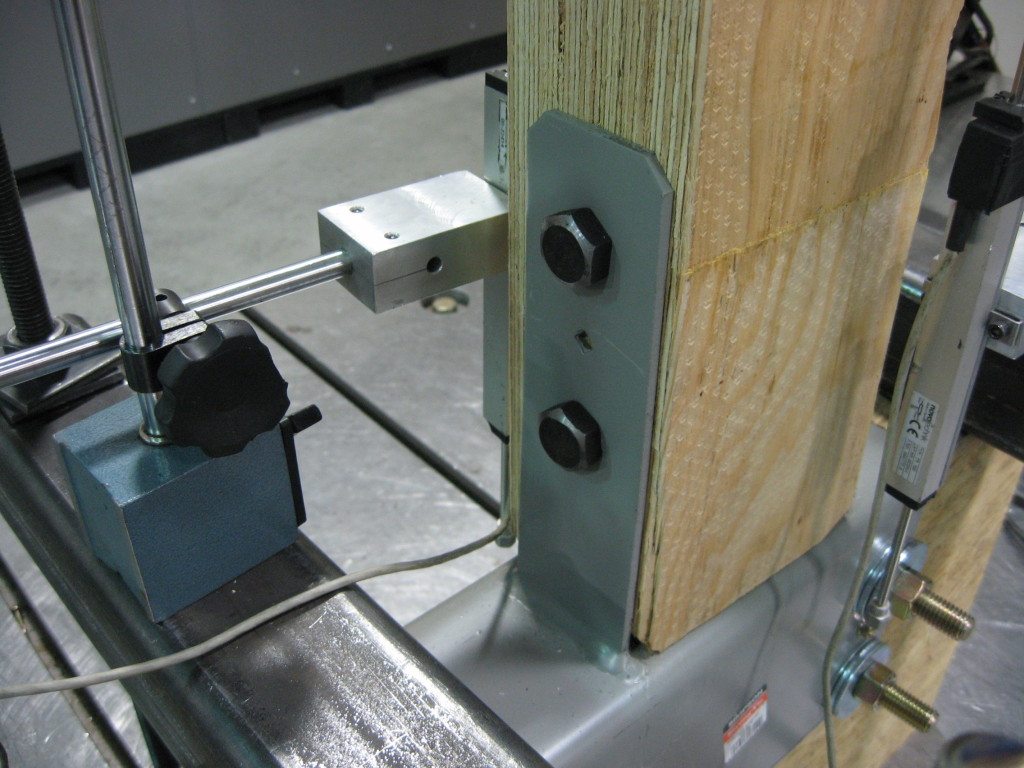
Test setup and failure mode of HDU installed on LVL
CC Column Cap Setup on LVL

To support the use of Simpson Strong-Tie connectors installed on SCL post material, we have run many tests over the years.  The reductions are published in the technical bulletins, T-SCLCLM13 (U.S. version) and T-C-SCLCLMCAN13 (Canada version). The reduction factors range from 0.45 to 1.0, and vary based on SCL material type – LSL, PSL, or LVL – and also by connector and fastener type.

It is important to understand the magnitude of the reductions. While narrow face installations may be unavoidable, engineers will need to specify the correct lumber and hardware combination to meet the design loads.

Share additional thoughts by leaving a comment.

How to Safely Select Nail Substitutions for Connectors

A few days ago, I was speaking to a customer about an application using nail substitutions for a joist hanger installation. Her questions come up often, so I thought I would dedicate a blog post to some of the resources available that cover the use of different nails in connectors.

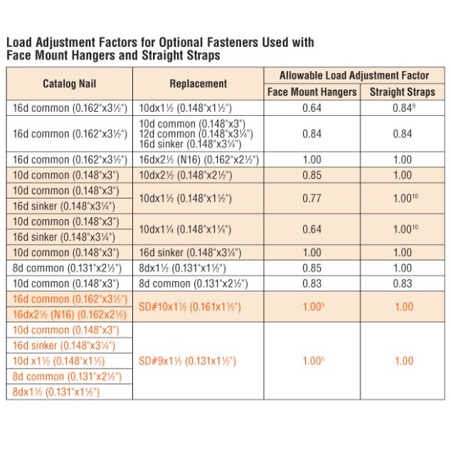
Designers and builders often wish to use different fasteners than the catalog specifies. The application could require short nails that don’t penetrate through the back of a ledger or they want to use screws or sinker nails for easier installation. The Wood Connectors Catalog provides multiple options for alternate nailing for face mount hangers and straight straps on page 27.

Fastener Reduction Factors

The load adjustments for alternate fasteners cover substitutions from a common diameter of 16d to a 10d, or a 10d to an 8d. Multiple different replacement lengths are also covered, with reduction factors ranging from 0.64 to 1.0.

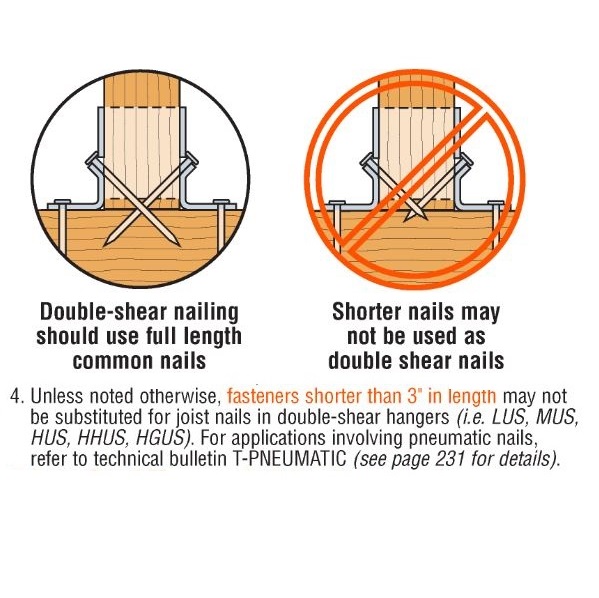
It is important to remember that double shear hangers require 3” minimum joist nails. Short nails installed at an angle in double shear hangers will not have adequate penetration into the header.

Fastener - Double Shear
Fastener – Double Shear

Pneumatic nail guns used for connector installation are commonly referred to as positive placement nail guns. These tools either have a nose piece that locates connector hole, or the nail itself protrudes from the tool so that the installer can line the nail up with the hole. Most positive placement tools do not accept nails longer than 2½”, so framers using these tools will want to use 1½” or 2½” nails. To accommodate installers using pneumatic nails, we have a technical bulletin T-PNUEMATIC. This bulletin provides adjustment factors for many of our most common embedded holdowns, post caps and bases, hangers and twist straps.

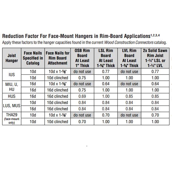
The question of nail size also comes up when attaching hangers to rim board, which can range from 1” to 1¾”. The adjustment factors in C-2013 don’t necessarily apply with rim board, since the material may be thinner the length of the nails used. We also have a technical bulletin for that application – T-RIMBDHGR.

Rim Board Reduction Factors

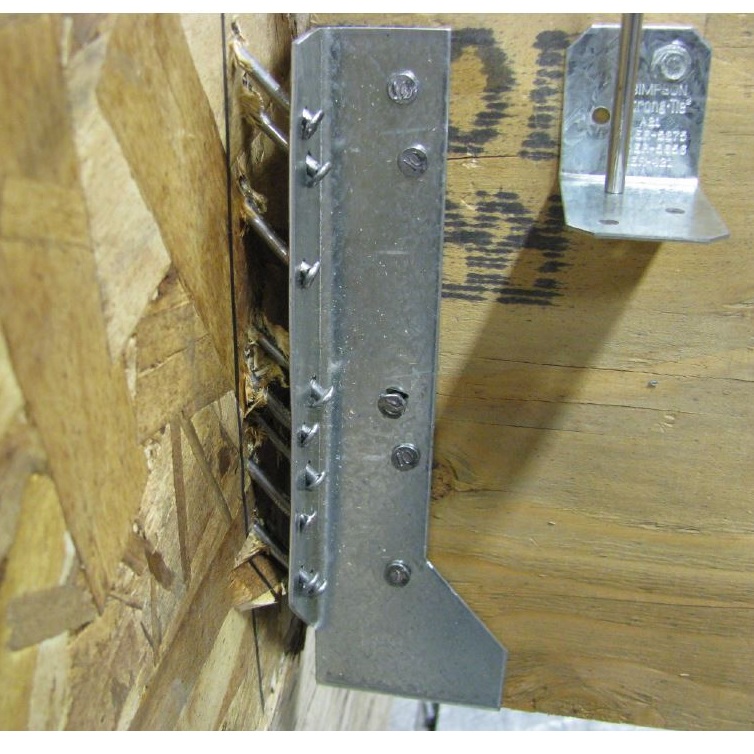
Several of the reduction factors are the same as those in the catalog. Testing of hangers with 10dx1½ nails on 1” OSB or 1¼” LVL did not do as well, however. We observed that once the nails withdrew a little bit under load, they quickly lost capacity. For that reason, we recommend full length 10d or 16d nails on those materials.

Rim board failure
Rim board failure

Understanding that alternate fasteners are available for many connectors can help you pick the right fastener for you application. When you specify a connector, it is important to also specify the fasteners you require to achieve your design load.

NOVA airs episode featuring Strong Frame® Special Moment Frame Testing for NEES-Soft

SEP_3617_group_photoNOVA, the highest rated science series on television, recently aired a segment on the Colorado State University-led NEES-Soft project that tested Simpson Strong-Tie® Strong Frame® special moment frames as a seismic retrofit solution for soft-story buildings. Simpson Strong-Tie and our special moment frame were prominently featured in the clip. You can watch the entire “Making Stuff Safer” episode on PBS here.