They say you never forget your first love. Well, I remember my first earthquake, too. My elementary school had earthquake and fire drills often, but the Livermore Earthquake in January, 1980 was the first time we had to drop and cover during an actual earthquake. The earthquake occurred along the Greenville fault and over 20 years later, I was the project engineer for an event center not far from this fault. I don’t think that earthquake that led me on the path to become a structural engineer. I was only seven and was more focused on basketball and Atari games than future fields of study.
My favorite part about the Livermore Earthquake was the 9-day sleepover we managed to negotiate with my parents. I have a big family, so we had a large, sturdy dinner table. My brother Neil and I convinced my parents it would be better if we slept under the table, in case there was an aftershock. And, of course, we should invite our friends, the Stevensons, to sleepover because they don’t have as large a dinner table to sleep under at their house. And it worked! In our defense, there were a lot of aftershocks and an additional earthquake a few days later.
Each year, an earthquake preparedness event known as the Great ShakeOut Earthquake Drill takes place around the globe. The event provides an opportunity for people in homes, schools, businesses and other organizations to practice what to do during earthquakes.
Simpson Strong-Tie is helping increase awareness about earthquake safety and encouraging our customers to participate in the Great ShakeOut, which takes place next Thursday on October 15. It’s the largest earthquake drill in the world. More than 39 million people around the world have already registered on the site.
Earthquake risk is not just a California issue. According to the USGS, structures in 42 of 50 states are at risk for seismic damage. As many of you know, we have done a considerable amount of earthquake research, and are committed to helping our customers build safer, stronger homes and buildings. We continue to conduct extensive testing at our state-of-the-art Tye Gilb lab in Stockton, California, and next Wednesday, we’ll be performing a multi-story wall shake table test for a group of building officials at our lab. We are also working with the City of San Francisco to offer education and retrofit solutions to address their mandatory soft-story building retrofit ordinance and have created a section on our website to give building owners and engineers information to help them meet the requirements of the ordinance.
Seismic damage to a soft-story building in San Francisco.
Our research is often in conjunction with academia. In 2009, we partnered with Colorado State University to help lead the world’s largest earthquake shake table test in Japan, demonstrating that mid-rise wood-frame buildings can be designed and built to withstand major earthquakes.
Earthquake articles like the one from The New Yorker also remind us how important it is to retrofit homes and buildings and to make sure homes, businesses, families and coworkers are prepared.
Like others in our industry, structural engineers play a role in increasing awareness about earthquake safety. We’d like to hear your thoughts about designing and retrofitting buildings to be earthquake resilient. Let us know in the comments below. And if your office hasn’t signed up for the Great ShakeOut Earthquake Drill, we encourage you to do so by visiting shakeout.org.
This week’s post comes from Brad Erickson, who is the Engineering Manager for the Composite Strengthening Systems™ product line at our home office. Brad is a licensed civil and structural engineer in the State of California and has worked in the engineering field for more than 17 years. After graduating from Cal Poly, San Luis Obispo with a B.S. in Architectural Engineering, he worked for Watry Design, Inc. as an Associate Principal before coming to Simpson Strong-Tie. Brad is the Engineering Manager for Composite Strengthening Systems and his experience includes FRP design, masonry and both post-tensioned and conventional concrete design. While not at work, Brad enjoys spending time carting his three kids around to their competitive soccer games and practices.
Have you ever had a concrete or masonry design project where rebar was left out of a pour? Chances are, the answer is yes. Did you wish you could solve this problem by putting rebar on the outside of that element? That’s exactly what Simpson Strong-Tie Composite Strengthening Systems™ (CSS) can do for you and your project. In effect, composites act like external rebar for your concrete or masonry element. Composites can be used in similar configurations to rebar but are applied on the exterior surface of the element being strengthened.
The initial offering in our CSS line is our fiber-reinforced polymer (FRP) product group. An FRP composite is created by taking carbon or glass fabric and saturating it with a two-part epoxy which, when cured, creates the composite. Together, the weight of the fabric and the number of layers in the composite determine how much strength it will add to your concrete or masonry element.
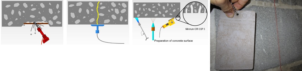
Another form of FRP composite is a precured carbon laminate. The carbon fibers are saturated in the manufacturing facility and are attached to the structure using CSS-EP epoxy paste and filler, an epoxy with a peanut butter–like consistency. We also carry paste profilers (pictured below) that help contractors apply the proper amount of paste to a piece of precured laminate.
Of course, before any concrete or masonry reinforcement project can succeed, proper surface preparation is of the utmost importance. Without a good bond with the substrate, a composite will not be able to achieve the intended performance. Concrete voids must be repaired, cracks must be injected and sealed, and any deteriorated rebar must be cleaned and coated. Prior to composite placement, the surface of the substrate must be prepared to CSP-3 (concrete surface profile) in accordance with ICRI Guideline No. 310.2. Grinding and blasting are the most common surface-preparation techniques.
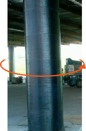
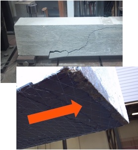
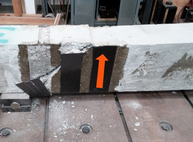
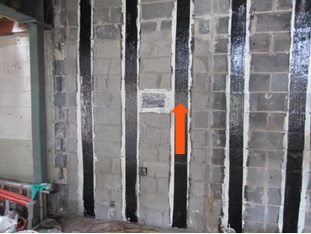
The following are just a few applications where composites can be used for concrete and/or masonry retrofits. The orange arrows show the direction of the fibers in the fabric – in other words, the direction in which the composite provides tension reinforcement.
This is a summary of the basics of composites and their installation on strengthening projects. As composites are not yet in the design codes in the United States, the American Concrete Institute has produced 440.2R-08: Guide for the Design and Construction of Externally Bonded FRP Systems for Strengthening Concrete Structures. This guide has numerous recommendations for using fiber-reinforced polymer systems to strengthen your concrete or masonry construction.
If you would like more information about FRP design, you can learn the best practices for fiber-reinforced polymer (FRP) strengthening design during a recorded webinar offered by Simpson Strong-Tie Professional Engineers. We look at FRP components, applications and installation. We also take you behind the scenes to share the evaluation process informing a flexural beam-strengthening design example and talk about the assistance and support Simpson Strong-Tie Engineering Services offers from initial project assessment to installation.
In this free webinar we dive into some very important considerations including the latest industry standards, material properties and key governing limits when designing with FRCM.
Continuing education credits will be offered for this webinar.
Participants can earn one professional development hour (PDH) or 0.1 continuing education unit (CEU).
For complete information regarding specific products suitable to your unique situation or condition, please visit strongtie.com/rps or call your local Simpson Strong-Tie RPS specialist.
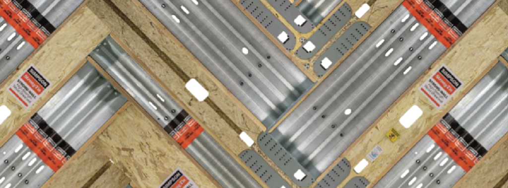
Simpson Strong-Tie is sponsoring the 24th Short Course on Cold-Formed Steel Structures hosted by the Wei-Wen Yu Center for Cold-Formed Steel Structures (CCFSS). The course will be held on October 27-29, 2015 at the Drury Plaza Hotel at the Arch in St. Louis, MO.
This three-day course is for engineers who have limited or no experience designing with cold-formed steel (CFS), as well as those with experience who would like to expand their knowledge of cold-formed steel structural design. Lectures will be given by industry-recognized experts Roger LaBoube, Ph.D., P.E., and Sutton Stephens, Ph.D., P.E., S.E. The course is based on the 2012 AISI North American Specification for the Design of Cold-Formed Steel Structural Members and the 2012 North American Standards for Cold-Formed Steel Framing. Dr. Wei-Wen Yu’s book Cold-Formed Steel Design (4th Edition) will be a reference text.
The course will address such topics as design of wall studs, floor joists, purlins, girts, decks and panels. It is eligible for 2.4 Continuing Education Units (CEUs). Advance registration is requested by October 10, 2015. For more information and to register, click here.
While the contents of this blog are certainly not what Abraham Lincoln had in mind when he made the statement that I’m using to title this blog post, it does speak volumes to the pertinence of what will be discussed today. “Design by others” or some variation of this appears in many parts of Simpson Strong-Tie details.Continue Reading
As soon as news spread that 7.8-magnitude and 7.3-magnitude earthquakes struck Nepal in April and May of this year, earthquake structural engineering experts from our firm, Miyamoto International, hopped on planes from three countries to offer assistance. We do this in hopes that our expertise and technical advice might help stricken communities recover; help them to build better and ultimately help save lives.Continue Reading
This year, the new 5th Edition of the Florida Building Code was released and is now in effect statewide. First printed in 2002, the Florida Building Code was developed as part of Florida’s response to the destruction caused by Hurricane Andrew and other hurricanes in the state.
Another component, which I would like to take a closer look at in today’s post, is a separate Florida Product Approval system designed to be a single source for approval of construction products for manufacturers, Designers and code enforcers. This single system streamlines the previous approach of different procedures for product approval in different jurisdictions. While statewide approval is not required, many jurisdictions, manufacturers and specifiers prefer using the statewide system to the alternative, which is called local product approval. To ensure uniformity of the state system, Florida law compels local jurisdictions to accept state-approved products without requiring further testing and evaluation of other evidence, as long as the product is being used consistent with the conditions of its approval.
The rules of the Florida Product Approval system are in Florida Rule 61G20-3. Here is some basic information about Florida Product Approval.
The Florida Product Approval system is only available for “approval of products and systems, which comprise the building envelope and structural frame, for compliance with the structural requirements of the Florida Building Code.” So users will only find certain types of products approved there. However, if you work in areas where design for wind resistance is required, the Florida system can be a gold mine of information for tested, rated and evaluated products. Not only will you find products like Simpson Strong-Tie connectors with our ICC-ES and IAPMO UES evaluation reports, but thousands of other tested and rated windows, doors, shutters, roof covering materials and other products that don’t typically get evaluation reports from national entities. The specific categories of products covered under the Florida system are exterior doors, impact protective systems, panel walls, roofing, shutters, skylights, structural components and windows.
To protect consumers, a recent law passed in Florida states that a product may not be advertised, sold or marketed as offering protection from hurricanes, windstorms or wind-borne debris unless it has either State Product Approval or local product approval. Selling unapproved products in this way is considered a violation of the Florida Deceptive and Unfair Trade Practices Act.
Once a manufacturer understands the process for achieving a statewide approval, it is not difficult to achieve, but it can be expensive. The manufacturer must apply on the State of Florida Building Code Information System (BCIS) website at www.floridabuilding.org. To prove compliance with the code, the manufacturer must upload either a test report, a product certification from an approved certification entity, an evaluation report from a Florida Professional Engineer or Architect, or an evaluation report from an approved evaluation entity (ICC-ES, IAPMU UES, or Miami-Dade County Product Control). Then, the manufacturer must hire an independent validator to review the application to ensure it complies with the Product Approval Rule and that there are no clerical errors. Finally, once the validation is complete, staff from the Department of Business and Professional Regulation reviews the application. Depending on the method used to indicate code compliance, the application may be approved at that time or it may have to go through additional review by the Florida Building Commission.
Here are several ways to find out if a product is approved.
For Simpson Strong-Tie products, we maintain a page on www.strongtie.com that lists our Florida Product Approvals.
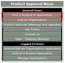
On the menu on the left side of the page, click on Product Approval. Or, click this link to go directly to the search page.
On the Product Approval Menu, click on Find a Product or Application. Note that at this location you can also search for approved organizations such as certification agencies, evaluation entities, quality assurance entities, testing laboratories and validation entities.
Ensure the proper Code Version is shown. The current 2014 Florida Code is based on the 2012 International Codes.
At this point, several options can be searched. You can search for all approvals by a specific product manufacturer or a certain type of building component by searching Category and Subcategory, or if searching for a specific product, by entering the manufacturer’s name and the product name.
Select the option highlighted in red
I hope you find the information contained in the Florida Product Approval system useful. Do you have other needs to find approved products?
This week’s post comes from Marlou Rodriguez who is an R&D Engineer at our home office. Prior to joining Simpson Strong-Tie, Marlou worked as a consulting engineer. His experience includes commercial, multi-family residential, curtain wall systems and the design of seismic bracing for non-structural components. Marlou is a licensed professional Civil and Structural Engineer in California, and too many other states to list. He received his bachelor’s degree in Architectural Engineering from Cal Poly San Luis Obispo. Here is Marlou’s post.Continue Reading
This week’s post is a case study featuring a recent restoration job on the central coast of California and how Simpson Strong-Tie® hot-dipped galvanized screws proved to be a better option than traditional spikes.
A pier originally constructed in the 1800s was closed a few years ago as general deterioration caused the structure to become unsafe. As preparation for rebuilding the pier began, one of the major concerns was the attachment of the deck boards to the framing.
Traditionally, the deck boards have been attached with hot-dip galvanized 60d (0.283″ x 6″) spikes. However, spikes have a low withdrawal resistance, are typically predrilled and have a multi-step installation process. In addition, spikes, over time, can begin to back out so that the heads protrude above the top of the deck boards. This creates an unsafe condition for pedestrians and also results in ongoing maintenance work. Here you can see one of the old spikes.
Corroded spike for deck board fastening.
Simpson Strong-Tie provided two options for replacing these spikes: the Strong-Drive® Timber-Hex HDG screw, SDWH27800G, and its stainless-steel counterpart, the Strong-Drive Timber-Hex SS screw, SDWH27800SS. The SDWH27800G screw measures 0.276″ x 8″ and has a hot-dip galvanized coating, conforming to ASTM A153 Class-C. The SDWH27800SS screw measures 0.276″ x 8″ and is made from Type 316 stainless steel. Both of these screws have integral washer, hex-drive heads and are self-drilling. They are not intended to be self-countersinking though, and as a result, installation with the heads below the deck surface requires a shallow dapped hole.
A comparison of the load values was provided to Shoreline Engineering, Inc. engineers Bruce S. Elster, P.E., and Jonathan T. Boynton, P.E., for their review and approval. In addition, Simpson Strong-Tie Fastening Systems/Dealer Sales Representative Darwin Waite expertly conducted on-site demonstrations for numerous decision makers including the contractor and city officials. These demonstrations allowed the contractor and owners to compare the labor costs and finished appearance of the different fastening methods.
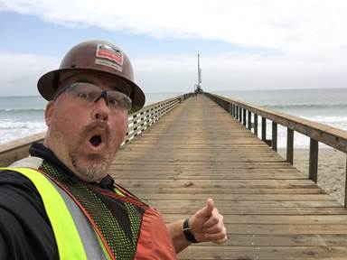
Simpson Strong-Tie Fastening Systems Dealer Sales Representative Darwin Waite takes selfie on the completed dock.
Below is a comparison of the allowable load values* of the potential fasteners. We can see how each of the Simpson Strong-Tie screw options exceeds the spike load values in all load conditions.
Table 1. Comparative allowable properties for hot-dip galvanized spikes (60d), hot-dip galvanized screws (SDWH27600G, SDWH27800G) and stainless steel screws (SDWH27600SS and SDWH27800SS).
*Not to be used for design purposes as footnotes have been left out of this blog post. Table values include wet service factor adjustments.
In the end, the SDWH27800SS stainless-steel screw was specified for the project.
Some might consider a 316 stainless steel screw to be cost prohibitive, but when you factor in the lower cost of installation, the lower maintenance requirements and the actual cost of the fastener, this screw turned out to be the lowest cost alternate. In addition, it provided better withdrawal and lateral load values than the spikes.
This picture shows the deck fastening in progress. The screws are set and ready for driving with screw-driving tools.
The Strong-Drive Timber-Hex SS screws made it possible to complete the deck restoration on time and on budget. Perhaps just as importantly, the pier looks beautiful and should last for many years to come.
Let us know if the comments below if you have any questions about specifying these fasteners for securing decks, docks, pilings and other heavy-duty, coastal applications.
As always, call our Engineering Department if you have any questions.
Have you used the SDWH27800SS screw for a project? Tell us about in the comments below.
In an ideal world, a building is envisioned and a structural engineer begins the structural design. When the decision to use roof trusses is made, a component manufacturer is promptly involved in the design process. Using the loads and design parameters from the structural engineer, the trusses are designed and those designs are provided back to the engineer. The structural engineer then incorporates the truss designs into the building, transfers the loads through the structure and designs all the structural elements, bracing and connections necessary to provide a continuous load path down to the foundation. Finally, working from the complete and detailed plans, the contractor constructs the building flawlessly. Perfection!
But let’s get back to reality, where buildings are often designed and ground broken by the time the trusses are designed. The building Designer creates a roof framing plan to analyze and transfer the loads between the roof system and the rest of the building, and then designs the building (from the top plate down) accordingly. The component manufacturer (CM) eventually gets the plans and uses them to create a truss placement diagram and gather the truss design criteria. The CM then communicates the truss design parameters to the truss design engineer, who designs each of the individual trusses. The CM provides those truss designs and the truss placement diagram back to the building Designer. So far so good, right?
If every building were rectangular with a gable-style roof, this process would be fairly simple and hassle-free. But buildings are often more complicated than that. Roof systems can get very complex, so things don’t always go according to plan…such as when a wall that was intended to be non-load bearing gets used as a bearing location for the trusses; or when the CM moves a girder to a different location that works better for the trusses. Or maybe a truss can’t be designed for the entire span and an additional support is needed. In some cases, the CM may even flip the direction of the trusses completely because it results in a more efficient (lower-cost) truss package – that’s better for the building, right?
Changes during the design process can result in additional labor, material and cost. In today’s fast-tracked world, how can these expenses be avoided? Below are some suggestions from a truss Designer’s perspective.
Know each party’s design responsibilities
This may not seem like it has much to do with minimizing changes during the design process, but some problems arise from the fact that there is not always a common understanding of each party’s responsibilities. One misconception is that truss design engineers design an entire roof system, and they design the roof truss system to work within the framework of the building as set forth in the building structural plans. This is not true! Truss design engineers design single components, not systems. They do not even see the building Designer’s plans. It is the CM that receives the construction documents to obtain the truss design criteria and requirements. They in turn communicate the truss design parameters to the truss design engineer.
It is also important to understand the role the truss placement diagram plays in the overall process. This is a commonly misunderstood document, because many people think this is an engineered document prepared by the truss design engineer. Not only do truss design engineers not prepare these documents, they do not even review them. Instead, the CM creates the truss placement diagram after reviewing the construction documents. A truss placement diagram is only intended to identify the assumed location for each truss and serve as a truss installation aid. In fact, the truss industry intentionally changed the description of this document at one point from “truss placement plan” to “truss placement diagram” because the word “plan” has a connotation associated with engineering and design, and a truss placement diagram does not involve either of those.
Understanding how the truss industry operates and the responsibilities each party has in the design process will prevent incorrect assumptions from being made. If you find yourself saying, “I’m sure the truss design engineer will check this and take care of it…,” you probably need to think again.
The clearer the specifications, the better
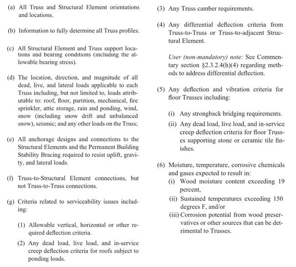
This may seem obvious, but do the construction documents contain all of the information necessary for the preparation of the truss design drawings? ANSI/TPI 1 specifies the required information in the construction documents (see text box below). Anything less than this information will mean assumptions need to be made during the creation of the truss placement diagram and the design of the trusses. The building Designer can also specify additional requirements to help ensure that the trusses they get are the trusses they want. In short, the more complete, accurate and detailed the construction documents are, the better the design process will be.
Required information in the construction documents (excerpted from ANSI/TPI 1-2014)
Review, review, review
It is the building Designer’s responsibility to review (and approve or reject) both the truss placement diagram and the individual truss design drawings for conformance with the overall building design. As mentioned earlier, the truss design engineer is solely responsible for the design of the individual trusses; they do not review the entire truss system and they do not check to see that the truss placement diagram meets the intent of the framing plan and specifications. Further, the component manufacturer relies on the completeness and accuracy of the information in the construction documents to create the truss placement diagram and to communicate the truss design requirements to the truss design engineer. Therefore, the success of the building’s construction depends on the building Designer’s thorough review of the truss submittal package.
Collaboration is key
Building Designers know what is best for the overall building; component manufacturers know what is best for the trusses. The best-case scenario is when the building gets the best of both. This requires collaboration during the planning stages, so that the strengths of both parties can be utilized to their maximum potential. A building Designer who finds out from the CM what the best setback distance is for a particular hip roof will not only minimize changes to the design downstream, but will also likely end up with a lower-cost building. On the other hand, a building Designer who provides some input into the actual truss designs, such as strategically placed webs in a string of trusses, will end up with a more efficient, permanent bracing plan that can even be included in the original construction documents.
Some may think the answer to this design process challenge is to let the building Designers design the trusses themselves; that all they need is the truss design software and they can design the trusses as part of their building design. But the truss industry knows that truss design software cannot replace the ingenuity and creativity of talented CMs who have a passion for what they do; just the same way that engineering software cannot ever replace an experienced engineer. That is why the truss industry continues to work hard to make it easier to collaborate, in lieu of providing truss design software to people outside of the component manufacturing industry. In this way, everyone’s skill sets can be fully utilized.
What do you think about this challenge? Let us know your thoughts in the comments below!
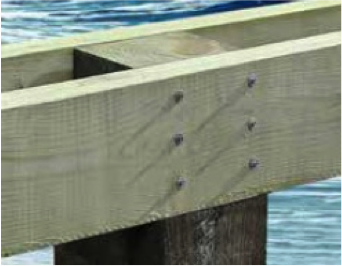
For decades, bolts were used for pile construction to ensure a structurally sound connection. While this works on paper, these types of bolted connections are not user friendly to install in the field. The more difficult the connection is to make, the more likely it won’t be done right.
Many pile connections have stringers or beams on each side of the pile. This means the predrilled hole for the bolt must be properly aligned through all of the parts. It takes considerable strength and the skill and care of a craftsman to do this properly, often from the top of a ladder. Given the large size of many piles, the installer also has to tighten the bolt while blind to the back of the assembly. It can take a few minutes per fastener to get the job done right. These conditions have created a great need in the field for a better approach.
After much design and testing, Simpson Strong-Tie has come out with a new faster and safer solution, the SDWH Timber-Hex HDG screw. The screw has a special point, so no predrilling is required. The installation of this fastener takes a matter of seconds, not minutes. This adds up to hours of saved labor costs.
More information about the SDWH Timber-Hex HDG screw can be found in the newly released flier F-F-SDWHHDG24, which is on our website.
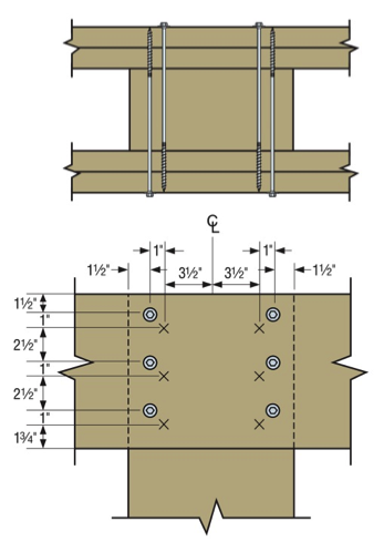
Loads for these screws are presented two ways. First, there are individual fastener connection values based on screw length and wood side-plate thickness. Second, loads are given for entire assembly connections. These loads are based on the testing of specific fastener layouts. Our assembly testing used piles with one or two stringers attached to each side of the pile. Here is an example of a load table for stringer-to-square pile connection loads.
Connection assembly layouts are shown in the F-F-SDWHHDG24 flier for square piles, round piles, piles with continuous stringers and piles with stringers that are spliced at the pile. Here is one example below:
We are testing additional assemblies as other connections, materials and conditions are identified.
If you have a common condition that you don’t see addressed in the flier, please let us know in the comments below. You can also always call us in the Engineering Department if you have questions.
We use cookies on this site to enhance your user experience. By clicking "I AGREE" below, you are giving your consent for us to set cookies. Privacy PolicyI AGREE
Privacy & Cookies Policy
Privacy Overview
This website uses cookies to improve your experience while you navigate through the website. Out of these cookies, the cookies that are categorized as necessary are stored on your browser as they are essential for the working of basic functionalities of the website. We also use third-party cookies that help us analyze and understand how you use this website. These cookies will be stored in your browser only with your consent. You also have the option to opt-out of these cookies. But opting out of some of these cookies may have an effect on your browsing experience.
Necessary cookies are absolutely essential for the website to function properly. This category only includes cookies that ensures basic functionalities and security features of the website. These cookies do not store any personal information.
Any cookies that may not be particularly necessary for the website to function and is used specifically to collect user personal data via analytics, ads, other embedded contents are termed as non-necessary cookies. It is mandatory to procure user consent prior to running these cookies on your website.