


In the past several years, there has been an increase in the use of screws in applications that have traditionally been reserved for bolts and lag screws. Greater innovation in the wood screw market has caused this shift. Proprietary wood screws now offer many more benefits than commodity bolts and lag screws. Today, this post will discuss some of those benefits.
Truss-to-Truss and Truss-to-Everything Else Connections
One of the questions I am asked most frequently is “Who is responsible for the truss-to-(fill in the blank) connection? One such example is the truss-to-wall connection. To answer this question, it helps to recognize there are two types of connections: a truss-to-truss connection and a “truss-to-everything-else-except-a-truss” connection. The Truss Designer is responsible for the former, and the Building Designer is responsible for the latter. Pretty simple, right? So why all the questions?

Some people incorrectly assume the Truss Designer is responsible for connecting the truss to everything the truss touches. Then, when the Truss Designer doesn’t specify a connection to something the truss touches (such as a wall), it prompts the question, “Hey, who is responsible for that connection? I thought the Truss Designer was!” In other cases, the person asking the question is actually challenging the answer, such as “Shouldn’t the Truss Designer be specifying the truss-to-wall connection? Why don’t they?” And finally, the question may be prompted at times when the project doesn’t have a Project Engineer (aka the Building Designer), so the question becomes, “Now who is going to specify that connection? It must be the Truss Designer, right?”
But the Truss Designer isn’t responsible for the truss-to-wall connection – and here’s why. Unless the scope of work has been expanded by contract, the Truss Designer is responsible for designing an individual component. The truss gets designed for a given set of specified loads, environmental conditions, serviceability criteria and support locations, all which are specified by the person responsible for the overall building: the Building Designer. Once designed, the truss will have a maximum download reaction and uplift reaction (if applicable) at each support location. Is that enough information to specify a truss-to-wall connection? No, it is not. First, the Truss Designer may not know what the truss is even sitting on; he or she may only know that the bearing is SPF material and 3 ½” wide. Is it a single top plate or double top plate? Is there a stud below the truss that can be connected to, or is the stud offset? Or, is the truss sitting on a header spanning across a wide window?
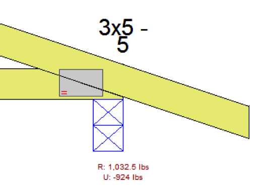
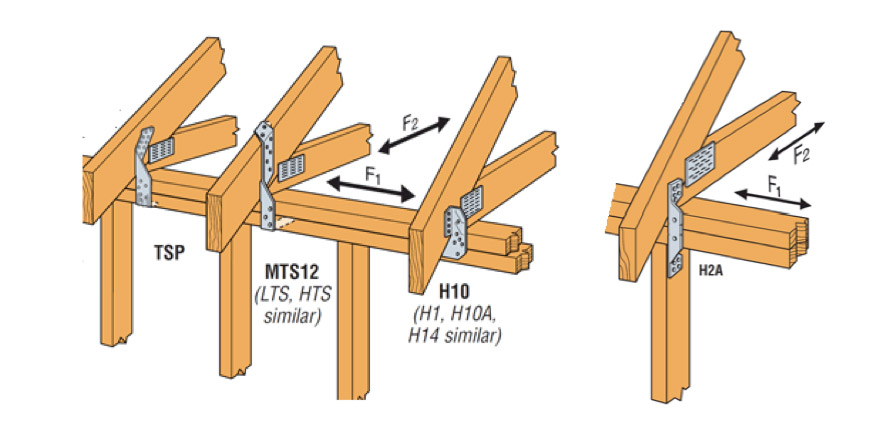
Second, even if the Truss Designer had all of the information regarding the bearing conditions, there is another problem. The Truss Designer has the reactions resulting from the loads applied to the truss. What about the reaction at the top of the wall (perpendicular to the wall) resulting from the lateral loads applied to that wall? And the shear loads acting parallel to the wall as a result of lateral loads applied to the end wall? These loads also need to be resisted by the truss-to-wall connection (hence, the F1 and F2 allowable loads that are published for hurricane ties), so the Truss Designer cannot select an adequate truss-to-wall connection based on the truss reactions alone.
Finally, there’s one more scenario to consider. Say a Building Department requires that truss-to-wall connections must be specified by the Truss Designer on projects that have no Engineer of Record. It wants to ensure trusses are adequately secured to the walls, and the Truss Designer may seem best equipped to determine those connections (this has actually happened in some places). The Truss Designer can find out what exactly the truss is sitting on, and can even calculate some approximate reactions for the top of the wall to conservatively take into account during the selection of the connection. Problem solved? Not entirely. That takes care of the top of the wall, but the load doesn’t stop there. So requiring the Truss Designer to specify the truss-to-wall connection only transfers the problem to the bottom of the wall. Who is going to address those connections?
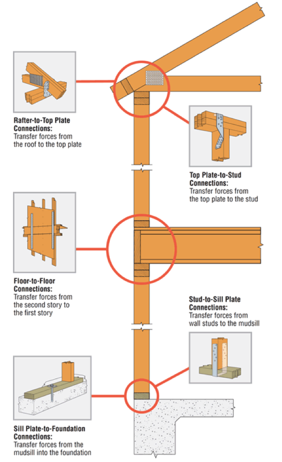
While most people don’t think of the Truss Designer as being the person responsible for the connections at the bottom of the wall, many do think the Truss Designer should be responsible for the connections at the top of the wall. But because someone – namely, the Building Designer – still needs to ensure that a continuous load path has been satisfied by the connections in the building, does it really help to increase the scope of work of the Truss Designer to specify the truss-to-wall connection?
Let us know your thoughts in the comments below.
The Importance of Resilient Communities During Earthquakes
Imagine that it’s 4:30 a.m. and suddenly you’re awakened by strong shaking in your home. Half asleep, you hang on to your bed hoping that the shaking will stop soon. All of a sudden, the floor gives away and you fall. You think, “What just happened? How could this have possibly occurred? Am I alive?”
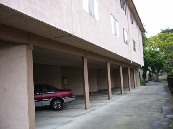
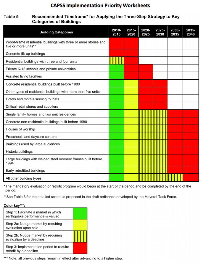
These could have been the thoughts of Southern California residents living in one of the many apartment buildings, which collapsed on January 17, 1994, during a 6.7 magnitude earthquake. The Northridge Earthquake brought awareness to buildings in our communities with a structural weakness known as a soft story, a condition that exists where a lower level of a multi-story structure has 20% or less strength than the floor above it. This condition is prevalent in buildings with tuck-under parking and is found in multistory structures throughout San Francisco, Los Angeles and other cities (see Figure 1). These structures are highly susceptible to major damage or collapse during a large seismic event (see Figure 2).

Soft story retrofits help to strengthen our communities and make them more resilient to major disasters. There are several resources available to structural engineers that need to retrofit weak-story buildings. Some of these resources are mentioned in our September 18 blog post.
During the 2014 SEAOC Convention held in Indian Wells on September 10-13, speakers discussed different methods, analysis and research that address the behavior of various materials and construction types during seismic events along with approaches to retrofit historically poor performing structures. This information can be viewed from the convention’s proceedings available at www.seaoc.org.
On October 20, 2014, the Structural Engineers Association of Southern California (SEAOSC) will be hosting their 4th annual Strengthening Our Cities BAR Summit in downtown Los Angeles. This event brings together many different stakeholders in our built environment, including public officials, building owners and managers, business owners, insurance industry representatives, emergency managers and first responders, and design professionals.
Many prestigious thought leaders, including USGS Seismologist Dr. Lucy Jones will be speaking at the summit, discussing such topics as tools and analysis methods for retrofitting vulnerable buildings and the Building Occupancy Resumption Program (BORP).
Expect a great day full of useful information about ways to strengthen our communities and prepare for major earthquakes as well as opportunities to network with like-minded peers. For additional information and to register, visit www.barsummit.org. We also hope you’ll visit our booth. We look forward to speaking with you there.

Remembering Loma Prieta
We all know that earthquakes physically shape the landscape here in California, but they shape careers as well. Earthquakes I felt while growing up in California’s southern San Joaquin Valley got me thinking about engineering as a career while in high school. When the Loma Prieta earthquake struck on October 17, 1989, like many of you I was watching the World Series live on television and thus got to see the earthquake live as well. I was in my senior year of college at the time, studying Civil Engineering with a structural emphasis. This earthquake cemented the direction I would take in my career. I wanted to be a structural engineer, and I wanted to design buildings that would not fall down in earthquakes.

Fastener Catalog Breakdown: Technical Section LRFD Values
Structures and connections can be designed either using Allowable Strength Design (ASD) method or Load and Resistance Factor Design (LRFD) method. In the ASD method, the allowable strength is calculated by dividing the nominal strength by a safety factor. In the LRFD method, the design strength is calculated by multiplying the nominal strength by the resistance factor. In design, the adjusted ASD design value is compared to a calculated load or stress. As long as the adjusted ASD design value exceeds the calculated load of stress, then the ASD design value is judged safe. In LRFD design, the nominal strength is equated to factored loads. If the factored strength is greater than the factored loads, then the design can be accepted. ASD is the more common method adopted in the professional world.Continue Reading

Applying new FEMA P-807 Weak Story Tool to Soft-Story Retrofit
We have written about San Francisco’s Soft-Story Retrofit Ordinance and Soft-Story Retrofits before on the blog. I wanted to discuss in more detail the issues with soft story buildings and FEMA’s new tool for addressing them. Under the San Francisco Ordinance, wood-framed residential structures that have two or more stories over a “soft” or “weak” story require seismic retrofit. So far, more than 6,000 property owners have been notified about complying with the mandate.Continue Reading
Home Seismic Retrofit
The 6.0 magnitude earthquake that struck Napa, CA, in August caused more than 200 injuries and structural damage to many homes and businesses throughout the area. The quake was the largest to hit the San Francisco Bay Area since the Loma Prieta earthquake (6.9 magnitude) in 1989, prompting the governor to declare a state of emergency.
I have done several posts about San Francisco’s Soft-Story Retrofit Ordinance and some of NEES-Soft testing related to soft-story retrofits. The soft-story ordinance only addresses multi-unit residential units and does not require retrofit of single-family homes. Cities are reluctant to mandate seismic evaluation and retrofit of single-family homes for a number of reasons that I won’t discuss here. The draft Earthquake Safety Implementation Program (ESIP) for San Francisco will not recommend mandatory retrofit of single-family homes until 2030.
The good news is homeowners can retrofit their homes without waiting for the government. A couple years ago in this post, I discussed some of the tools available to retrofit existing buildings.
One of these tools is the 2012 International Existing Building Code (IEBC). The IEBC has provisions for repair, alteration, addition or change of occupancy in existing buildings and for strengthening existing buildings. For alterations, these provisions may not comply with current IBC requirements, but they are intended to maintain basic levels of fire and structural life safety. The IEBC also provides prescriptive provisions for strengthening existing buildings against earthquake damage, which include strengthening residential houses on raised or cripple wall foundations.
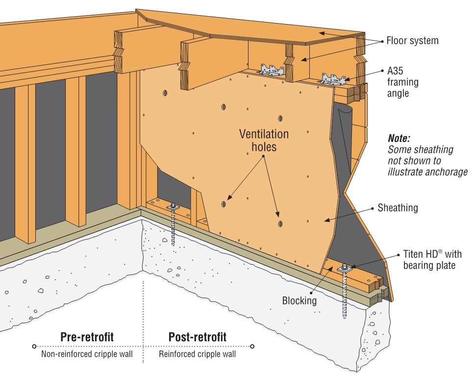
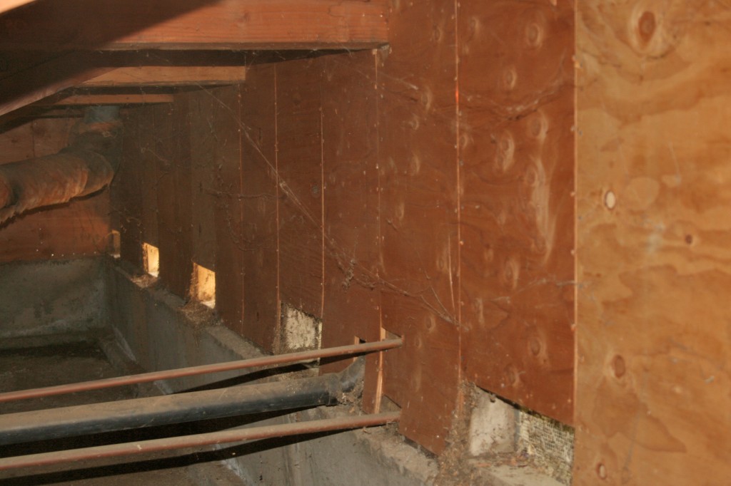
Cripple wall failures are a common type of damage observed in older homes, caused by inadequate shear strength in the cripple wall. An additional failure point is the attachment of the wood sill plate to the foundation. Having a strong connection between the wood structure and the concrete foundation is critical in an earthquake. Since the work required to strengthen these connections is typically performed in a crawlspace or unfinished basement, it is a relatively low-cost upgrade that is extremely beneficial to structural performance.
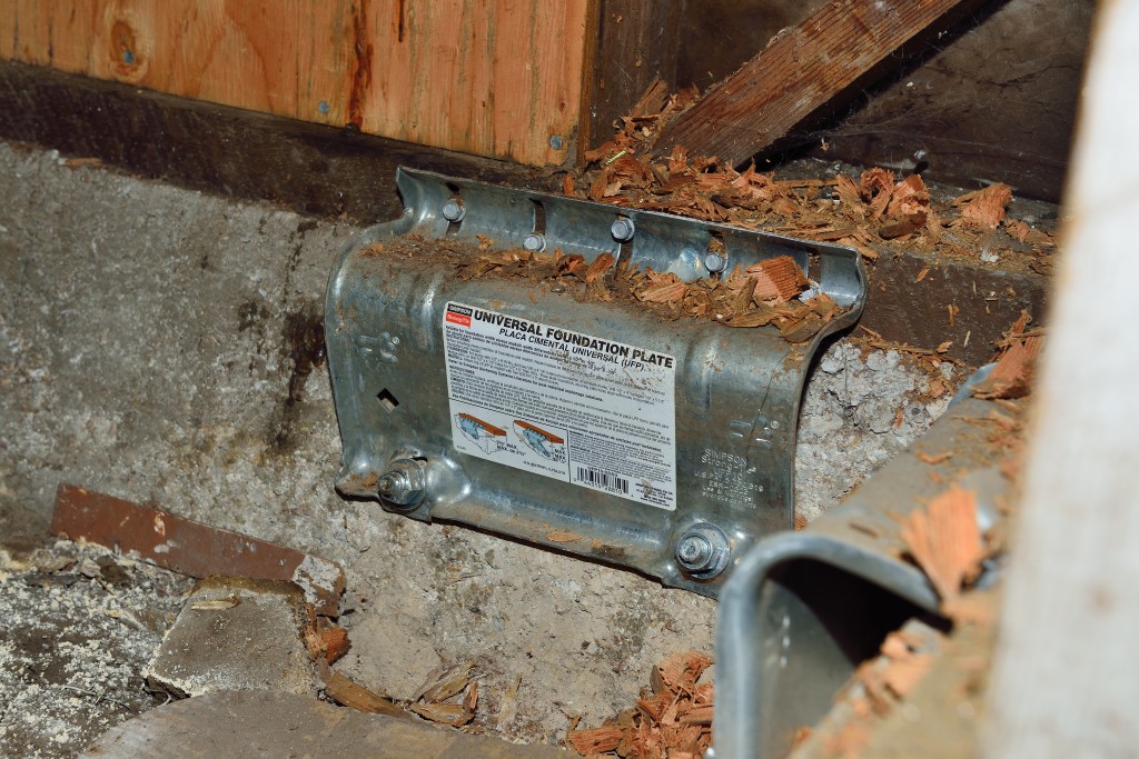
Our website has information for retrofitting your home. The Seismic Retrofit Guide has information about how earthquakes affect a home and the steps to take to reinforce the structural frame of a house. The Seismic Retrofit Detail Sheet is intended to help building departments, contractors and homeowners with seismic retrofitting. It includes common retrofit solutions for reinforcing cripple walls and foundation connections.
One business owner in Napa chose to retrofit her building when she purchased it. You can see her video narrative here.
Changes in IBC from 2009 to 2012: Seismic Design
The transition from one building code to the next always begs the question, “how is the newer code different?” There are several changes between the 2009 IBC and 2012 IBC that will change the way designers approach seismic design. This blog post is a broad overview of some of the changes. Since it’s not practical to cover all the changes between the previous and new codes in detail in one post, the discussion will be mainly on 2012 IBC and the corresponding ASCE7-10 reference standard.
The seismic ground motion maps have been updated to match ASCE7-10. The titles of the maps in IBC were revised from “Maximum Considered Earthquake Ground Motion” to “Risk-Targeted Maximum Considered Earthquake (MCER) Ground Motion Response Accelerations” in order to reflect the titles in 2009 NEHRP and ASCE 7-10. As in previous editions, some areas will prove difficult to read due to the contour lines, so the USGS site and GPS coordinates are recommended (http://earthquake.usgs.gov). Additional information about changes made for 2009 NEHRP is available at www.nibs.org or www.bssconline.org.
The term “occupancy category” was replaced with “risk category” in the 2012 IBC for consistency with the term used in ASCE 7-10. This change was made because it was decided that the use of the word “occupancy” implied the category was directly tied to occupancy classifications in the code, while the word “risk” more accurately communicates that the category is based on acceptable risk of failure.
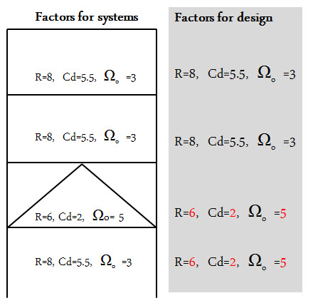 ASCE7-10 revised the way designers use the corresponding Drift amplification, Cd, and Overstrength factor, Ωo, of the Response modification factor, R. In ASCE7-05, when there is a vertical combination of different R-values, the Cd, and Ωo cannot decrease as you go down each level of a building. In ASCE7-10 (12.2.3.1), the Cd and Ωo always correspond to the R-Value as you go down. The adjacent figure illustrates the new provision to use the corresponding Cd, and Ωo with the R-value at each level.
ASCE7-10 (12.3.4.1) added a clarification for out-of-plane anchorage forces where the redundancy factor, p = 1.0. The intent of the redundancy factor was to ensure the vertical seismic-resisting system with insufficient redundancy had adequate strength. The design forces for out-of-plane wall loading are not redundancy requirements. ASCE7-10 (12.11.12) revised the out-of-plane wall anchorage force equation where the anchorage forces are reduced for shorter diaphragm spans.
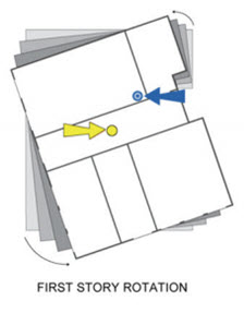 Light-frame construction structures are no longer exempt from amplification of accidental torsion in ASCE7-10 (12.8.4.3). There are many structures vulnerable to torsional effects including some “tuck under” parking buildings that are often light-frame structures. See posts titled Soft-Story Retrofits and City of San Francisco Implements Soft-Story Retrofit Ordinance for more discussion of soft-story, light-frame buildings.
This is just a brief summary of changes related to seismic design found in the 2012 IBC. What are other changes that will modify your approach to seismic design?
Our Latest Online Resource: Steel Deck Diaphragm Calculator
Although Simpson Strong-Tie is best known for our structural products: engineered structural connectors, lateral systems, fasteners and fastening systems, anchoring products and most recently, concrete repair, protection and strengthening (RPS) systems, we are continually developing new and exciting software solutions. As we’ve discussed in prior blog posts, Simpson Strong-Tie has numerous software programs and web and mobile apps available for download or online use at www.strongtie.com/software. Today, I’d like to review our recently launched web app, the Steel Deck Diaphragm Calculator. The calculator is accessible from any web browser and doesn’t require downloading or installing special software.
While the method of designing and specifying a steel deck and its attachment can vary by region, most designers are familiar with the Steel Deck Institute (SDI) and its Diaphragm Design Manual, 3rd Edition (DDM03). DDM03 presents diaphragm shear strength and stiffness equations for various steel deck profiles and commonly used attachment types (welds, power-actuated fasteners, or screws). The calculations can be quite tedious, so the SDI has developed numerous tables using these equations and placed them at the back of DDM03 for easy reference.
Since the tables in DDM03 are based solely on the fasteners and deck profiles included, determining diaphragm capacities utilizing any other proprietary fastener or deck profile fall on the designer or the proprietary product’s manufacturer. Enter Simpson Strong-Tie.
Our Steel Deck Diaphragm Calculator enables users to produce custom diaphragm tables similar to those in DDM03, generate detailed calculations using SDI equations based on project-specific inputs, as well as optimize deck fastening systems to ensure the most cost-effective design is utilized. The calculator incorporates our X-series steel decking screws, including the recently launched Strong-Drive® XL Large-Head Metal Screw, which has one of the highest capacities in the industry and in most cases, can be used as a 1-for-1 replacement of pins or 5/8 diameter puddle welds. (For additional information comparing Simpson Strong-Tie X-series and XL screws to pins or welds, review F-Q- STLDECK14.)

The app can be used with minimal required input to generate tables and project-specific calculations. A more detailed analysis can be performed by inputting parameters for up to five unique zones, including overall dimensions, diaphragm shear, joist spacing, uplift and more.
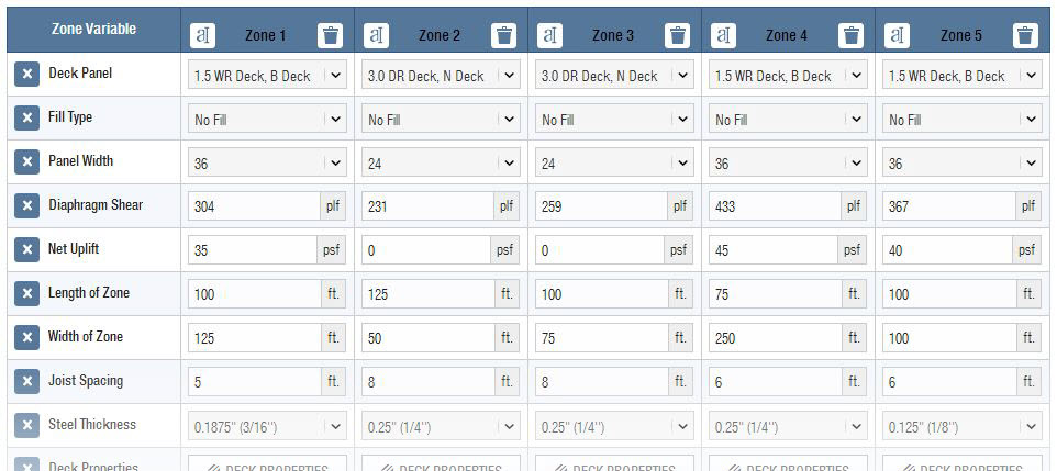
One unfortunate aspect of many web apps is that your work is typically lost once you close your web browser. I’m happy to report that the folks here in our app development group have added the ability to save and upload project files. The calculator also provides a clean PDF printout of your results while giving you the option to generate a submittal package with supporting documentation, such as code reports, product approvals and installation recommendations.
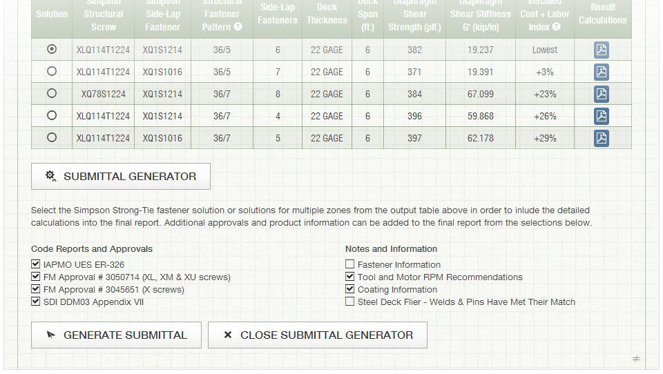
Try the revised Steel Deck Diaphragm Calculator yourself and let us know what you think. We always appreciate the feedback!
Changes Made to ACI 318 With Respect to Adhesives Anchors in Concrete: What Engineers Need to Know
For the first time, ACI 318 – 11 includes a design provision for adhesive anchors in concrete. Previously, adhesive anchors were designed according to provisions found in both ICC Evaluation Service (ICC-ES) AC308 and ACI 318 – 08. A relatively new standard, ACI 355.4, must be used to qualify adhesive anchors in concrete. This new standard, along with ACI 318 – 11, contains important changes that will affect anchor systems designed to the 2012 IBC. Not all changes are discussed here. I will only focus on what you – the engineer – should be aware of.
ACI 355.4 requires that adhesive anchors in concrete be evaluated using a bond strength (measured in terms of psi and used with the surface area of the embedded portion of the anchor) that corresponds to a long-term temperature (LTT) of 110 degrees F to account for potential elevated temperature exposure conditions. This wasn’t necessarily the case previously where, for example, the engineer could elect to use a temperature category that listed bond strength values based on a LTT of 75 degrees F. The issue here is creep.
Creep, in the world of adhesive anchors, looks at how well the anchor can resist load without too much axial displacement over a period of not minutes, not hours, not even years but decades. As a general rule, it’s no surprise that creep worsens as the temperature rises for almost any material. In our case, the bond strength is effectively reduced. Most adhesives, if not all, currently list bond strength values that correspond to a LTT of 110 degrees F. Make sure to select the temperature category that meets this minimum requirement. Some adhesives will experience a reduction in bond strength at an LTT of 110 degrees F, some won’t.
What about applications involving short-term-only loading? Is creep still relevant? Generally, you’ll find that adhesive anchors negatively impacted by the higher LTT requirement will gain back much of their load for seismic/wind-only load applications. So creep becomes irrelevant.
While adhesive anchors used solely for the purpose of resisting short-term loads will remain largely unaffected by this code change, significant changes have been made to the design and installation of adhesive anchors when used for sustained loading applications (e.g. dead load, live load, etc.).
First, the bond strength must be reduced by a factor of 0.55 as compared to 0.75 under the previous code (following ICC-ES AC308). New to the code, section D.9.2.2 of ACI 318 App. D requires that adhesive anchors used for resisting sustained loads be installed by someone who has taken the Adhesive Anchor Installation Certification (AAIC) program. The installer must show proof that he/she is certified by passing both a written and performance examination. Installing adhesive overhead requires some skill. So it’s no surprise that the installer must satisfactorily demonstrate proficiency by blindly installing adhesive overhead into an inverted test tube that will later be cut in half and graded for the presence of voids. Figure 1 shows no voids, so the installer passed.
Arguably, with AAIC, there’s an added cost to using adhesives for anchorage designed for sustained loading. However, for sustained loading applications best suited for adhesive anchors it should come as peace of mind to the engineer, owner, contractor and other parties involved with the construction project that a certified installer has been employed to ensure that the adhesive anchor has been installed in accordance with the manufacturer’s printed installation instructions.
While the engineer should be aware of the above limitations placed on adhesive anchors, by no means should it hamper their design. There are several options available to the engineer. Table 1 compares the tensile design strength of three common types of anchors – two adhesives, two mechanical anchors (one screw and one expansion type) – determined using the new design provision ACI 318 -11. While the creep test results show a reduced capacity for adhesive A, it does show a significant increase in load for seismic-only applications because , as we discussed earlier, creep is no longer an issue. Some adhesives, like adhesive B, will do well under the creep test (at an elevated LTT of 110 degrees F), so any capacity increase for seismic-only applications will be small.
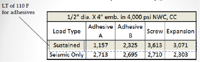
What three important points can we glean from Table 1? First, all things being equal, mechanical anchors will typically achieve higher “code values” for sustained loading applications relative to adhesives. Second, mechanical anchors are easier to install overhead. Third, AAIC is not required for mechanical anchors. While these reasons support using mechanical anchors for overhead anchorage, doing so is nothing new. The bulk of overhead attachments have almost always been made with mechanical anchors mainly because it’s just easier to do it that way.
Perhaps up to 95% of adhesives are used to secure rebar to concrete – we’ll call them rebar dowels. Like any anchor, rebar dowels can be used to resist seismic and/or sustained loads. While the exact breakdown is hard to determine, arguably, the bulk of rebar dowels in the west coast are found in seismic retrofits and renovations used to thicken walls, tie-in new concrete shear walls, connect new drag struts, strengthen existing concrete elements, etc., all for the purpose of strengthening the lateral capacity of the existing structure to withstand greater earthquake and/or wind loads. These typically won’t require a CAAI, but it might if it’s a school or hospital project that requires overhead or horizontal anchors. Some rebar dowels are used for enlarging footings to withstand greater dead and live loads, so these would require a CAAI. Remember: the bond strength can be lower than expected for sustained loading applications, so you may want to use an adhesive that does well at a LTT of 110 degrees F if that’s what your design requires.
One new benefit of ACI 318 is that the engineer can now design adhesive anchors to go into lightweight concrete using the factors found in section D.3.6.
One significant change engineers should include in their specification is that the concrete must be aged at least 21 days before installing an adhesive. Previously, the industry standard was to wait seven days. For additional information regarding adhesives installed into younger normal-weight concrete, read the following Simpson Strong-Tie engineering letter: http://www.strongtie.com/ftp/letters/generic/L-A-ADHGRNCON14.pdf
What are you experiencing in the design of your anchors in your jurisdictions? Leave a comment down below because we would like to know.