This week’s blog was written by Branch Engineer Randy Shackelford, P.E., who has been an engineer for the Simpson Strong-Tie Southeast Region since 1994. He is an active member of several influential committees, including the AISI Committee on Framing Standards, the American Wood Council Wood Design Standards Committee, and the Federal Alliance for Safe Homes Technical Advisory Committee. He is vice-president and member of the Board of Directors of the National Storm Shelter Association. Randy has been a guest speaker at numerous outside seminars and workshops as a connector and high wind expert. Here is Randy’s post:
In my last blog post, I gave an overview of FLASH, the Federal Alliance for Safe Homes, and how Simpson Strong-Tie partners with them. Last November, FLASH held their Annual Conference. The theme of this past meeting was “15 Years of Stronger Homes and Safer Families,” and it was one of their best conferences yet.Continue Reading
When Simpson Strong-Tie began supporting the use of iPads by employees, it was about the same time my Blackberry contract was expiring, so I decided to go all-in with Apple® and get an iPhone® 4s and an iPad®. Since mobile devices will not replace the heavy lifting required from most engineers’ computers, I wanted to find some apps that complemented my PC use and made me more efficient when I was away from my desk. After reading reviews and trying out a few, I eventually came up with a list of apps that I recommend. None were developed for engineers, but they are the ones I use most often. Let me know what you think of these or any of your favorites that I missed.
DropBoxGoogle Drive
1. File Sharing Apps: My initial search was for a way to share files between my Apple devices and my PC. Since there is limited space in the free cloud services, I use two: Dropbox (free) for work files and Google Drive (free) for home files. Install the apps on your mobile devices and the software on your computers, create and log into your account, and you are ready to access/modify/share any of these files on any device. Both of these apps are seamlessly integrated into many other apps.
Notability
2. Organization: I am not the most organized person, so I wanted an app that would help me keep track of my many notes. After trying a few different ones, I settled on Notability ($3). I can take handwritten or typed notes, insert a picture of things like a jobsite photo or a paper handout, draw a sketch, or even insert an audio recording. Best of all, I can organize the notes in folders within the app and also back them up as PDF files to Dropbox.
SlideShark
3. Presentations: I regularly give PowerPoint presentations, so I started using an app called SlideShark (free) and got hooked. It is simple and remains true to the look of the original PowerPoint program. With the current version, I can access files on my DropBox account, play embedded videos, and use my iPhone as a remote when my iPad is connected to a projector. Although I still present with my trusty laptop most of the time, SlideShark is also great for practicing a presentation on a mobile device anywhere you find yourself with a few spare minutes.
MyScript Calculator
4. Calculator: I was shocked to find that my iPad didn’t have a built-in calculator app. I tried a few free ones, but never really liked them. Then MyScript Calculator (free) came out last year, which solves handwritten equations like the one shown in the icon. Now I look for reasons to use it. It won’t ever replace my TI-85, but I am not sure I want it to.
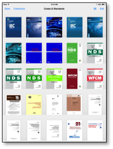
iBooksiBooks Shelf
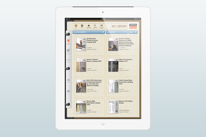
5. Reference Guides: I like the idea of having electronic versions of my codes and referenced standards all saved in my iPad. Some of the PDF files I purchased allow me to save them in iBooks (free); others shown in the screenshot are just covers. On a side note, ICC has all of their codes online, broken into sections (as opposed to a single PDF). It’s great for sending links of specific code language to people that don’t own the code.
GoodReader
6. Editor Apps: There are tons of PDF editing apps out there. I asked around to see what other engineers use and decided on GoodReader ($5). I have been pretty happy with it, mostly using it to mark up PDF files I am reviewing.
PhotoSynth
7. Photos: When out on a jobsite, there is no better way to capture information than with a picture. But when everything can’t fit inside the viewfinder, PhotoSynth (free) is a great tool to capture the surroundings. Immersive 360° images can be posted online, shared, or viewed within the app. Here are links to a couple of mine: Hurricane Sandy, Columbus Test Lab.
SnapSeed
8. Photo Editing: While on the topic of photos, I use Snapseed (free) whenever I need to edit them. It is simple and intuitive, but powerful enough to get the job done.
Scanner Pro
9. Scanner Pro ($3) turns your camera into a scanner. Take a picture of a paper document, then locate the corners of the paper within the app and turn it into a PDF file that scales and stretches it to look like a scan instead of a snapshot.
PaperSketchbook Express
10. Sketch Apps: My favorite apps for sketching a new connector idea, illustrating a concept or just doodling, are Paper (free) and SketchBook Express (free). Paper is more free-form and natural, while SketchBook has more tools and provides more precise control. They are free, so give them both a try.
*Apple, the Apple logo, iPhone and iPad are trademarks of Apple Inc., registered in the U.S. and other countries.*
A few days ago, I was speaking to a customer about an application using nail substitutions for a joist hanger installation. Her questions come up often, so I thought I would dedicate a blog post to some of the resources available that cover the use of different nails in connectors.
Designers and builders often wish to use different fasteners than the catalog specifies. The application could require short nails that don’t penetrate through the back of a ledger or they want to use screws or sinker nails for easier installation. The Wood Connectors Catalog provides multiple options for alternate nailing for face mount hangers and straight straps on page 24.
The load adjustments for alternate fasteners cover substitutions from a common diameter of 16d to a 10d, or a 10d to an 8d. Multiple different replacement lengths are also covered, with reduction factors ranging from 0.64 to 1.0.
It is important to remember that double shear hangers require 3” minimum joist nails. Short nails installed at an angle in double shear hangers will not have adequate penetration into the header.
Pneumatic nail guns used for connector installation are commonly referred to as positive placement nail guns. These tools either have a nose piece that locates connector hole, or the nail itself protrudes from the tool so that the installer can line the nail up with the hole. Most positive placement tools do not accept nails longer than 2½”, so framers using these tools will want to use 1½” or 2½” nails. To accommodate installers using pneumatic nails, we have a technical bulletin T-PNUEMATIC. This bulletin provides adjustment factors for many of our most common embedded holdowns, post caps and bases, hangers and twist straps.
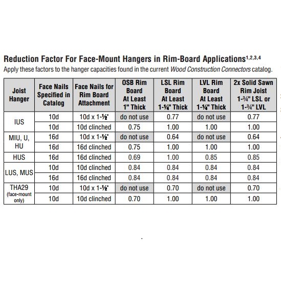
The question of nail size also comes up when attaching hangers to rim board, which can range from 1” to 1¾”. The adjustment factors in C-2013 don’t necessarily apply with rim board, since the material may be thinner the length of the nails used. We also have a technical bulletin for that application – T-RIMBDHGR.
Rim Board Reduction Factors
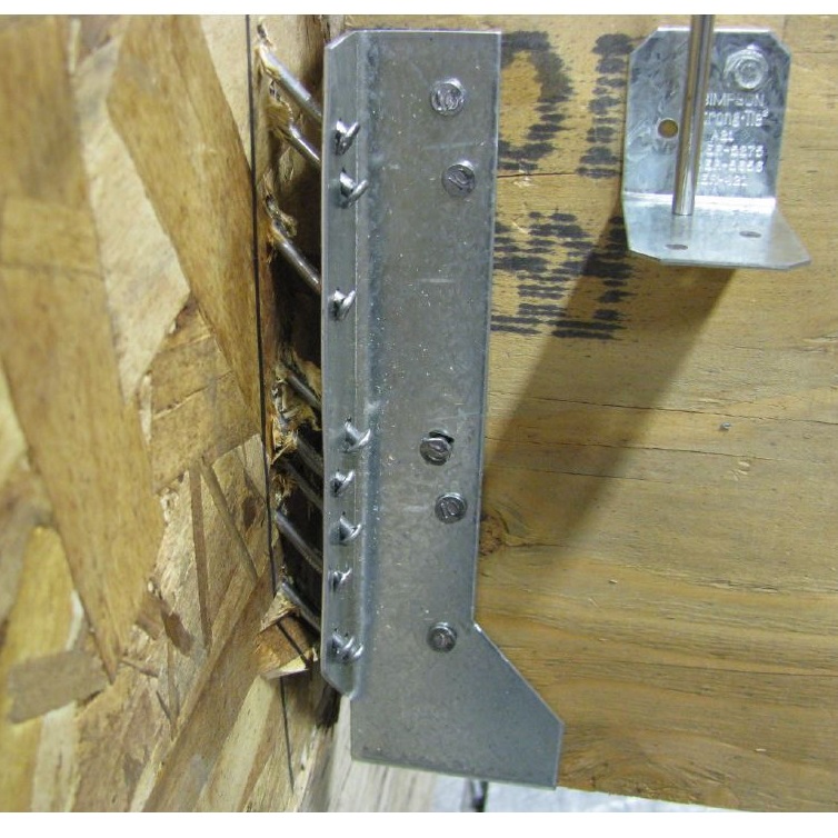
Several of the reduction factors are the same as those in the catalog. Testing of hangers with 10dx1½ nails on 1” OSB or 1¼” LVL did not do as well, however. We observed that once the nails withdrew a little bit under load, they quickly lost capacity. For that reason, we recommend full length 10d or 16d nails on those materials.
Rim board failure
Understanding that alternate fasteners are available for many connectors can help you pick the right fastener for you application. When you specify a connector, it is important to also specify the fasteners you require to achieve your design load.
Happy New Year! This week’s blog was written by Branch Engineer Randy Shackelford, P.E., who has been a guest speaker at numerous outside seminars and workshops as a connector and high wind expert.
I attended a CFSEI and Steel Framing Alliance webinar last week entitled Specifying Cold-Formed Steel: Finding and Avoiding Pitfalls in Structural General Notes and Architectural Specifications. The presenter was Don Allen, P.E., from DSi Engineering, LLC, and he focused on issues specifically related to design and specification of cold-formed steel (CFS) in contract documents.
While the title of this blog post might remind you of the tasty turkey dinner you enjoyed on Thanksgiving, it’s actually a question regarding a shear wall component’s effect on performance. What type of fastener do you use to attach wood structural panel sheathing to cold-formed steel (CFS) framing, and what is the effect on a shear wall assembly?
Structural sheathing is most commonly attached to CFS framing with self-piercing or self-drilling tapping screws, power driven pins, and adhesives.
The AISI North American Standard for Cold-Formed Steel Framing – Lateral Design standard (S213) specifies using either #8 or #10 self-tapping screws (depending on the assembly) that comply with ASTM C1513, and have a minimum head diameter of 0.285” or 0.333”, respectively.
It’s worth noting that you cannot verify ASTM C1513 compliance by simple inspection. While screw dimensions are easy to measure, other features such as hardness, ductility, torsional strength, drill drive, and thread tapping cannot be evaluated in the field or by visual inspection. It’s prudent that a Designer and jurisdiction expect a screw manufacturer to validate its product’s compliance with ASTM C1513. This can be done through test reports by an accredited test lab and evaluation data, or by an evaluation report published by an ANSI-accredited product certification entity such as ICC-ES or IAPMO UES.Continue Reading
Wishing you and your loved ones a Happy Thanksgiving. Our U.S. offices are closed Thursday and Friday, November 28-29 for the holiday. Talk to you next week!
The Wei-Wen Yu Center for Cold-Formed Steel Structures has issued a Call for Papers for the 22nd International Conference on Cold-Formed Steel (CFS) Structures, to be held Nov. 5-6 in St. Louis, MO. The goal of the conference is to enable sharing of state-of-the-art information pertaining to CFS design.
Both engineering researchers and practitioners have provided valuable contributions to the conference. Past proceedings are available online.
Researchers and practitioners are encouraged to submit abstracts for consideration by the conference steering committee. Application-oriented topics highlighting innovations in CFS applications are strongly encouraged. The deadline is Dec. 31. Abstracts may be submitted by e-mail to ccfss@mst.edu.
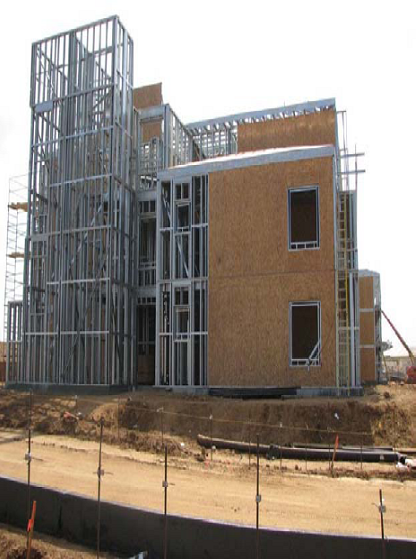
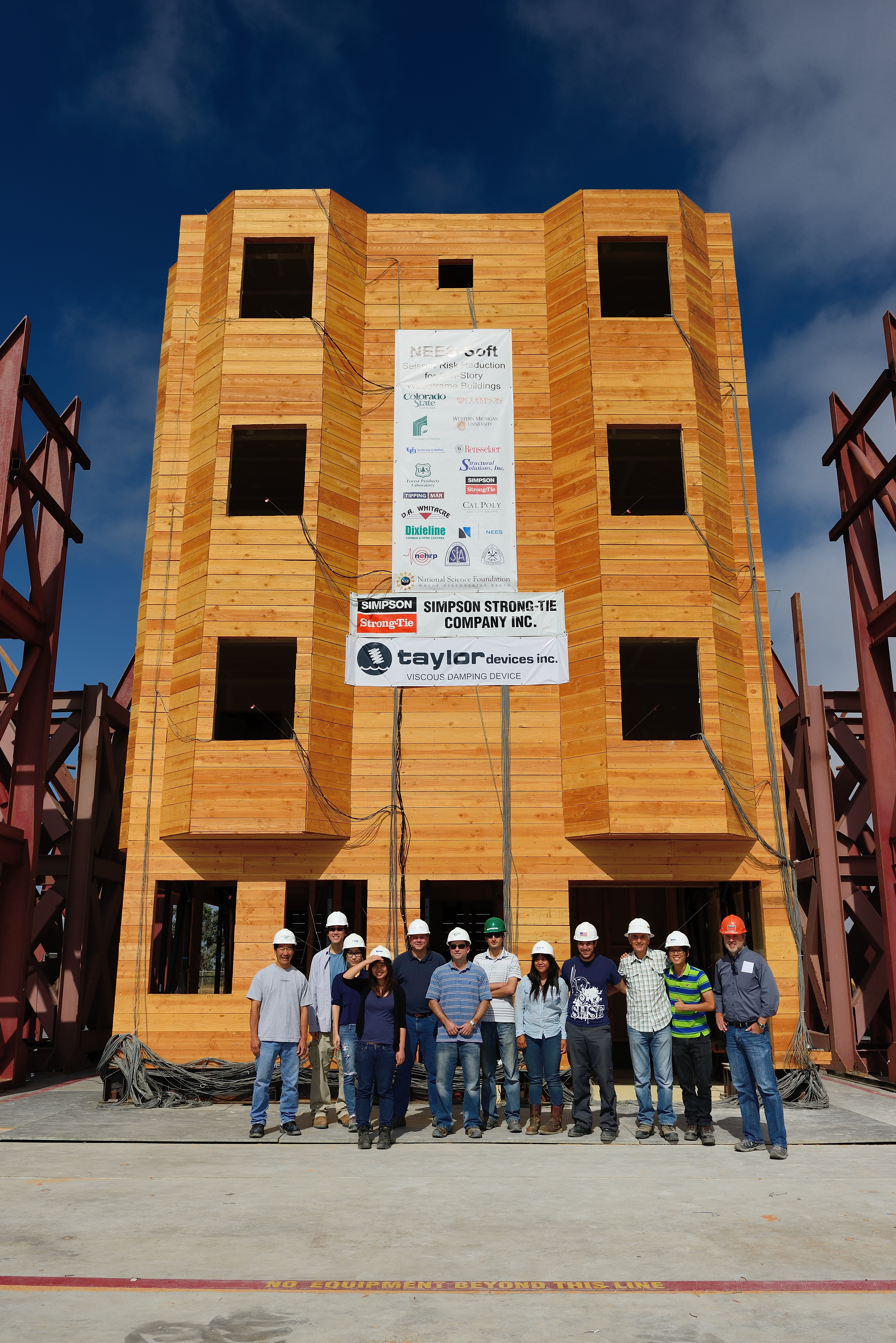
NOVA,the highest rated science series on television, recently aired a segment on the Colorado State University-led NEES-Soft project that tested Simpson Strong-Tie® Strong Frame® special moment frames as a seismic retrofit solution for soft-story buildings. Simpson Strong-Tie and our special moment frame were prominently featured in the clip. You can watch the entire “Making Stuff Safer” episode on PBS here.
A couple of years ago, my brother-in-law asked if I could stop by the swim club where he is a board member. He was overseeing a construction project to upgrade the buildings and patio covers, which involved dry-rot repairs and the addition of Simpson Strong-Tie® connectors to create a continuous load path. He wanted me to meet with the contractor and make some suggestions for alternate connectors. The as-built conditions didn’t work for the specified connectors at a few locations, and there were some spots where he thought the connectors were “ugly.” I’m probably in the minority on this, but I think shiny galvanized steel connectors are just beautiful. So the “ugly” comment stung a little bit.
Once I got over my hurt feelings, I grabbed my Wood Construction Connectors catalog, aDeck Connection and Fastening Guide, and a few other fliers and technical bulletins that I thought might be helpful and drove across town to meet them. With literature in hand, we were able to come up with ways to work around the more difficult areas, and also select some more aesthetically pleasing architectural connectors at prominent locations. I thought we were done, and then the contractor had a few more questions on anchoring that I needed an Anchoring and Fastening Systems Catalog to look up some information on – and I didn’t have one! I managed to muddle through with my smartphone and find the information online, but couldn’t help but think that there had to be a better way to access design information when you are out of the office.
The better way has arrived in the latest version of the Simpson Strong-Tie® Literature Library mobile app. It was just launched this month and is much more comprehensive than the first version. There are several new features that I wanted to highlight for you.
We use cookies on this site to enhance your user experience. By clicking "I AGREE" below, you are giving your consent for us to set cookies. Privacy PolicyI AGREE
Privacy & Cookies Policy
Privacy Overview
This website uses cookies to improve your experience while you navigate through the website. Out of these cookies, the cookies that are categorized as necessary are stored on your browser as they are essential for the working of basic functionalities of the website. We also use third-party cookies that help us analyze and understand how you use this website. These cookies will be stored in your browser only with your consent. You also have the option to opt-out of these cookies. But opting out of some of these cookies may have an effect on your browsing experience.
Necessary cookies are absolutely essential for the website to function properly. This category only includes cookies that ensures basic functionalities and security features of the website. These cookies do not store any personal information.
Any cookies that may not be particularly necessary for the website to function and is used specifically to collect user personal data via analytics, ads, other embedded contents are termed as non-necessary cookies. It is mandatory to procure user consent prior to running these cookies on your website.