Do you ever get so busy that you can’t keep up with the structural engineer training opportunities that are available? We have previously shared online resources and webinars that are available to structural engineers, but did you know that you can take advantage of Simpson Strong-Tie regional training centers that offer complimentary workshops and classes about proper specification, product installation and inspection of connectors and structural systems? Here are some tips on staying current with your training.
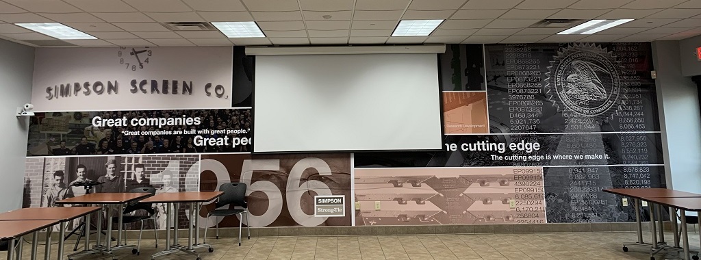
Simpson Strong-Tie training courses and webinars are focused on improving building standards and the overall safety of structures. With eight training centers across North America, Simpson Strong-Tie provides hundreds of complimentary classes to engineers, architects, builders and code officials each year. In fact, we have trained more than 24,000 participants online and in-person in 2016 alone.
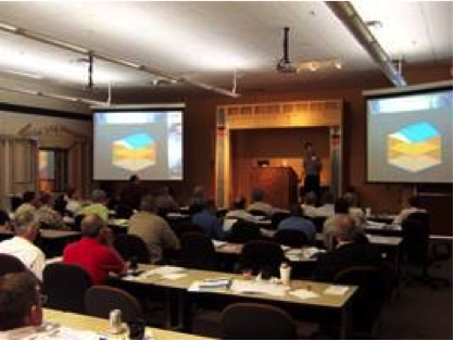
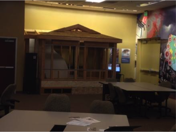
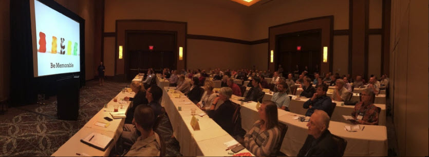
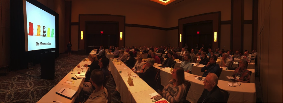
“The workshops are very interactive,” explained Charlie Roesset, Director of Training for Simpson Strong-Tie. “Depending on the course, students may have the opportunity to view product samples or take part in product testing and installations.”
Tip #1 Make Training Offerings Work for You
 If you specialize in a specific discipline, look for courses that are targeted to your area of interest or expertise. Simpson Strong-Tie courses include a broad range of topics from anchor system installation and engineered wood frame construction to seismic and high-wind design. We also incorporate the latest building-code updates and industry trends into our training curriculum. No matter where you are in your professional career, we offer a course that’s right for you. There are introductory courses as well as more advanced workshops for repeat and seasoned attendees.
Training participants receive a certificate of attendance with professional development hours (PDHs) at the end of each workshop, and may earn continuing education units (CEUs) and/or learning units (LUs) by completing additional requirements. Simpson Strong-Tie is a registered education provider with a number of industry organizations and associations including CSI, BIA, ACIA, AIBD, ICC, AIA* and IACET**.
Tip #2 Find Trainings That Are Current
Do your research to find workshops and online courses that are regularly updated to reflect changes within the industry. For example, we have regular trainings that focus on the new seismic retrofit ordinances in various municipalities on the West Coast (such as Los Angeles’ Soft-Story Retrofit Ordinance) and others on high-wind design and construction in the Southeast. Our trainings are tailored to your design needs based on your practice’s location.
Full-day workshops typically run from 8:00 a.m. to 4:00 p.m. Classes are often tailored toward specific audiences types to ensure that the training is appropriate and effective. Many courses are team-taught by registered engineers to provide in-depth technical expertise in the subject matter. While much of the instruction is technical in nature, many real-life examples and hands-on demonstrations are provided to help all attendees fully understand the material presented.
Tip #3 Hear What Other Structural Engineers Have to Say

It is always a good sign when others in your field have good things to say about the courses they have taken. Below are some comments past participants have said about our training offerings:
Fred B., S.E., an engineer from Las Vegas, NV, has been a regular attendee of Simpson Strong-Tie workshops. He says the training keeps him informed of topics relevant to his industry and is a great way to keep up with his professional development hours. “Some of the courses offered by other groups are just not that interesting and they can be quite expensive. Simpson programs are interesting, hands-on and free. It’s the whole package.”
Bob N., an engineer from Richmond, VA, wrote, “Keep up the good work; I have found your seminars to be well done, pertinent, and useful. We also specify a lot of your products because of the training and the fact that you have an excellent product line.”
Kathy P., an engineer from Somerville, TX, shares: “You guys are so great! You teach well and keep it interesting. . . . . You support the industry to the benefit of everyone, not just your bottom line, and you make educational credits cost effective. Thank you, thank you, thank you!”
Sign up for a workshop and find out more about Simpson Strong-Tie training programs, including our latest online courses, by visiting www.strongtie.com/workshops.
* Simpson Strong-Tie is registered with the American Institute of Architects, Continuing Education System (AIA CES) as a provider of AIA Learning Units (AIA LUs).
** Simpson Strong-Tie is accredited by the International Association for Continuing Education and Training (IACET) and is authorized to issue the IACET CEU.
Written by Minara El-Rahman in collaboration with the Simpson Strong-Tie Training Department.