Building Code Update: 2018 IBC to Reference ASCE 7-16

In early December, ICC posted the preliminary results of the Group B Online Governmental Consensus Vote, which included structural changes to the IBC, IEBC and IRC. ICC reports that there were more than 162,000 votes cast by eligible Voting Members during the three-week online voting period.

One subject of interest to building Designers, builders and some building-material suppliers was the disposition of a group of code changes that adopted ASCE 7-16 as the reference standard on loads for the IBC and IRC, and changed other parts of the IBC and IRC to reflect that.

The most controversial part of adopting the new ASCE 7-16 standard was its increase in roof component and cladding loads. The higher pressure coefficients in some cases raised the concern that the cost of roofing, roofing materials and roof repairs would be increased. Other items that raised some opposition were the new chapter on tsunami loads and the increase in deck and balcony live loads from 40 psf to 60 psf.

Despite these concerns, ICC members voted to approve the code change that adopted ASCE 7-16 as the reference for loads in the 2018 IBC, IRC and IEBC.

Along with that specific change, several other related changes were approved to correlate the IBC with adoption of ASCE 7-16. These included changes to Section 1604, General Design Requirements; adding in a new Section 1615 on Tsunami Design Requirements; modifications to Section 1613 so that seismic design requirements match ASCE 7-16; and deletion of Section 1609.6, Alternate All-Heights Method for wind design. On this last item, the argument was that since ASCE 7 now includes a simplified wind load design method, a competing method is not needed in the IBC.

Interestingly, a change to remove Strength Design and Allowable Stress Design load combinations from the IBC, which was approved by the IBC Structural Committee, was overturned and denied by the ICC Member voters. So those will remain in the IBC.

For the IRC, even though ASCE 7-16 will be shown as the referenced load standard, most changes to the actual code language relating to the new standard were denied. Items that were specifically denied included adoption of ASCE 7-16 wind speed maps, adoption of ASCE 7-16 roof pressure loading, and adoption of the new higher deck and balcony live loads. So the result is that the IBC and IRC will again be inconsistent with each other regarding wind design. On the other hand, the new USGS/NEHRP Seismic Design Maps were approved.

Future Code Corner articles will address other changes approved for the 2018 IBC and IRC.


3 Hot Tips for Structural Engineers Who Want to Earn Education Credits and Stay Sharp

Do you ever get so busy that you can’t keep up with the structural engineer training opportunities that are available? We have previously shared online resources and webinars that are available to structural engineers, but did you know that you can take advantage of Simpson Strong-Tie regional training centers that offer complimentary workshops and classes about proper specification, product installation and inspection of connectors and structural systems? Here are some tips on staying current with your training.

Simpson Strong-Tie training courses and webinars are focused on improving building standards and the overall safety of structures. With eight training centers across North America, Simpson Strong-Tie provides hundreds of complimentary classes to engineers, architects, builders and code officials each year. In fact, we have trained more than 24,000 participants online and in-person in 2016 alone.

“The workshops are very interactive,” explained Charlie Roesset, Director of Training for Simpson Strong-Tie. “Depending on the course, students may have the opportunity to view product samples or take part in product testing and installations.”

Tip #1 Make Training Offerings Work for You

If you specialize in a specific discipline, look for courses that are targeted to your area of interest or expertise. Simpson Strong-Tie courses include a broad range of topics from anchor system installation and engineered wood frame construction to seismic and high-wind design. We also incorporate the latest building-code updates and industry trends into our training curriculum. No matter where you are in your professional career, we offer a course that’s right for you. There are introductory courses as well as more advanced workshops for repeat and seasoned attendees.

Training participants receive a certificate of attendance with professional development hours (PDHs) at the end of each workshop, and may earn continuing education units (CEUs) and/or learning units (LUs) by completing additional requirements. Simpson Strong-Tie is a registered education provider with a number of industry organizations and associations including CSI, BIA, ACIA, AIBD, ICC, AIA* and IACET**.

Tip #2 Find Trainings That Are Current

Do your research to find workshops and online courses that are regularly updated to reflect changes within the industry. For example, we have regular trainings that focus on the new seismic retrofit ordinances in various municipalities on the West Coast (such as Los Angeles’ Soft-Story Retrofit Ordinance) and others on high-wind design and construction in the Southeast. Our trainings are tailored to your design needs based on your practice’s location.

Full-day workshops typically run from 8:00 a.m. to 4:00 p.m. Classes are often tailored toward specific audiences types to ensure that the training is appropriate and effective. Many courses are team-taught by registered engineers to provide in-depth technical expertise in the subject matter. While much of the instruction is technical in nature, many real-life examples and hands-on demonstrations are provided to help all attendees fully understand the material presented.

Tip #3 Hear What Other Structural Engineers Have to Say

Training

It is always a good sign when others in your field have good things to say about the courses they have taken. Below are some comments past participants have said about our training offerings:

Fred B., S.E., an engineer from Las Vegas, NV, has been a regular attendee of Simpson Strong-Tie workshops. He says the training keeps him informed of topics relevant to his industry and is a great way to keep up with his professional development hours. “Some of the courses offered by other groups are just not that interesting and they can be quite expensive. Simpson programs are interesting, hands-on and free. It’s the whole package.”

Bob N., an engineer from Richmond, VA, wrote, “Keep up the good work; I have found your seminars to be well done, pertinent, and useful. We also specify a lot of your products because of the training and the fact that you have an excellent product line.”

Kathy P., an engineer from Somerville, TX, shares: “You guys are so great! You teach well and keep it interesting. . . . . You support the industry to the benefit of everyone, not just your bottom line, and you make educational credits cost effective. Thank you, thank you, thank you!”

Sign up for a workshop and find out more about Simpson Strong-Tie training programs, including our latest online courses, by visiting www.strongtie.com/workshops.

* Simpson Strong-Tie is registered with the American Institute of Architects, Continuing Education System (AIA CES) as a provider of AIA Learning Units (AIA LUs).

** Simpson Strong-Tie is accredited by the International Association for Continuing Education and Training (IACET) and is authorized to issue the IACET CEU.

Written by Minara El-Rahman in collaboration with the Simpson Strong-Tie Training Department.


Decrypting Cold-Formed Steel Connection Design

As published in STRUCTURE magazine, September 2016. Written by Randy Daudet, P.E., S.E., Product Manager at Simpson Strong-Tie.  Re-posted with permission. 

One of the world’s greatest unsolved mysteries of our time lies in a courtyard outside of the Central Intelligence Agency (CIA) headquarters in Langley, Virginia. It’s a sculpture called Kryptos, and although it’s been partially solved, it contains an inscription that has puzzled the most renowned cryptanalysts since being erected in 1990. Meanwhile, in another part of the DC Beltway about 15 miles to the southeast, another great mystery is being deciphered at the American and Iron Institute (AISI) headquarters.Continue Reading

SEAOSC Safer Cities Survey Results: How Are We Building Strength and Transparency in Our Communities?

Back in January, employees at Simpson were given the opportunity to learn more about the 401K retirement and investment plan. The big takeaways from my training session were a) save as much as you can as early as you can in life and b) use asset allocation to diversify your portfolio and avoid too much risk. Now, I’m not a big risk taker in general, so I dutifully picked a good blend of stocks and bonds with a range of low to high risk. It seems like a pretty sound strategy and it made me think of all the other ways I tend to minimize risk in my life. When I head to a restaurant, for example, I almost instinctively look for the county health grade sign in the window. When my husband and I went to go buy a new family car a couple years ago, I remember searching the National Highway Traffic Safety Administration (NHTSA) website for crash test ratings. Even when I’m doing something as mundane as having a snack, I will invariably flip over the Twinkie package to see just how many grams of fat are lurking inside (almost 5 per serving!). For all the rankings and information available to the general public for restaurants, cars and snacks, there isn’t much, if any, information to help us know if we’re minimizing our risk for one of the most common activities we do almost every day: walking into a building.

Risk level knob positioned on medium position, white background and orange light. 3D illustration concept for business security management.


Now before you accuse me of being overly dramatic about such a trivial activity, here’s some food for thought: research has shown that Americans spend approximately 90% of their day inside a building. That’s over 21 hours a day! Have you ever once thought to yourself, “I wonder if this building is safe? Would this building be able to withstand an earthquake or high wind event?” Or how about even taking a step back and asking, “Are there any buildings that are already known to be potentially vulnerable or unsafe, and has my city done anything to identify them?” Unfortunately, that kind of information about a city’s building stock is not usually readily available, but some in the community, including structural engineers, are working to change that.

Los Angeles skyline on a partly cloudy day with a row of palm trees in the foreground.


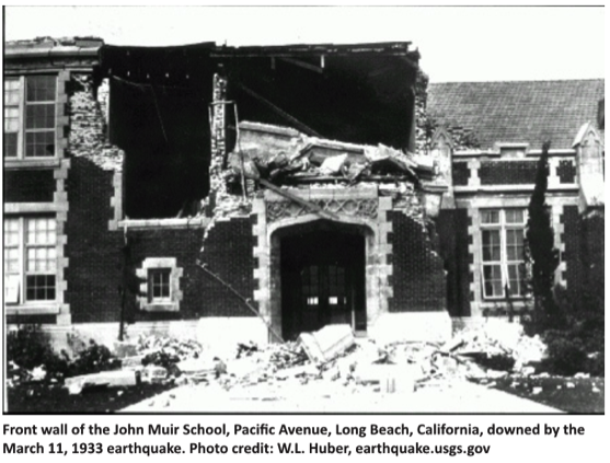
The charge is being led in California, a.k.a. Earthquake Country, where structural engineers are teaming up with cities to help identify buildings with known seismic vulnerabilities and provide input on seismic retrofit ordinances. Structural engineers have learned quite a bit about how buildings behave through observing building performance after major earthquakes, and building codes have been revised to address issues accordingly. However, according to the US Green Building Council, “…the annual replacement rate of buildings (the percent of the total building stock newly constructed or majorly renovated each year) has historically been about 2%, and during the economic recession and subsequent years, it’s been much lower.” This means that there are a lot of older buildings out there that have not been built to current building codes and were not designed with modern engineering knowledge.

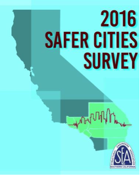
Several cities in California have enacted mandatory seismic retrofit ordinances that require the strengthening of some types of known vulnerable buildings, but no state or nation-wide program currently exists. The Structural Engineers Association of Southern California (SEAOSC) recently decided to launch a study of which jurisdictions in the southern California region have started to take the steps necessary to enact critical building ordinances. According to SEAOSC President Jeff Ellis, S.E., “In order to develop an effective strategy to improve the safety and resilience of our communities, it is critical to benchmark building performance policies currently in place. For southern California, this benchmarking includes recognizing which building types are most vulnerable to collapse in earthquakes, and understanding whether or not there are programs in place to decrease risk and improve recovery time.” These results were presented in SEAOSC’s Safer Cities Survey, in partnership with the Dr. Lucy Jones Center for Science and Society and sponsored by Simpson Strong-Tie.

safer-cities-ca

This groundbreaking report is the first comprehensive look at what critical policies have been implemented in the region of the United States with the highest risk of earthquake damage. According to the Los Angeles Times, the survey “found that most local governments in the region have done nothing to mandate retrofits of important building types known to be at risk, such as concrete and wooden apartment buildings.”

The Safer Cities Survey highlights how the high population density of the SoCal region coupled with the numerous earthquake faults and aging buildings is an issue that needs to be addressed by all jurisdictions as soon as possible. An excerpt from the survey covers in detail why this issue is so important:

No building code is retroactive; a building is as strong as the building code that was in place when the building was built. When an earthquake in one location exposes a weakness in a type of building, the code is changed to prevent further construction of buildings with that weakness, but it does not make those buildings in other locations disappear. For example, in Los Angeles, the strongest earthquake shaking has only been experienced in the northern parts of the San Fernando Valley in 1971 and 1994 (Jones, 2015). In San Bernardino, a city near the intersection of the two most active faults in southern California where some of the strongest shaking is expected, the last time strong shaking was experienced was in 1899. Most buildings in southern California have only experienced relatively low levels of shaking and many hidden (and not so hidden) vulnerabilities await discovery in the next earthquake.

 The prevalence of the older, seismically vulnerable buildings varies across southern California. Some new communities, incorporated in the last twenty years, may have no vulnerable buildings at all. Much of Los Angeles County and the central areas of the other counties may have very old buildings in their original downtown that could be very dangerous in an earthquake, surrounded by other seismically vulnerable buildings constructed in the building booms of the 1950s and 1960s. Building codes do have provisions to require upgrading of the building structure when a building undergoes a significant alteration or when the use of it changes significantly (e.g., a warehouse gets converted to office or living space). Seismic upgrades can require changes to the fundamental structure of the building. Significantly for a city, many buildings never undergo a change that would trigger an upgrade. Consequently, known vulnerable buildings exist in many cities, waiting to kill or injure citizens, pose risks to neighboring buildings, and increase recovery time when a nearby earthquake strikes.

1994-northridge

The survey also serves as a valuable reference in being able to identify and understand what the known vulnerable buildings types are:

  1. Unreinforced masonry buildings: brick or masonry block buildings with no internal steel reinforcement — susceptible to collapse
  2. Wood-frame buildings with raised foundations: single-family homes not properly anchored to the foundation and/or built with a crawl space under the first floor — possible collapse of crawl space cripple walls or sliding off foundation
  3. Tilt-up concrete buildings: concrete walls connected to a wood roof — possible roof-to-wall connection failures leading to roof collapse
  4. Non-ductile reinforced concrete buildings: concrete buildings with insufficient steel reinforcement — susceptible to cracking and damage
  5. Soft first-story buildings: buildings with large openings in the first floor walls, typically for a garage — susceptible to collapse of the first story
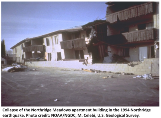
  6. Pre-1994 steel moment frame buildings: steel frame buildings built before the 1994 Northridge earthquake with connections — susceptible to cracking leading to potential collapse

1933-earthquake-shot

Along with the comprehensive list of potentially dangerous buildings, the survey also offers key recommendations on how cities can directly address these hazards and reduce potential risks due to earthquakes. As a good starting point, the survey recommends having “…an active or planned program to assess the building inventory to gauge the number and locations of potentially vulnerable buildings…is one of the first steps in developing appropriate and prioritized risk mitigation and resilience strategies.

Economic costs can be substantial for businesses whose buildings have been affected by an earthquake. After a major seismic event, a structure needs to be cleared by the building department as safe before it can be reoccupied, and it will generally receive a green (safe), yellow (moderately damaged) or red (dangerous) tag.  A typical yellow-tagged building could take up to two months to be inspected, repaired and then cleared, meaning an enormous absence of income for businesses. The survey offers a strategy for getting businesses up and running quickly after an earthquake, in order to minimize such losses. The Safer Cities Survey recommends that cities adopt a “Back-to-Business” or “Building Re-Occupancy” program, which would “create partnerships between private parties and the City to allow rapid review of buildings in concert with City safety assessments…Back-to-Business programs…[allow] private parties to activate pre-qualified assessment teams, who became familiar with specific buildings to shorten evaluation time [and] support city inspections.

oes-inspectors-program

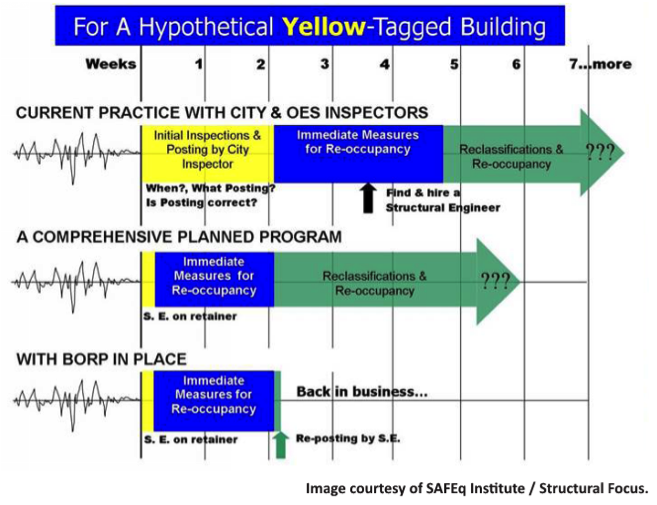
Basically, a program like this would allow a property owner to work with a structural engineer before an earthquake occurs. This way, the engineer is familiar with the building’s layout and potential risks, and can plan for addressing any potential damage. Having a program like this in place can dramatically shorten the recovery time for a business, from two months down to perhaps two weeks. Several cities have already adopted these types of programs, including San Francisco and Glendale, and it showed up as a component of Los Angeles’ Resilience by Design report.

Ultimately, the survey found that only a handful of cities have adopted any retrofit ordinance, but many cities indicated they were interested in learning more about how they could get started on the process. As a result, SEAOSC has launched a Safer Cities Advisory Program, which offers expert technical advice for any city looking to enact building retrofit ordinances and programs. This collaboration will hopefully help increase the momentum of strengthening southern California so that it can rebound more quickly from the next “Big One.”

We all want to minimize the risk in our lives, so let’s support our local structural engineering associations and building departments in exploring and enacting seismic building ordinances that benefit the entire community.

For additional information or articles of interest, please visit:

New Moment-Resisting Post Base

At Simpson Strong-Tie, we strive to make an engineer’s life easier by developing products that help with design efficiency. Our products are designed and tested to the highest standards, and that gives structural engineers the confidence that they’re using the best product for their application.

Installed MPBZ
Figure 1: Installed MPBZ

Having worked in the design industry for almost a decade, I can attest that having a catalog where you can select a product that solves an engineer’s design dilemma can be a huge time- and money-saving tool. Design engineers are always trying to create efficient designs, although cost and schedule are always constraints. Moment connections can be very efficient — provided they are designed and detailed correctly. With that in mind, we developed a moment post base connector that can resist moment in addition to download, uplift and lateral loads. In this post, I would like to talk about moment-resisting/fixed connections for post bases and also talk about the product design process.

Figure 2. MPB44Z Graphic

Lateral forces from wind and seismic loads on a structure are typically resisted by a lateral-force-resisting system. There are three main systems used for ordinary rectangular structures: (a) braced frames, (b) moment frames and (c) shearwalls. Moment frames resist lateral forces through bending in the frame members. Moment frames allow for open frames by eliminating the need for vertical bracing or knee bracing. Moment resistance or fixity at the column base is achieved by providing translational and rotational resistance. The new patent-pending Simpson Strong-Tie® MPBZ moment post base is specifically designed to provide moment resistance for columns and posts. An innovative overlapping sleeve design encapsulates the post, helping to resist rotation at its base.

The allowable loads we publish have what I call “triple backup.” This backup consists of Finite Element Analysis (FEA), code-compliant calculations and test data. Here are descriptions of what I mean by that.

Finite Element Analysis Confirmation

Once a preliminary design for the product is developed, FEA is performed to confirm that the product behaves as we expect it to in different load conditions. Several iterations are run to come up with the most efficient design.

Figure 3. FEA Output of Preliminary MPB Conceptual Design

Code-Compliance Calculations

Load calculations are prepared in accordance with the latest industry standards. The connector limit states are calculated for the wood-post-to-MPBZ connection and for MPBZ anchorage in concrete. Steel tensile strength is determined in accordance with ICC-ES AC398 and AISI S100-16. Wood connection strength is determined in accordance with ICC-ES AC398 and AC13. Fastener design is analyzed as per NDS. SDS screw values are analyzed using known allowable values per code report ESR-2236. The available moment capacity of the post base fastened to the wood member is calculated in accordance with the applicable bearing capacity of the post and lateral design strength of the fasteners per the NDS or ESR values. Concrete anchorage pull-out strength is determined in accordance with AC398.

Test Data Verification

The moment post base is tested for anchorage in both cracked and uncracked concrete in accordance with ICC-ES AC398.

Figure 4. Uplift Test Setup

The moment post base assembly is tested for connection strength in accordance with ICC-ES AC13.

Figure 5: Moment (induced by lateral load application) Test Set Up

The assembly (post and MPBZ) is tested for various loading conditions: download, uplift and lateral load in both orthographic directions and moment. Applicable factor(s) of safety are applied, and the controlling load for each load condition is published in the Simpson Strong-Tie Wood Construction Connectors Catalog.

Now let’s take a look at a sign post base design example to see how the MPBZ data can be used.

Design Example:

Figure 6: Sign Post Base Design Example

The MPB44Z is used to support a 9ʹ-tall 4×4 post with a 2ʹ x 2ʹ sign mounted at the top. The wind load acting on the surface of the sign is determined to be 100 lb. The MPB44Z is installed into concrete that is assumed to be cracked.

  • The design lateral load due to wind at the MPB44Z is 100 lb.
  • The design moment due to wind at the MPB44Z is (100 lb.) x (8 ft.) = 800 ft.-lb.
  • The Allowable Loads for the MPB44Z are:
    • Lateral (F1) = 1,280 lb.
    • Moment (M) = 985 ft.-lb.
  • Simultaneous Load Check:
    • 800/985 + 100/1,280 = 0.89. This is less than 1.0 and is therefore acceptable.

mpbz-deflection-evaultion

We are very excited about our new MPBZ! We hope that this product will get you excited about your next open-structure design. Let us know your thoughts by providing comments here.

Top Three Reasons Why Structural Engineers Should Attend Webinars

We encourage all our employees to always keep learning and seeking out resources that can stimulate new ideas or help improve processes in their jobs. Webinars are a great way for you to stay engaged in your profession and learn new things about the industry. They mix the convenience of online availability with the interactivity of live seminars, and because some are free or offered at a much lower cost than live trainings, they make it even easier to stay up to date on current issues in your field. Our top three reasons why you should attend structural engineering webinars are below:

Close up shot of webinar on a laptop.

Some Webinars Offer Continuing Education Credits

Webinars for structural engineers can be very useful for staying current with professional development requirements. Look to see if the webinar you are interested in attending offers credits. Simpson Strong-Tie offers a wide range of webinars that allow structural engineers to earn CEU and PDH credits. There are plenty of other professional organizations that offer accredited webinars for structural engineers, also. Paul McEntee shares his list of recommended professional resources (including webinars) for structural engineers here.

Learn About Code Changes and Requirements

Staying up to date on code changes and requirements is one of the reasons why continuing education is so important. The Structural Engineers Association of California (SEAOC) has a helpful lunchtime webinar series that delves into 2015 International Building Code (IBC) changes. Simpson Strong-Tie webinars always review current code requirements for the kinds of structural design under discussion. For example, the Best Practices on Prefabricated Wood Shearwall Design webinar covers code reports on shearwall applications.

Learn About the Latest Products and Technology

 If you can’t make it to a live training session, using webinars to learn about the most recent products and technology is an effective way to stay current in the field. Whether you want to learn about the latest in prefabricated Strong-Wall® Shearwall panels or to gain fuller understanding of Best Practices for FRP Strengthening Design, webinars can help you design using the most advanced technology.

What was the best webinar you’ve attended? Why was it so good, or what was it you learned? Let us know in the comments below.

Three Pieces of Advice for Structural Engineering Grads

If you are a civil engineering student finishing your degree, you are probably starting to explore all the options and opportunities available in the workforce. While structural engineering may be a specialized discipline, there are many paths and backgrounds that can lead someone into an exciting career that is innovatively transforming modern development in cities and towns all over the world.Continue Reading

How do you Design Sole-Plate-To-Rim-Board Attachments?

For many years, builders have struggled with the awkward sole-plate-to-rim-board attachment. They often install a few nails and call it good, resulting in a connection with significantly less capacity than needed. This connection is critical to ensure that seismic and wind loads are adequately transferred to the lateral-force-resisting system. With screws becoming much more common in construction, we saw an opportunity to address this problem.

We offer a variety of structural wood screws that have shank diameters ranging from 0.135″ to 0.244″. They form our Strong-Drive® line of structural fasteners. The Simpson Strong-Tie® Strong-Drive SDWC Truss, SDWH Timber-Hex, SDWS Timber, SDWV Sole-to-Rim and SDS Heavy-Duty Connector structural wood screws as shown in Figure 1 can be used to attach sole plates to a rim board as shown in Figure 2. These screws provide structural integrity in the wall-to-floor connection.

The sole-to-rim connection is considered a dry service location. When the sole plate and the rim are both clean wood (not treated), then any of the screws can be used as long as they meet the design loads. However, if one or both members of the connection are treated with fire retardants or preservatives, then you must use the SDWS Timber screw, SDWH Timber-Hex screw or SDS Heavy-Duty Connector screw. The SDWS, SDWH and SDS screws all have corrosion-resistance ratings in their evaluation reports.

Figure 1. Simpson Strong-Tie Strong-Drive screws for fastening the sole-to-rim connection: (a) SDWS Timber screw, (b) SDWV Sole-to-Rim screw, (c) SDWH Timber-Hex screw, (d) SDS Heavy-Duty Connector screw, (e) SDWC Truss screw.
Figure 2. The load rating for the sole-to-rim connection is for transfer of loads parallel to the sole plate to the rim. This is a dry service condition.

The Strong-Drive SDWV structural wood screw has the smallest diameter among these screws. The SDWV is 4″ long and has a 0.135″- diameter shank, and a large 0.400″-diameter ribbed-head with a deep six-lobe recess to provide clean countersinking. It is designed to be fast driving with very low torque. The Strong-Drive SDWS offers one of the larger diameters. It has a 0.220″-diameter shank and is offered in lengths of 4″, 5″ and 6″. It has a large 0.750″-diameter washer head which provides maximum bearing area. Longer screws allow designers to meet the minimum penetration requirement into a rim board, when the sole plate is a 3x or a double 2x member.

We have tested various combinations of sole plates, floor sheathing, and rim boards. Typical test assemblies were built and tested with two (2) Strong-Drive® screws spaced at either 3″ or 6″. Results were analyzed per ICC-ES AC233, “Acceptance Criteria for Alternate Dowel-type Threaded Fasteners.” The allowable loads listed in Table 1 are based on the average ultimate test load of at least 10 tests, divided by a safety factor of 5.0, and are rated per single fastener. The results of these tests can be found in the engineering letter L-F-SOLRMSCRW16.

The evaluated sole plates include southern pine (SP), Douglas fir-larch (DF), hem-fir (HF), and spruce-pine-fir (SPF) in single 2x, 3x or double 2x configurations. Floor sheathing thicknesses are allowed up to 1 1/8″ thick. Rim boards can be LVL or LSL structural composite lumber or DF, SP, HF or SPF sawn lumber. The load rating also assumes that the floor sheathing is fastened separately and per code.

sdwc-load-tables

See strongtie.com for evaluation report information if it is needed.

As a Designer, you can specify any of these Strong-Drive screws that fit your design requirements. Please visit our website and download L-F-SOLRMSCRW16 for more details.

Good luck!

Pile Construction Fasteners – New and Expanded Applications

The majority of Simpson Strong-Tie fasteners are used to secure small, solid-sawn lumber and engineered wood members. However, there is a segment in the construction world where large piles are the norm. Pile framing is common in piers along the coast, elevated houses along the beach, and docks and boardwalks.

While the term “pile” is generic, the piles themselves are not generic. They come in both square and round shapes, as well as an array of sizes, and they vary greatly based on region. The most common pile sizes are 8 inches, 10 inches, and 12 inches, square and round, but they can be found in other sizes. The 8-inch and 10-inch round piles are usually supplied in their natural shape, while 12-inch round piles are often shaped to ensure a consistent diameter and straightness. All piles are preservative-treated.

Historically, the attachment of framing to piles has been done with bolts. This is a very labor-intensive method of construction, but for many years there was no viable fastener alternative. Two years ago, however, Simpson Strong-Tie introduced a new screw, the Strong-Drive® SDWH Timber-Hex HDG screw (SDWH27G), specifically designed for pile- framing construction needs. It can be installed without predrilling and is hot-dip galvanized (ASTM A153, Class C) for exterior applications.

Figure 1 – SDWH27G Lengths

Simpson Strong-Tie tested a number of different pile-framing connections that can be made with the SDWH27G screw. This blog post will highlight some of the tested connections. More information can be found in the following three documents on our website:

  • The flier for the SDWH Timber-Hex HDG screw: F-FSDWHHDG14 found here.
  • The engineering letter for Square Piles found here.
  • The engineering letter for Round Piles found here.

The flier provides product information, and the engineering letters include dimensional details for common pile-framing connections that were tested.

Piles are typically notched or coped to receive a horizontal framing member called a “stringer.” The coped shoulder provides bearing for the stringer and serves as a means of transferring gravity load to the pile. The SDWH27G can be used to fasten framing to coped and non-coped round and square piles.

The connections that we tested can be put into four general groups that include both round and square piles:

  • Two-side framing on coped and non-coped piles
  • One–side framing on coped and non-coped piles
  • Corner framing on coped piles
  • Bracing connections

Additionally, the testing program included four different framing materials in several thicknesses and depths:

  • Glulam
  • Parallam
  • Sawn lumber
  • LSL/LVL

The total testing program included more than 50 connection conditions that represented pile shape and size, framing material and thickness and framing orientation and details. We assigned allowable uplift and lateral properties to the tested connections using the analysis methods of ICC-ES AC13. Figures 2 and 3 show some of the tested assemblies.

Figure 2 – Uplift Test of a 10" Coped Round Pile with a 3-2x10 SYP Stringer
Figure 2 – Uplift Test of a 10″ Coped Round Pile with a 3-2×10 SYP Stringer
Figure 3 – Lateral Test of an 8" Coped Square Pile with a 3.125" Glulam Stringer
Figure 3 – Lateral Test of an 8″ Coped Square Pile with a 3.125″ Glulam Stringer

Figures 4 through 9 illustrate some of the connections and details that are presented in the flier and engineering letters.

Some elements of practice are important to the design of pile-framing connections. Some of the basic practices include:

  • For coped connections, the coped section shall not be more than 50% of the cross-section.
  • For coped connections, the coped shoulder should be as wide as the framing member(s).
  • Fastener spacing is critical to the capacity of the connection.
  • When installing fasteners from two directions, lay out the fasteners so that they do not intersect.
Figure 4 – Square and Round Two-Sided Stringers
Figure 5 – Single-Side Stringer with Notched Pile
Figure 6 – Single-Side Stringer with Unnotched Pile
Figure 7 – Round Pile Corner Condition
Figure 8 – Square Pile Corner Condition

In many cases, pile-framing connections use angled braces for extra lateral support. The SDWH27G can be used in these cases too.

Figure 9 – Braced Condition

In the flier and engineering letters previously referenced, you will find allowable loads and specific fastener specifications for many combinations of stringer and pile types and sizes.

What have you seen in your area? Let us know – perhaps we can add your conditions to our list.


New LSSJ Hanger Strengthens Jack Rafter Connections

When our company is considering a new or improved product, we like to start out by talking to our customers first. That’s what we did recently with a connector improvement project for attaching jack rafter hangers in roof framing – and we got lots of feedback!

We heard from installers that they really wanted a hanger that could be easily adjusted in the field for different slopes and skews. We were asked whether we could design a hanger that could be installed after the rafters were already tacked into place to support construction sequencing and retrofit applications. Also, having a hanger that could be installed from one side was a popular time-saving request.

Our Engineering innovation team took all this feedback and closely evaluated our current selection of hangers. After much consideration, the team decided that rather than adapt one of our existing hangers, they would try to  come up with an all-new design that would satisfy our customers’ most pressing needs.

After months of designing and testing prototypes in the lab and in field trials, the answer was yes. The result is our new LSSJ field-adjustable jack hanger. It’s an innovative field-slopeable and field-skewable hanger that features a versatile hinged seat. This new design allows it to be adjusted to typical rafter slopes, with a max slope of 12:12 up or down.

What is a jack hanger and why does it provide a better connection than nails alone? 

There are two basic types of wood roof construction: framed roof construction (stick framing) as shown above, and truss assembly. The main difference is that stick assembly takes place onsite, while trusses are prefabricated and ready to place. In the United States, the number of truss-built roofs versus stick-frame roofs is about two to one. The LSSJ jack hanger is used for stick-frame construction and provides a connection between the jack rafter to either the hip rafter or the valley rafter as shown below.

The LSSU hanger connects the jack rafter to the hip rafter
The LSSJ hanger connects the jack rafter to the hip rafter

Connecting a 2X jack rafter to a hip is hardly new. The hardest thing is making a good compound miter cut – something an experienced framer can figure out (and most engineers marvel at). In many parts of the country, these are simply face-nailed into place.  Often there isn’t a lot of engineering that goes into that connection.  However, a closer look raises a couple of questions.

Random Nail Placement

Where exactly are those nails going? When there’s no seat support for the rafter, the allowable shear is reduced per the NDS depending on where the lowest nail on the rafter is. This is based on the split that develops at the lowest fastener. The LSSJ provides a partial seat which not only meets the bearing requirement of section R802.6 of the IRC but also delays the type of splitting found in a nailed-only connection.

Consistent Nail Placement

The LSSJ conforms to the bottom of the jack rafter slope and ensures consistent nail placement on both the rafter and the hip.  Consistent nail placement promotes consistent performance based on testing (or as consistent as wood gets)!  The highest nail on the hip is located near the neutral axis if the hip is one size deeper than the rafter.  This assures that not all the load is focused at the bottom of the hip.

A Closer Look at the LSSJ Jack Hanger

Some of our customers may be familiar with our current product, the LSSU, which is used for the same connection. Here’s a closer look at the improvements that the LSSJ offers.

LSSU and LSSJ
LSSU and LSSJ
lssu-lssj-installation
LSSU and LSSJ Installation
lssu-lssj-Skewing
LSSU and LSSJ Skewing

You can see the differences and improvements just by looking at these hangers, installations and load tables. Here’s a different way of showing the advances and benefits of the LSSJ:

LSSJ Improvements
LSSJ Improvements

One of the greatest improvements is the fact that there are fewer nails to install in the LSSJ, and the loads are very similar if not better.

In addition to the LSSJ, Simpson Strong-Tie offers a full line of connectors for wood-framed sloped roofs, including:


We look forward to hearing from you about our newest innovation. For more information about the LSSJ hanger, please see strongtie.com.