Q&A: Best Practices for FRP Strengthening Design

frp-design-banner
On December 1, 2016, Simpson Strong-Tie hosted a webinar titled “The Design Fundamentals of FRP Strengthening” in which Justin Streim, P.E. – one of our Field Engineers – and I discussed the best practices for fiber-reinforced polymer (FRP) strengthening design. The webinar examines FRP components, applications and installation. It also features an example of the evaluation that went into a flexural-beam-strengthening design and discusses the assistance and support Simpson Strong-Tie Engineering Services offers from initial project assessment to installation. Watch the on-demand webinar and earn PDH and CEU credits here.
During the live webinar, we had the pleasure of presenting to more than 1,500 engineers who asked nearly 300 questions during the Q&A session. Here is a curated selection of Q&A from that session:
q-a-graphic
Can you discuss the flexural strengthening for reinforced masonry walls?
Out-of-plane flexural strengthening can be provided with FRP on the required face of wall. In-plane (or shear wall type) flexural strengthening can also be provided with vertical FRP strips near the ends of walls.
In general, by what percentage can FRP solutions increase the strength of existing concrete shearwalls?
This really depends on the existing wall, but we have seen strength increases of 22% in our testing of one layer of glass fabric installed on 8″ thick ungrouted CMU shearwall.
How does FRP compete in terms of cost? It seems like a cost-prohibitive solution compared to other remediation techniques in the absence of other limiting factors (space limitations, etc.).
FRP may be expensive on a cost/SF basis. However, if you compare it with the materials and labor involved in section enlargement or demolishing parts of buildings, it becomes cost effective. FRP installations are also not unsightly like bolted steel plates or wide flange members slung under concrete slabs/beams.
Who designs the FRP system: Simpson Strong-Tie or the Structural Designer?
The Simpson Strong-Tie Engineering Services group provides the FRP design on most projects, but we have also worked with the engineer on record (EOR) to check their FRP design on projects.
Are there any deformation compatibility issues between carbon fiber or glass and existing reinforcing bar that need to be accounted for in design? Is long-term creep similar to that seen with reinforcing bar?
CFRP and GFRP have different elastic moduli from each other and from steel. When designing an FRP strengthening solution, these differences must be taken into account. For flexural applications, the FRP should be designed to fail from debonding after the internal rebar begins to yield. Creep is taken into account in design equations through reduction factors and stress checks.
Will ACI 440 be updated to include the use of FRP with post-tensioned beams (i.e., unbonded tendons)? Does Simpson Strong-Tie do all stress checks based on gross section properties when total stress is < 12sqrtf’c?
Yes, there is an ACI 440 committee working on including an unbonded PT section in ACI 440.2R. We will work with the EOR to determine what section properties are most appropriate for the specific member being evaluated.
Can you increase deflection limits with FRP?
While FRP does help to limit deflection in members, members with deflection issues are not typically candidates for FRP repair. Prestressed laminates as used in Europe would be a better solution for a member with deflection issues. We do not currently offer prestressed laminates but may in the future.
Does an aesthetic coating interfere with bridge inspection? What is inspection looking for? Delamination or other defects?
A coating could interfere with a visual inspection of the FRP surface. A visual inspection can reveal changes in color, debonding, peeling, blistering, cracking, crazing, deflections, indications of reinforcing-bar corrosion, and other anomalies. In addition, ultrasonic, acoustic sounding (hammer tap) and thermographic tests may indicate signs of progressive delamination. ACI 440 and AC 178 have extensive special inspection recommendations.

Learn more: Webinar – Introducing Fabric-Reinforced Cementitious Matrix (FRCM)

In this free webinar we dive into some very important considerations including the latest industry standards, material properties and key governing limits when designing with FRCM.
Continuing education credits will be offered for this webinar.
Participants can earn one professional development hour (PDH) or 0.1 continuing education unit (CEU).

For complete information regarding specific products suitable to your unique situation or condition, please visit strongtie.com/css or call your local Simpson Strong-Tie RPS specialist at (800) 999-5099.
 

Three Pieces of Advice for Structural Engineering Grads

If you are a civil engineering student finishing your degree, you are probably starting to explore all the options and opportunities available in the workforce. While structural engineering may be a specialized discipline, there are many paths and backgrounds that can lead someone into an exciting career that is innovatively transforming modern development in cities and towns all over the world.Continue Reading

How do you Design Sole-Plate-To-Rim-Board Attachments?

For many years, builders have struggled with the awkward sole-plate-to-rim-board attachment. They often install a few nails and call it good, resulting in a connection with significantly less capacity than needed. This connection is critical to ensure that seismic and wind loads are adequately transferred to the lateral-force-resisting system. With screws becoming much more common in construction, we saw an opportunity to address this problem.

We offer a variety of structural wood screws that have shank diameters ranging from 0.135″ to 0.244″. They form our Strong-Drive® line of structural fasteners. The Simpson Strong-Tie® Strong-Drive SDWC Truss, SDWH Timber-Hex, SDWS Timber, SDWV Sole-to-Rim and SDS Heavy-Duty Connector structural wood screws as shown in Figure 1 can be used to attach sole plates to a rim board as shown in Figure 2. These screws provide structural integrity in the wall-to-floor connection.

The sole-to-rim connection is considered a dry service location. When the sole plate and the rim are both clean wood (not treated), then any of the screws can be used as long as they meet the design loads. However, if one or both members of the connection are treated with fire retardants or preservatives, then you must use the SDWS Timber screw, SDWH Timber-Hex screw or SDS Heavy-Duty Connector screw. The SDWS, SDWH and SDS screws all have corrosion-resistance ratings in their evaluation reports.

Figure 1. Simpson Strong-Tie Strong-Drive screws for fastening the sole-to-rim connection: (a) SDWS Timber screw, (b) SDWV Sole-to-Rim screw, (c) SDWH Timber-Hex screw, (d) SDS Heavy-Duty Connector screw, (e) SDWC Truss screw.
Figure 2. The load rating for the sole-to-rim connection is for transfer of loads parallel to the sole plate to the rim. This is a dry service condition.

The Strong-Drive SDWV structural wood screw has the smallest diameter among these screws. The SDWV is 4″ long and has a 0.135″- diameter shank, and a large 0.400″-diameter ribbed-head with a deep six-lobe recess to provide clean countersinking. It is designed to be fast driving with very low torque. The Strong-Drive SDWS offers one of the larger diameters. It has a 0.220″-diameter shank and is offered in lengths of 4″, 5″ and 6″. It has a large 0.750″-diameter washer head which provides maximum bearing area. Longer screws allow designers to meet the minimum penetration requirement into a rim board, when the sole plate is a 3x or a double 2x member.

We have tested various combinations of sole plates, floor sheathing, and rim boards. Typical test assemblies were built and tested with two (2) Strong-Drive® screws spaced at either 3″ or 6″. Results were analyzed per ICC-ES AC233, “Acceptance Criteria for Alternate Dowel-type Threaded Fasteners.” The allowable loads listed in Table 1 are based on the average ultimate test load of at least 10 tests, divided by a safety factor of 5.0, and are rated per single fastener. The results of these tests can be found in the engineering letter L-F-SOLRMSCRW16.

The evaluated sole plates include southern pine (SP), Douglas fir-larch (DF), hem-fir (HF), and spruce-pine-fir (SPF) in single 2x, 3x or double 2x configurations. Floor sheathing thicknesses are allowed up to 1 1/8″ thick. Rim boards can be LVL or LSL structural composite lumber or DF, SP, HF or SPF sawn lumber. The load rating also assumes that the floor sheathing is fastened separately and per code.

sdwc-load-tables

See strongtie.com for evaluation report information if it is needed.

As a Designer, you can specify any of these Strong-Drive screws that fit your design requirements. Please visit our website and download L-F-SOLRMSCRW16 for more details.

Good luck!

Pile Construction Fasteners – New and Expanded Applications

The majority of Simpson Strong-Tie fasteners are used to secure small, solid-sawn lumber and engineered wood members. However, there is a segment in the construction world where large piles are the norm. Pile framing is common in piers along the coast, elevated houses along the beach, and docks and boardwalks.

While the term “pile” is generic, the piles themselves are not generic. They come in both square and round shapes, as well as an array of sizes, and they vary greatly based on region. The most common pile sizes are 8 inches, 10 inches, and 12 inches, square and round, but they can be found in other sizes. The 8-inch and 10-inch round piles are usually supplied in their natural shape, while 12-inch round piles are often shaped to ensure a consistent diameter and straightness. All piles are preservative-treated.

Historically, the attachment of framing to piles has been done with bolts. This is a very labor-intensive method of construction, but for many years there was no viable fastener alternative. Two years ago, however, Simpson Strong-Tie introduced a new screw, the Strong-Drive® SDWH Timber-Hex HDG screw (SDWH27G), specifically designed for pile- framing construction needs. It can be installed without predrilling and is hot-dip galvanized (ASTM A153, Class C) for exterior applications.

Figure 1 – SDWH27G Lengths

Simpson Strong-Tie tested a number of different pile-framing connections that can be made with the SDWH27G screw. This blog post will highlight some of the tested connections. More information can be found in the following three documents on our website:

  • The flier for the SDWH Timber-Hex HDG screw: F-FSDWHHDG14 found here.
  • The engineering letter for Square Piles found here.
  • The engineering letter for Round Piles found here.

The flier provides product information, and the engineering letters include dimensional details for common pile-framing connections that were tested.

Piles are typically notched or coped to receive a horizontal framing member called a “stringer.” The coped shoulder provides bearing for the stringer and serves as a means of transferring gravity load to the pile. The SDWH27G can be used to fasten framing to coped and non-coped round and square piles.

The connections that we tested can be put into four general groups that include both round and square piles:

  • Two-side framing on coped and non-coped piles
  • One–side framing on coped and non-coped piles
  • Corner framing on coped piles
  • Bracing connections

Additionally, the testing program included four different framing materials in several thicknesses and depths:

  • Glulam
  • Parallam
  • Sawn lumber
  • LSL/LVL

The total testing program included more than 50 connection conditions that represented pile shape and size, framing material and thickness and framing orientation and details. We assigned allowable uplift and lateral properties to the tested connections using the analysis methods of ICC-ES AC13. Figures 2 and 3 show some of the tested assemblies.

Figure 2 – Uplift Test of a 10" Coped Round Pile with a 3-2x10 SYP Stringer
Figure 2 – Uplift Test of a 10″ Coped Round Pile with a 3-2×10 SYP Stringer
Figure 3 – Lateral Test of an 8" Coped Square Pile with a 3.125" Glulam Stringer
Figure 3 – Lateral Test of an 8″ Coped Square Pile with a 3.125″ Glulam Stringer

Figures 4 through 9 illustrate some of the connections and details that are presented in the flier and engineering letters.

Some elements of practice are important to the design of pile-framing connections. Some of the basic practices include:

  • For coped connections, the coped section shall not be more than 50% of the cross-section.
  • For coped connections, the coped shoulder should be as wide as the framing member(s).
  • Fastener spacing is critical to the capacity of the connection.
  • When installing fasteners from two directions, lay out the fasteners so that they do not intersect.
Figure 4 – Square and Round Two-Sided Stringers
Figure 5 – Single-Side Stringer with Notched Pile
Figure 6 – Single-Side Stringer with Unnotched Pile
Figure 7 – Round Pile Corner Condition
Figure 8 – Square Pile Corner Condition

In many cases, pile-framing connections use angled braces for extra lateral support. The SDWH27G can be used in these cases too.

Figure 9 – Braced Condition

In the flier and engineering letters previously referenced, you will find allowable loads and specific fastener specifications for many combinations of stringer and pile types and sizes.

What have you seen in your area? Let us know – perhaps we can add your conditions to our list.


FRP Concrete Strengthening – Five Case Studies

Fiber-reinforced polymer (FRP) composite systems can be used to strengthen walls, slabs and other concrete or masonry members in buildings and other structures. The case studies below show ways in which Composite Strengthening Systems™ (CSS) provide valuable solutions for strengthening buildings and other structures for our customers.

Residential Project in San Francisco

The homeowner for this project wanted to repair some spalling concrete on his concrete piers and also wrap the piers with FRP. We worked with the contractor and homeowner to design a cost-effective solution. This was a successful project for all involved, since the alternative was to jacket the piers with costly and unsightly steel jackets.

residential-project-san-francisco
Materials: CSS-CUCF Carbon Fabric, CSS-ES Epoxy Saturant & Primer

School Project in Argentina

The goal of the project was to analyze a standard design of approximately 400 schools in Argentina that were built in the 1980s and to make recommendations to retrofit the structures to meet current seismic code requirements.  On analysis, it was found that columns were in need of shear reinforcement for the schools to meet the new seismic requirements.

Materials: CSS-UCF Carbon Fabric, CSS-CA Carbon FRP Anchors, CSS-ES Epoxy Saturant & Primer

Hospital Project in Butler, PA

The Engineer of Record on this project wanted to provide continuity across the slab construction joints, something which the existing rebar did not provide. We provided a design of Near-Surface-Mounted (NSM) laminates, which are installed in saw-cut grooves in the top of the concrete slab. This installation allows a flush finished surface, important for allowing the floor finishes to be installed on the slab.

Materials:CSS-CUCL Carbon Precured Laminate, CSS-EP Epoxy Paste & Filler
Materials: CSS-CUCL Carbon Precured Laminate, CSS-EP Epoxy Paste & Filler

Silo Project in Garden City, IA

The concrete silos on this project had spalling at the top portion, which caused a hazard at this site. After repairing the concrete, we provided a ring of carbon fabric to assist in keeping the top concrete of the silos solid for years to come.

Materials:CSS-CUCF Carbon Fabric, CSS-ES Epoxy Saturant & Primer
Materials: CSS-CUCF Carbon Fabric, CSS-ES Epoxy Saturant & Primer

Bridge Project in MN

MNDOT wanted to gain experience working with our CSS products on one of their bridges. We worked with their staff to design several types of strengthening solutions for bridge pier caps and columns. We then provided onsite installation training for the MNDOT maintenance staff to install the FRP products on the bridge.

Materials:CSS-CUCF Carbon Fabric CSS-CUGF E-glass Fabric CSS-ES Epoxy Saturant & Primer CSS-EP Epoxy Paste & Primer frp concrete strengthening
Materials: CSS-CUCF Carbon Fabric, CSS-CUGF E-glass Fabric, CSS-ES Epoxy Saturant & Primer, CSS-EP Epoxy Paste & Primer

We recognize that specifying Simpson Strong-Tie® Composite Strengthening Systems™ is unlike choosing any other product we offer. Leverage our expertise to help with your FRP strengthening designs. Our experienced technical representatives and licensed professional engineers provide complimentary design services and support – serving as your partner throughout the entire project cycle. Since no two buildings are alike, each project is optimally designed to the Designer’s individual specifications. Our pledge is to address your specific condition with a complete strengthening plan tailored to your needs, while minimizing downtime or loss of use, at the lowest possible installed cost.

silos

Your Partner During the Project Design Phase 

During the Designer’s initial evaluation or preparation of the construction documents, Simpson Strong-Tie can be contacted to help create the most cost-effective customized solution. These plans include detailed design calculations for each strengthening requirement and design drawings with all the necessary details to install the CSS system. Simpson Strong-Tie Engineering Services will work closely with the Design Engineer to provide all the necessary information required to design the system.

Why Use Our Design Services?

  • Assess feasibility studies to ensure suitable solutions to your application
  • Receive customized FRP strengthening solutions
  • Work with our trained contractor partners to provide rough-order-of-magnitude (ROM) budget estimates
  • Collaborate during the project design phase
  • Receive a full set of drawings and calculations to add to your submittal
  • Maintain the flexibility to provide the most cost-effective solution for your project
  • Gain trusted technical expertise in critical FRP design considerations

css_dwg_pkg


Learn more: Webinar – Introducing Fabric-Reinforced Cementitious Matrix (FRCM)

In this free webinar we dive into some very important considerations including the latest industry standards, material properties and key governing limits when designing with FRCM.

Continuing education credits will be offered for this webinar.
Participants can earn one professional development hour (PDH) or 0.1 continuing education unit (CEU).


For complete information regarding specific products suitable to your unique situation or condition, please visit strongtie.com/css or call your local Simpson Strong-Tie RPS specialist at (800) 999-5099.


New LSSJ Hanger Strengthens Jack Rafter Connections

When our company is considering a new or improved product, we like to start out by talking to our customers first. That’s what we did recently with a connector improvement project for attaching jack rafter hangers in roof framing – and we got lots of feedback!

We heard from installers that they really wanted a hanger that could be easily adjusted in the field for different slopes and skews. We were asked whether we could design a hanger that could be installed after the rafters were already tacked into place to support construction sequencing and retrofit applications. Also, having a hanger that could be installed from one side was a popular time-saving request.

Our Engineering innovation team took all this feedback and closely evaluated our current selection of hangers. After much consideration, the team decided that rather than adapt one of our existing hangers, they would try to  come up with an all-new design that would satisfy our customers’ most pressing needs.

After months of designing and testing prototypes in the lab and in field trials, the answer was yes. The result is our new LSSJ field-adjustable jack hanger. It’s an innovative field-slopeable and field-skewable hanger that features a versatile hinged seat. This new design allows it to be adjusted to typical rafter slopes, with a max slope of 12:12 up or down.

What is a jack hanger and why does it provide a better connection than nails alone? 

There are two basic types of wood roof construction: framed roof construction (stick framing) as shown above, and truss assembly. The main difference is that stick assembly takes place onsite, while trusses are prefabricated and ready to place. In the United States, the number of truss-built roofs versus stick-frame roofs is about two to one. The LSSJ jack hanger is used for stick-frame construction and provides a connection between the jack rafter to either the hip rafter or the valley rafter as shown below.

The LSSU hanger connects the jack rafter to the hip rafter
The LSSJ hanger connects the jack rafter to the hip rafter

Connecting a 2X jack rafter to a hip is hardly new. The hardest thing is making a good compound miter cut – something an experienced framer can figure out (and most engineers marvel at). In many parts of the country, these are simply face-nailed into place.  Often there isn’t a lot of engineering that goes into that connection.  However, a closer look raises a couple of questions.

Random Nail Placement

Where exactly are those nails going? When there’s no seat support for the rafter, the allowable shear is reduced per the NDS depending on where the lowest nail on the rafter is. This is based on the split that develops at the lowest fastener. The LSSJ provides a partial seat which not only meets the bearing requirement of section R802.6 of the IRC but also delays the type of splitting found in a nailed-only connection.

Consistent Nail Placement

The LSSJ conforms to the bottom of the jack rafter slope and ensures consistent nail placement on both the rafter and the hip.  Consistent nail placement promotes consistent performance based on testing (or as consistent as wood gets)!  The highest nail on the hip is located near the neutral axis if the hip is one size deeper than the rafter.  This assures that not all the load is focused at the bottom of the hip.

A Closer Look at the LSSJ Jack Hanger

Some of our customers may be familiar with our current product, the LSSU, which is used for the same connection. Here’s a closer look at the improvements that the LSSJ offers.

LSSU and LSSJ
LSSU and LSSJ
lssu-lssj-installation
LSSU and LSSJ Installation
lssu-lssj-Skewing
LSSU and LSSJ Skewing

You can see the differences and improvements just by looking at these hangers, installations and load tables. Here’s a different way of showing the advances and benefits of the LSSJ:

LSSJ Improvements
LSSJ Improvements

One of the greatest improvements is the fact that there are fewer nails to install in the LSSJ, and the loads are very similar if not better.

In addition to the LSSJ, Simpson Strong-Tie offers a full line of connectors for wood-framed sloped roofs, including:


We look forward to hearing from you about our newest innovation. For more information about the LSSJ hanger, please see strongtie.com.

Cold-Formed Steel Curtain-Wall Systems

In August 2012, Simpson Strong-Tie launched a comprehensive, innovative solution for curtain-wall framing. Our lead engineer for developing our line of connectors for curtain-wall construction explains the purpose of the curtain wall with the illustrations below.

steel-stud-framingFirst, curtain walls are not what you put up if you shared a room with your brother and sister when you were growing up. When I first learned about the use of cold-formed steel curtain walls, I laughed and thought: “Gosh, how useful this would be for someone growing up with 5 siblings in one bedroom!” I have always enjoyed the sense of humor that our engineers use to help explain technical topics.

Curtain walls can be described as exterior building walls with the primary purpose of protecting the interior building against the exterior weather and natural phenomena such as sun exposure, temperature changes, earthquakes, rain and wind.

To put it in structural terms, a curtain-wall system consists of non-load-bearing exterior walls that must still carry their own weight. Curtain walls are not part of the primary structural framing for the building, but they typically rely on the primary structural framing for support. Additionally, curtain walls receive wind and seismic loads and transfer these forces to the primary building structure.

Types of Curtain Walls

Glass and cladding curtain walls make up two basic types of curtain-wall systems. Glass curtain-wall systems are usually designed using aluminum-framed walls with in-fills of glass. The cladding curtain wall is a system with back-up framing that is covered in some type of cladding material. The cladding curtain-wall system is the type in which Simpson Strong-Tie products can be used.

mid-rise-buildings-1The back-up framing is the structural element of the curtain-wall system. It is typically constructed with cold-formed steel studs ranging from 31/2″ to 8″ deep, in 33 mil (20 ga.) to 97 mil (12 ga.) steel thicknesses. The framing studs are typically spaced at 16″or 24″ on center. There are many different types of cladding materials. They include, but are not limited to, exterior insulation finish systems (EIFS), glass-fiber-reinforced concrete (GFRC), bricks, metal panels and stone panels.

building-material-examplesDeflection

One essential function of the curtain wall is to allow for relative movement between the curtain-wall system and the main building structure. At first, it was not obvious to me why making this allowance was necessary, but our product development team creatively explained some of the reasons why this is an important must-have feature for curtain walls.

deflection-examplesFirst, the primary building will move up and down as it is loaded and unloaded by the live-load occupancy, similar to beam live-load deflections.

Second, the structure sways and has torsional displacement due to movement from lateral wind or seismic loads.

Third, concrete structures typically encounter creep and shrinkage, and there may be foundation differential settlement or soil compression from high-gravity loads.

Lastly, the temperature differential may cause the building elements to expand and contract, which, again, can result in relative movement between structural elements. This is similar to a bridge’s steel plate expansion joint system.

And if you are a curious designer like me, you probably wonder why the relative vertical moment is so significant in engineering design.

One key reason is to ensure that the curtain walls do not collect gravity loads from the building, so as to prevent overloading and possible failure of the stud framing. In addition, a well-designed curtain-wall system needs to retain the primary structural load path as intended by the building designer.

The other reason is to protect the cladding of the building. If you remember earlier, the cladding material may be marble, granite or natural stones that are often very expensive and heavy. In some cases, the cladding can be one of the most expensive systems in a building. And there are times when it’s much more cost-effective to design for relative movement than it is to over-design structural framing to address the stringent deflection requirements.

Construction Type

Bypass framing is a term that is often used in curtain-wall construction. In this system, the metal studs bypass the floor and hang off the outside edges of the building. You can see from the illustration how the studs run past, or bypass, the edge of the slab. In this case, the studs are supported vertically on the foundation at the bottom, and then run continuously past multiple floor levels.

Picture by Don Allen of Super Stud Building Products.

In steel construction, concrete fill over metal deck is typically constructed with a heavy-gauge bent plate or structural angle. Connectors can attach directly to the steel angle or the web of an edge beam.

Simpson Strong-Tie SCB Bypass slide clip connections.
SSB Bypass Framing Slide-Clip Strut connections.


It may seem that this type of construction is too complex and requires great efforts to detail the many connections needed to hang the curtain wall off the outside of the building. So what are the compelling reasons to choose bypass framing construction?

Bypass framing can accommodate flexibility for the architect. In another words, the bypass configuration easily allows architects to create reveals, set-backs and other architectural features.  Plus, there are fewer joints to detail for movement when stud length can run continuously for several floors.  Another benefit is that the exterior finish can also be installed on a curtain-wall system with a tighter tolerance than the edge of the structure.

One other special bypass framing type is known as ribbon window or spandrel framing. Ribbon windows are a series of windows set side by side to form a continuous band horizontally across a façade. The vertical deflection for this type of bypass framing is typically accommodated at the window head. This type of bypass usually works well for panelized construction.

www.glassmagazine.com

Another common curtain-wall system is infill framing, where the studs run from the top of one floor to the underside of the floor above. Sometimes it’s a challenge to attach bypass framing to the edge of thin concrete slabs. In the following illustration, deflection is designed at the top track of wall panels.

bypass-framing-in-actionIn Part 2 of this blog post series, I will provide more details about how we have innovated products to be used for this application, plus a more comprehensive post about the products we offer and how they are typically used.

In the meantime, you can check out our product offering. Our recent SC slide-clip and FC fixed-clip connectors are designed for high-seismic areas.

I would like to invite you to comment and provide feedback on this topic and tell us whether you’ve had any experience working with a Designer on a CFS curtain-wall project. If you are a Designer who specializes in this discipline, how are you designing curtain-wall systems for seismic forces?


Soft-Story Retrofits Using the New Simpson Strong-Tie Retrofit Design Guide

Thousands of soft-story buildings up and down the West Coast require retrofits to prevent collapse in the event of a major earthquake. Whether the retrofits are mandated by a city ordinance (as in San Francisco, Berkeley and Los Angeles) or are undertaken as voluntary upgrades, the benefits of adding necessary bracing to strengthen the ground story are immense. Simpson Strong-Tie has taken the lead, with our new Soft-Story Retrofit Guide, to provide information that helps engineers find solutions to reinforce soft-story buildings against collapse. We are also providing information on the two methods that can be used for the analysis and design of these soft story retrofits.

soft-story-retrofit-guideAfter the initial information section of the guide, a two-page illustrated spread (pp. 14–15) shows various retrofit products that could be used to retrofit the soft-story structure with reference to the following pages. Three main lateral-force-resisting systems highlighted in this graphic are the Strong Frame® special moment frame (SMF), the new Strong-Wall® wood shearwall, and conventional plywood shearwalls. Individual retrofit components are also shown, such as connection plates and straps for lateral-load transfer, anchors for attachment to the foundation, fasteners and additional products such as the RPBZ retrofit post base and AC post caps for providing a positive connection.

soft-story-product-illustrationTurning the page, you come to the section describing in detail the many benefits of the Strong-Frame special moment frame (SMF) in a retrofit situation. The engineered performance of the SMF provides the additional strength and ductility that the building requires and can be fine-tuned by selecting various combinations of beams, columns, and Yield-Link® structural fuse sizes. A typical retrofit Strong Frame® SMF comes in three complete pieces allowing for the frame to be installed on the interior of the structure in tight quarters. The frame is simply installed using a 100% snug-tight field-bolted installation with no on-site welding or lateral-beam bracing required.

field-installation-beam-to-columnThe next lateral system we focus on is the Strong-Wall® shearwall and the new grade beam solutions offered to reduce the concrete footprint. The new Strong-Wall wood shearwall includes an improved front-access holdown and top-of-wall connection plates for easier installation. Both the Strong Frame SMF and the Strong-Wall wood shearwall have load-drift curves available for use with FEMA P-807. Site-built shearwalls can be installed using retrofit anchor bolts at the mudsill and new holdowns at the shearwall end posts.

strong-wall-wood-shearwall-pushover-curveIn the pages following the lateral systems, various products are shown with tabulated LRFD capacities, whereas ASD capacities are typically provided in the order literature for these products. Both ASD and LRFD capacities have been provided for products with new testing values such as the A35 and L90 angles installed with ⅝”-long SPAX screws into three different common floor sheathing materials, as well as for the new HSLQ heavy-shear transfer angle designed to transfer higher lateral forces directly from 4x blocking to the 4x nailer on the Strong-Frame SMF, even when a shim is used between the floor system and the frame. LRFD capacities are provided in this new Soft-Story Retrofit Guide specifically for use with the FEMA P-807 design methodology. This methodology specifies in section 6.5.1 that:

Load path elements should be designed to develop the full strength and the intended mechanism of the principal wall or frame elements. Therefore, to ensure reliability, appropriate strength reduction factors should be applied to the ultimate strengths of load path elements. Specific criteria may be derived from principles of capacity design or from other codes or standards, such as ASCE/SEI 41 or building code provisions involving the overstrength factor, Ωo.

FEMA P-807 bases the capacity of the retrofit elements on the peak strength. LRFD capacities are provided for various load-path connector products, which can be used to develop the full strength of the lateral-force-resisting element to satisfy this requirement.

typical-a35-hslq412-installationWrapping up, the guide focuses on the various free design tools and resources available for the evaluation, design and detailing of the soft-story structure retrofit. These tools include the Weak Story Tool with Simpson Strong-Tie® Strong Frame® Moment Frames, Design Tutorials for the WST for both San Francisco– and Los Angeles–style buildings, our Soft-Story Retrofit Training Course offering CEUs, Strong Frame Moment Frame Selector Software, Anchor Designer™ Software for ACI 318, ETAG and CSA, and tailored frame solutions using our free engineering services.

soft-story-documentsFor other information regarding soft-story retrofits, refer to previous blogs in “Soft-Story Retrofits,”  “City of San Francisco Implements Soft-Story Retrofit Ordinance,” and “Applying new FEMA P-807 Weak Story Tool to Soft-Story Retrofit.”


How to Pick a Connector Series – Truss Hangers

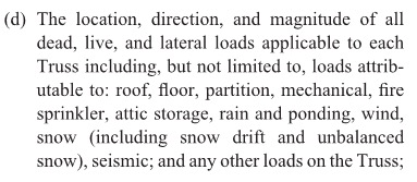
In our second blog in the “How to Pick a Connector Series,” Randy Shackelford discussed the various considerations involved in selecting a joist hanger. So why is this blog post about truss hangers? A hanger is a hanger, right? Before I moved into the Engineering Department at Simpson Strong-Tie, I was the product manager for our Plated Truss product line. I can assure you that there is a bit more that goes into the selection (and design) of a truss hanger than does into selecting a joist hanger!

Of course, all of the considerations that were covered in the joist hanger blog apply to truss hangers as well. This blog post is going to discuss some additional considerations that come into play in selecting a hanger for a truss rather than a joist, and how some hangers have features designed especially for trusses.

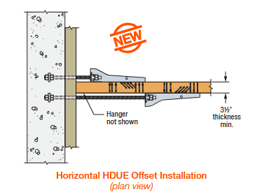
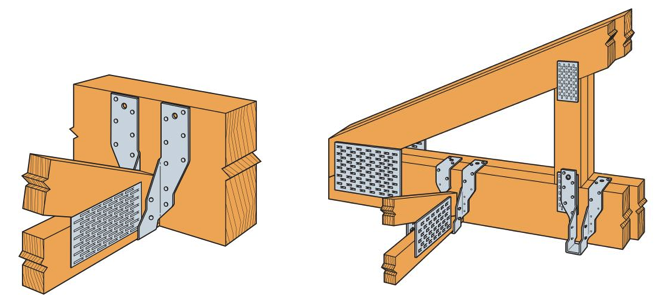
The first (and most obvious) truss-specific consideration is the presence of webs. Because of truss webs, top-flange hangers are not as conducive to truss applications as they are to joist applications. A better alternative for trusses is an adjustable-strap hanger that can be installed as a top-flange hanger or face-mount hanger. Take the THA29, for example, Simpson’s first hanger developed specifically for the truss industry (circa 1984). It can accommodate different girder bottom chord depths, which eliminates the need for multiple SKUs, and the straps can be field-formed over the top of the girder bottom chord to reduce the number of fasteners (just like top-flange hangers). When a web member is in the way of the top-flange installation method, the straps can be attached vertically to the web in a face-mount installation instead.

Typical THA29 Installation

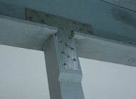
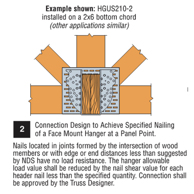
What if the web at that location isn’t vertical? You can still install the strap onto the web, but if any nails land in the joint lines formed by the intersection of the wood members, they cannot be considered effective. Therefore, the hanger allowable load may need to be reduced to account for ineffective header nails. This alternative installation is acceptable for any face-mount hanger located at a panel point as shown in our catalog (see detail below).

hgus2102-installed

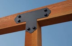
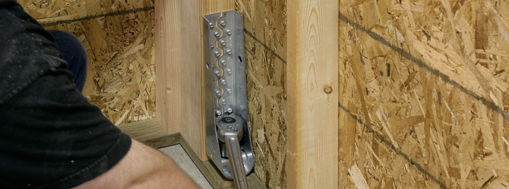
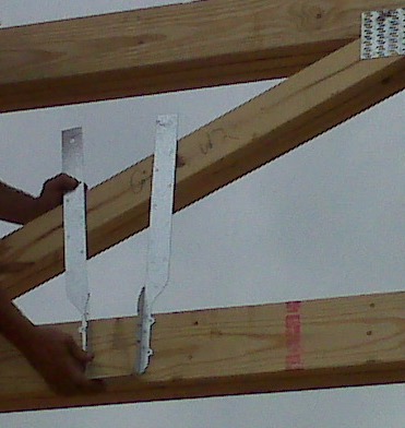
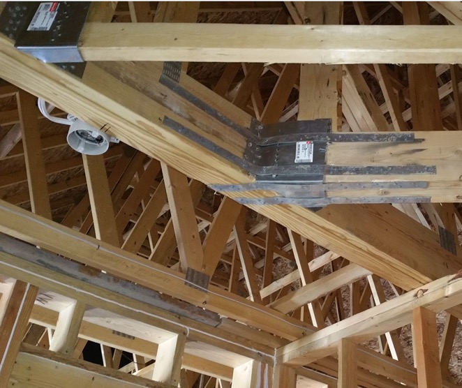
Although very versatile, not all adjustable-strap hangers can be installed on all sizes of bottom chords. Our catalog specifies a C-dimension for these hangers, which corresponds to the height of the side-nailing flanges. If that dimension exceeds the height of the bottom chord, then the straps cannot be field-formed as needed for the top-flange installation. And if the hanger isn’t located at a panel point, nailing the straps to any diagonal web that the straps can reach (see photo below) is not an acceptable option!

The wrong hanger selection for the application

Another unique consideration that goes into the selection of a truss hanger is the heel height of the carried truss. A truss with a short heel height installed into a tall hanger will likely leave air (or “daylight,” as I call it) behind a lot of the nail holes running up the side flanges. When nail holes in a hanger have air behind them instead of wood, this equates to a reduction in hanger capacity. So when the carried truss has a heel height that is much less than the depth of the carrying member (and the hanger), it is important to use the appropriate hanger capacity for that condition and not overestimate the hanger’s capacity. Refer to our technical bulletin T-REDHEEL for allowable loads for reduced heel height conditions.

Example of a short heel installed in a tall hanger.

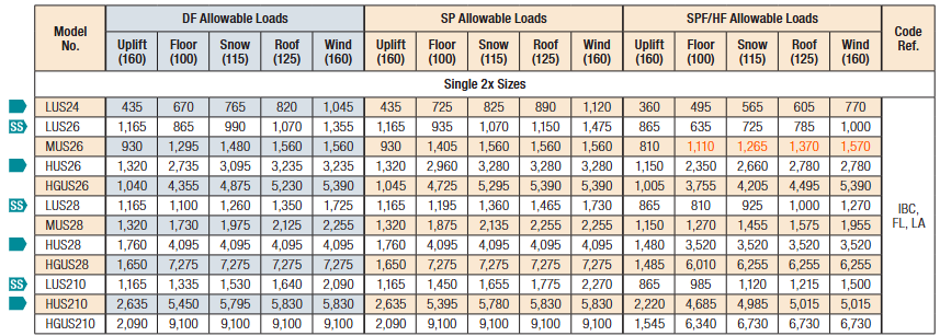
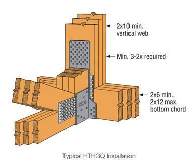
Because trusses are capable of carrying a lot of load –  and producing large reactions –  hangers for truss applications often require larger capacities than joist hangers. Unfortunately, there is only so much capacity that can be achieved from a hanger that fits entirely onto a girder truss bottom chord. Therefore, in order to use our highest load-rated truss hangers, a properly located vertical web is required, and the web must be wide enough for the hanger’s required face fasteners and minimum edge distances. The more capacity that is required, the more fasteners it takes, and the wider the vertical web must be. Our highest-load-rated truss hanger that installs with screws is the HTHGQ. It has a maximum download capacity of 20,735 lb., but it requires a minimum 2×10 vertical web. The THGQ/THGQH series can be installed onto as small as a 2×6 web, but the maximum possible capacity on a 2×6 web is 9,140 lb.

hthgq-installation

In addition to high-capacity hangers, truss applications often require high-capacity skewed hangers. When selecting skewed hangers, it’s important to realize that hangers with custom skew options usually have a reduction that must be applied to the hanger’s 90-degree capacity.  Another important factor that is sometimes overlooked in the selection of skewed hangers is whether the carried member is square-cut or bevel-cut. When the member is square cut – as in the case of trusses – not only does this typically result in a greater reduction in capacity, but some skewed hangers cannot be used at all with square-cut members. For example, the fastener holes on the side flange may not be located far enough away from the header to accommodate square-cut members. See the photo below for an example of what can happen if a skewed hanger that is intended for a bevel-cut member is used for a truss.

Incorrect hanger selection – this skewed hanger requires the carried member to be bevel-cut whereas the truss is square-cut.
Not all skewed hangers can be used with square-cut members (trusses).

As discussed in the previous hanger blog, face-mount hangers offer the advantage of being installed after the joist (or truss) is installed. What if the truss is installed prior to the hanger and a gap exists between the truss and the carrying member? In that case, the best option may be to select a truss hanger that was designed with this type of installation tolerance in mind, the HTU hanger. Other face-mount truss hangers that use double-shear nailing are great when gaps are limited to ⅛” or less, but their capacities take a pretty large hit when the gap exceeds ⅛” (see our previous blog Minding the Gap in Hangers for more information). The HTU was designed to give an allowable load for up to a ½” gap between the end of the truss and the carrying member. In addition, it has built-in nailing options to accommodate short heel heights even in the taller models – definitely a truss hanger!

HTU Hanger
HTU Hanger

Finally, there is one more thing to consider when selecting a face-mount hanger for a truss application, which relates to how tall the carrying member is compared to the hanger. Assuming the bottom of the hanger will be installed flush with the bottom of the girder bottom chord, a hanger that is much shorter than the bottom chord will induce tension perpendicular to the grain in the chord. Due to wood’s inherent weakness in perpendicular-to-grain tension, a hanger that is too short may limit the amount of load that can be transferred– to something less than the hanger’s published allowable load. Therefore, it isn’t enough to check whether the hanger fits on the bottom chord; the hanger must also cover enough depth of the chord to effectively transfer the load (or else the allowable hanger load may need to be reduced to the member’s allowable cross-grain tension limit).

Cross-grain tension is not a truss-specific issue, but because it is an explicit design provision in the truss design standard (TPI 1), it is a necessary consideration to mention in a discussion about truss hanger selection. In fact, proper detailing for cross-grain tension in different wood applications could be a future topic in and of itself.

Add to all this the specialty truss hangers that can carry two, three, four, and even five trusses framing into one location, and it is no wonder that there is an entire section in our catalog that is dedicated to truss hangers. Are there any other truss hanger needs that you would like to discuss? Please let us know in the comments below!


Great ShakeOut Earthquake Drill 2016

The Great ShakeOut Earthquake Drill is an annual opportunity for people in homes, schools and organizations to practice what to do during earthquakes and improve their preparedness. In a post I wrote last October about the Great ShakeOut, I reminisced about the first earthquake I had to stop, drop and cover for – the Livermore earthquake in January, 1980. This year got me thinking about how our evacuation drills work.

At Simpson Strong-Tie, we use the annual Great ShakeOut drill to practice our building evacuation procedures. Evacuation drills are simple in concept – alarms go off and you exit the building. We have volunteer safety wardens in different departments who confirm that everyone actually leaves their offices. There are always a few people who want to stay inside and finish up a blog post. Once the building is empty and we have all met up in the designated meeting area, we do a roll call and wait for the all-clear to get back to work.

Several years ago the alarms went off. While waiting for the drill to end, we were concerned to see fire fighters arrive and rush into the building. Realizing this was not a drill, there were some tense moments of waiting. The fire chief and our president eventually walked out of the building and our president was yelling for one of our engineers. Turns out the engineer (who shall remain nameless) was cooking a chicken for lunch. Yes, a whole chicken. The chicken didn’t make it – I’m not sure what the guilty engineer had for lunch afterwards. At least we received extra evacuation practice that year. We aren’t allowed to cook whole chickens in the kitchen anymore.

Simpson Strong-Tie is helping increase awareness about earthquake safety and encouraging our customers to participate in the Great ShakeOut, which takes place next Thursday on October 20. It’s the largest earthquake drill in the world. More than 43 million people around the world have already registered on the site.

On October 20, from noon to 2:00 p.m. (PST), earthquake preparedness experts from the Washington Emergency Management Division and FEMA will join scientists with the Washington Department of Natural Resources and the Pacific Northwest Seismic Network for a Reddit Ask Me Anything – an online Q&A. Our very own Emory Montague will be answering questions. The public is invited to ask questions here. (Just remember that this thread opens the day before the event and not sooner.)

Emory Montague from Simpson Strong-Tie
Emory, ready to answer some seismic-related questions.

We’re also providing resources on how to retrofit homes and buildings, and have information for engineers here and for homeowners here.

Earthquake risk is not just a California issue. According to the USGS, structures in 42 of 50 states are at risk for seismic damage. As many of you know, we have done a considerable amount of earthquake research, and are committed to helping our customers build safer, stronger homes and buildings. We continue to conduct extensive testing at our state-of-the-art Tye Gilb lab in Stockton, California. We have also worked with the City of San Francisco to offer education and retrofit solutions to address their mandatory soft-story building retrofit ordinance and have created a section on our website to give building owners and engineers information to help them meet the requirements of the ordinance.

Last year, Tim Kaucher, our Southwestern regional Engineering Manager, wrote about the City of Los Angeles’s Seismic Safety Plan in this post. Since that time, the City of Los Angeles has put that plan into action by adopting mandatory retrofit ordinances for both soft-story buildings and non-ductile concrete buildings. Fortunately, California has not had a damaging earthquake for some time now. As a structural engineer, I find it encouraging to see government policy makers resist complacency and enact laws to promote public safety.

Participating in the Great ShakeOut Earthquake Drill is a small thing we can all do to make ourselves more prepared for an earthquake. If your office hasn’t signed up for the Great ShakeOut Earthquake Drill, we encourage you to visit shakeout.org and do so now.