


Floors and roofs on mass timber buildings are constructed from large panels of engineered wood, such as cross-laminated timber (CLT) or mass plywood. Designers join these prefabricated panels together on site to create a structural horizontal diaphragm to transfer wind and seismic loads to the vertical elements of the lateral force resisting system. Shear forces between panels must be transferred through these panel-to-panel connections. Conventional wood structural panel sheathed diaphragms have shear capacities and fastener spacing tabulated in Special Design Provisions for Wind and Seismic (AWC SDPWS). Mass timber diaphragms, on the other hand, require some more design work by the designer.
Tag: testing

Take a Tour of Our McKinney R&D Lab
Did you know that Simpson Strong-Tie has a research and development lab in our McKinney, Texas, branch? In the following article, Francisco, the McKinney branch lab manager, talks about the history of this lab and what we do there.

My Experience as an Engineering Intern from Gallatin, Tennessee
This summer we welcomed engineering student Sam Lewis to intern at our Gallatin, Tennessee branch. He discusses his hands-on opportunity to test our fasteners, learn more about our company culture and people.

Touring Tye Gilb Lab: An Architectural Engineering Student’s Perspective
Addie Albro is an architectural engineering student at California Polytechnic State University in San Luis Obispo. She’s working on completing her senior project while learning how to design with steel, timber, masonry, and concrete. We recently had the opportunity to host Addie and other Cal Poly undergrads at our Tyrell Gilb Lab in Stockton, California. She shared her experience visiting the lab and what inspired her to enter the engineering field.

How Should I Determine a Tension Test Load? Guidelines on Proof Loading Adhesive Anchors
Have you ever been involved on a project where a post-installed anchor failed when loaded? What was the circumstance? Was the anchor installed with incorrect torque or was the hole improperly cleaned, resulting in lower capacities than published? Unfortunately, in the world of concrete anchors, installations are sometimes incorrect as a result of not following instructions. Alternatively, perhaps you’re working on a project where special inspection wasn’t performed as required by the building code. What should be done in these cases?

Outdoor Accents: Timeless Design Meets Tested Strength
Like everyone else in the world, I’ve been spending more time at home these past few months. More than I ever have before. During this time, I’ve found myself thinking about all the home improvement projects that would make our outdoor space more enjoyable. It’s something that in the extreme busyness of our “normal” life, I didn’t have a lot of time for. But being home 24/7 with two energetic and loud little boys has meant a lot of outside time. As a California native, I am grateful to be able to enjoy beautiful outdoor weather most of the year. I love being outside with my family, hanging out in the backyard, escaping all the tempting electronic devices that are constantly pulling us in. And now, more than ever, while sheltering –in place during the COVID-19 pandemic, I’m so thankful for a backyard that we can enjoy. So, topping my backyard home improvement project list: adding a shade structure, like a pergola or pavilion.

Revisiting Spanning the Gap

Three years ago, we created this blog post based on a technical support question we often receive about allowable fastener loads for ledgers to wood framing over gypsum board. Given that this is still a frequent question and a relevant topic, we decided to revisit the post and update it.
Drywall. Wall board. Sheetrock. Sackett Board? A product called Sackett Board was invented in the 1890s, which was made by plastering within wool felt paper. United States Gypsum Corporation refined Sackett Board for several years until 1916, when they developed a new method of producing boards with a single layer of plaster and paper. This innovation was eventually branded SHEETROCK®. More details about the history of USG can be found here.
No matter what you call it, gypsum board is found in almost every type of construction. Architects use it for sound and fire ratings, while structural engineers need to account for its weight in our load calculations. A common technical support question we receive is for allowable fastener loads for ledgers to wood framing over gypsum board.
One method to evaluate a fastener spanning across gypsum board is to treat the gypsum material as an air gap. Technical Report 12, General Dowel Equations for Calculating Lateral Connection Values, is published by the American Wood Council.

TR12 has yield limit equations that allow a designer to account for a gap between the main member and side member of a connection. With a gap of zero (g=0), the TR12 equations provide the same results as the NDS yield limit equations.
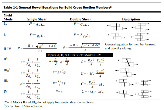
The equations are fairly complex, but it should be intuitive that the calculated fastener capacity decreases with increasing gap. Engineers are often surprised to see a 40, 50, even 60% drop in fastener capacity with one layer of 5/8” gypsum board. So what else can you do?
Testing, of course! In So, What’s Behind a Screw’s Allowable Load? I discussed the methods used to load rate a proprietary fastener such as the Simpson Strong-Tie® Strong-Drive® SDS or SDW screws. To recap, ICC-ES Acceptance Criteria for Alternate Dowel Type Fasteners, AC233, allows you to calculate and do verification tests, or load rate based on testing alone. We develop our allowable loads primarily by testing, as the performance enhancing features and material optimizations in our fasteners are not addressed by NDS equations.
So to determine the performance of a fastener installed through gypsum board, we tested the fastener through gypsum board. This is easier to do if you happen to have a test lab with a lot of wood and fasteners in it. We did have to run down to the local hardware store to pick up gypsum board for the testing.
A full set of allowable loads for Strong-Drive SDWH and SDWS are available on strongtie.com. The information is given as single fastener shear values for engineered design, and also screw spacing tables for common ledger configurations. As much fun as writing spreadsheets to do the Technical Report 12 calculations is, having tabulated values based on testing is much easier.
Fastening Systems
In the fastener marketplace, Simpson Strong-Tie stands apart from the rest. Quality and reliability is our top priority.

5 Steps to a Successful Soft-Story Retrofit
Last year, I gave a presentation at the annual National Council of Structural Engineers Associations (NCSEA) Summit in Orlando, Florida, titled “Becoming a Trusted Advisor: Communication and Selling Skills for Structural Engineers.” As this was a summit for the leaders of the structural engineers associations from across the country, I wasn’t sure how many people would find it valuable to spend their time learning about a very nontechnical topic. To my surprise and delight, the seminar ended up being standing-room only, and I was able to field some great questions from the audience about how they could improve their selling and communication skills. In the many conversations I had with the conference attendees after my presentation, the common theme was that engineers felt they needed more soft-skills training in order to better serve their clients. The problem, however, was finding the time to do so when faced with the daily grind of design work.
When I started my first job as a design engineer at a structural engineering consulting firm straight out of school, I was very focused on improving and expanding my technical expertise. Whenever possible, I would attend building-code seminars, design reviews and new product solution presentations, all in an effort to learn more about structural engineering. What I found as I progressed through my career, however, was that no matter how much I learned or how hardworking I was, it didn’t really matter if I couldn’t successfully convey my knowledge or ideas to the person who really mattered most: the client.

How can an engineer be most effective in explaining a proposed action or solution to a client? You have to be able to effectively sell your idea by understanding the needs of your client as well as any reasons for hesitation. The importance of effective communication and persuasion is probably intuitive to anyone who’s been on the sales side of the business, but not something that occurs naturally to data-driven folks like engineers. As a result of recent legislation in California, however, structural engineers are starting to be inundated with questions from a group of folks who have suddenly found themselves responsible for seismically upgrading their properties: apartment building owners in San Francisco and Los Angeles.
Imagine for a moment that you are a building owner who has received a soft-story retrofit notice under the City of Los Angeles’ Ordinance 183893; you have zero knowledge of structural engineering or what this term “soft-story” even means. Who will be your trusted advisor to help you sort it out? The City of Los Angeles Department of Building and Safety (LADBS) has put together a helpful mandatory ordinance website that explains the programs and also offers an FAQ for building owners that lets them know the first step in the process: hire an engineer or architect licensed in the state of California to evaluate the building.

I’ve had the opportunity to be the first point of contact for a building owner after they received a mandatory notice, because it turns out some relatives own an apartment building with soft-story tuck-under parking. Panicked by the notice, they called me looking to understand why they were being forced to retrofit a building that “never had any problems in the past.” They were worried they would lose rent money due to tenants needing to relocate, worried about how to meet the requirements of the ordinance and, most importantly, worried about how much it was going to cost them. What they really wanted was a simple, straightforward answer to their questions, and I did my best to explain the necessity behind retrofitting these vulnerable buildings and give an estimated time frame and cost that I had learned from attending the first Los Angeles Retrofit Resource Fair in April 2016. With close to 18,000 buildings in the cities of San Francisco and Los Angeles alone that have been classified as “soft-story,” this equates to quite a number of building owners who will have similar questions and be searching for answers.
To help provide an additional resource, Simpson Strong-Tie will be hosting a webinar for building owners in the Los Angeles area who have received a mandatory soft-story retrofit notice. Jeff Ellis and I will be covering “5 Steps to a Successful Retrofit” and helping to set a clear project path for building owners. The five steps that Simpson Strong-Tie will be recommending are:
- Understanding the Seismic Retrofit Mandate
- Partnering with Design Professionals
- Submitting Building Plans with the Right Retrofit Product Solutions
- Communicating with Your Building Tenants
- Completing Your Soft-Story Retrofit
We encourage you to invite any clients or potential clients to attend this informative webinar, which will lay the foundation for great communication between the two of you. As part of the webinar, we will be asking the building owners for their comments, questions and feedback so we can better understand what information they need to make informed decisions, and we will be sure to share these with the structural engineering community in a future post. By working together to support better communication and understanding among all stakeholders in retrofit projects, we will be well on our way to creating stronger and more resilient communities!
For additional information or articles of interest, there are several resources available:
- Register for the “5 Steps to a Successful Retrofit” webinar on April 26
- Register to attend the 2nd Los Angeles Seismic Retrofit Resource Fair on April 17 (and stop by the Simpson Strong-Tie booth!)
- Find a structural engineer through the Structural Engineers Association of Southern California (SEAOSC)
- Resilience by Design: City of Los Angeles Lays Out A Seismic Safety Plan
- City of San Francisco Implements Soft-Story Retrofit Ordinance
- Soft-Story Retrofits Using the New Simpson Strong-Tie Retrofit Design Guide
- Visit the Simpson Strong-TieSoft-Story Retrofit Center
- The Los Angeles Times Soft-Story Map

Testing Fasteners for Deck Ledger Connections
This week’s blog post was written by Aram Khachadourian, R&D Engineer for Fastening Systems. Since joining Simpson Strong-Tie 14 years ago, he has designed and tested holdowns, hangers, truss connectors and anchor bolts. He has drafted numerous acceptance criteria as well as quality standards. His current focus is the development, testing and code approval of structural fasteners. Prior to his work at Simpson Strong-Tie, he spent his time designing steel buildings including strip malls, wineries and airplane hangars. Aram graduated from the University of California at Davis with a Civil Engineering degree, and is a registered professional engineer in California.
As we approach the beginning of spring, homeowners across the country are starting to turn their thoughts to the backyard and making plans to add a new deck for summer enjoyment.
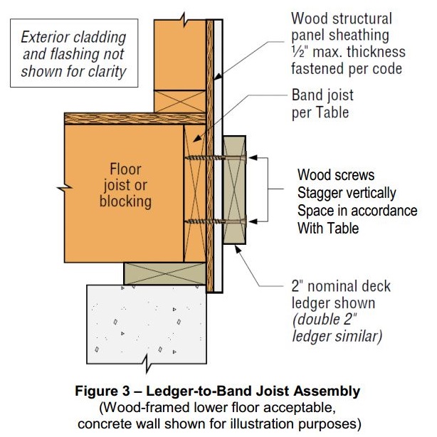
As a contractor, designer, or homeowner, you want to know that this new deck will have the structural integrity to stand firm for many years and remain safe for everybody who will use it. While there are many aspects to building a safe, strong deck, today we are focusing on the attachment of the deck ledger to the structure.
Prior to 2009, numerous catastrophic deck failures attributed to improper deck ledger attachments demonstrated the need for building code guidance. A calculated solution was overly conservative because the sheathing layer, typically present between the deck ledger and the structure’s band joist, was considered to be a gap in the connection. A prescriptive approach to deck ledger attachments was finally introduced in the 2009 International Residential Code (IRC). Table R502.2.2.1 provided fastener spacings for ½”-diameter lag screws and bolts. These values were based on testing conducted by researchers at Virginia Tech and Washington State University.
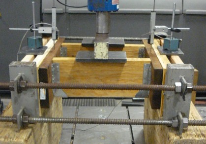
The tests included a variety of band joist types, with pressure-treated Hem-Fir as the deck ledger material. The deck ledger was tested at high moisture content to represent a wet, worst-case field condition. The test assembly had a load bar spanning two joists that were attached to the deck ledger with joist hangers. The ledger was attached through the sheathing to the rim board. Only the rim board was supported by the test frame. The average ultimate load was divided by a factor-of-safety of 3 and then further divided by the load duration coefficient of 1.6 to achieve an allowable load. These values were then applied to a deck live load of 40 psf plus a deck dead load of 10 psf to derive allowable fastener on-center spacings for various joist spans.
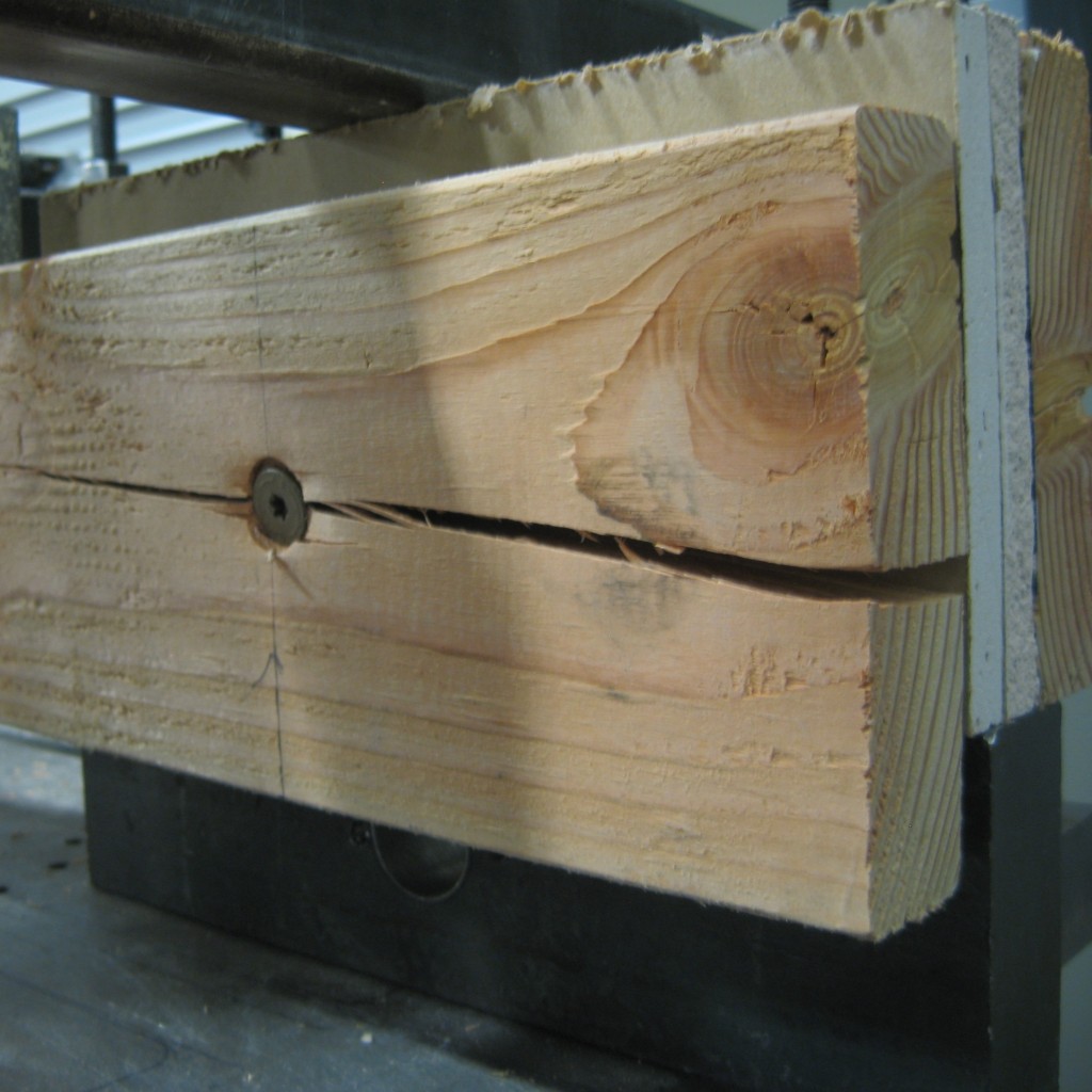
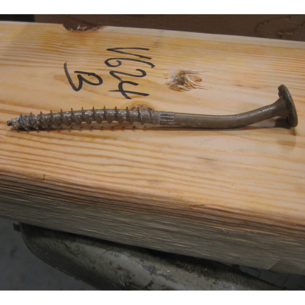
When Simpson Strong-Tie began to rate fasteners for ledger connections, we used a similar method of testing and analysis. However, we incorporated a few changes. One of the changes we implemented was a symmetric test set-up. The original test assembly had a ledger on one end of the joists and a support member as the boundary condition on the other. We put a ledger at each end of the joists so stiffness differences in the supports would not affect the test results. We also chose a larger factor-of-safety of 3.2 (instead of 3.0) to maintain consistency with calculation of fastener allowable loads in other applications. In order to provide our customers with a broader range of construction options, we tested many typical rim board and ledger materials, and we ran tests with single and double ledgers. You can see an example of a typical test set up here:
We have tested many Simpson Strong-Tie® Strong-Drive® fasteners for ledger applications including the SDWS Timber screw (SDWS22DB), SDWH Timber-Hex SS screw (SDWH-SS), SDWH Timber-Hex screw (SDWH19DB), and SDS Heavy-Duty Connector screw (SDS). We also have information regarding ledgers attached to studs and ledgers fastened over gypsum board. You can find all of this information in our latest fastener catalog.
One final construction tip – deck ledgers can fail due to cross-grain tension. This occurs when the joist hangers are attached to the deck ledger near the bottom of the ledger, but the fasteners holding the ledger to the building are near the top of the ledger. To prevent cross-grain tension failure, place the joist hangers so at least half of the ledger fasteners are below the joist hanger line.
Take a look through the various ledger options in our fastener catalog, and if we don’t address your condition, let us know. As always, call us in the Engineering Department if you have questions.
Please share your feedback in the comments area below.
Narrow Face Installations
Engineered wood products have been used in wood-framed construction for many decades. Early forms of engineered wood include plywood as replacement for 1x wood sheathing and glu-laminated beams that could be fabricated in larger sizes with optimized material utilization. I-joists utilizing deep plywood webs and solid sawn lumber flanges solved the challenge of longer floor spans. Oriented strand board (OSB) eventually replaced plywood in the webs, while the innovation of laminated veneer lumber (LVL) became common in the flange material.
In addition to I-joists, structural composite lumber is widely used as a replacement for solid lumber. This could be for a number of reasons such as availability of longer lengths, straighter sections and higher strengths. Structural composite lumber (SCL) may be LVL, parallel strand lumber (PSL), laminated strand lumber (LSL) or oriented strand board (OSB).
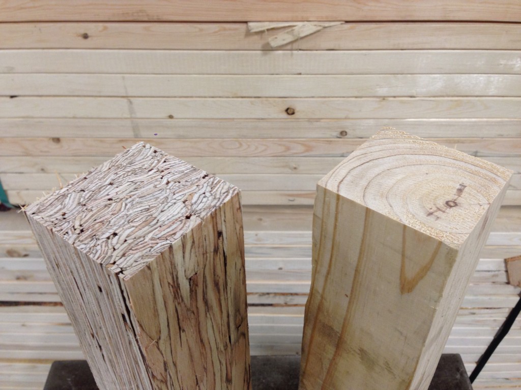
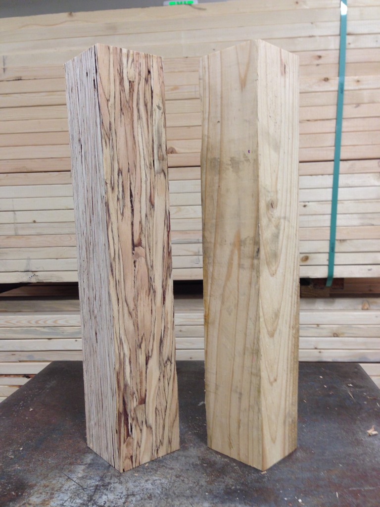
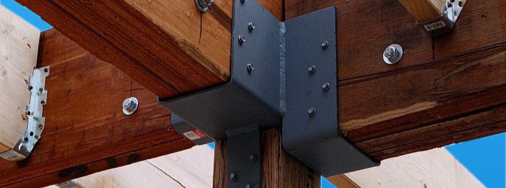
Structural composite lumber has two faces. If the cross-section is rectangular, say 3½x5¼, the narrow face will show the edges of the SCL layers. In a square section, the face that shows the SCL layers is still referred to as the narrow face. Fasteners will have lower performance when they are installed in the narrow face of SCL. While this is not an issue for beams, Simpson Strong-Tie connectors such as post bases, column caps or holdowns may have reduced allowable loads when installed on the narrow face of SCL columns.
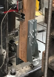


To support the use of Simpson Strong-Tie connectors installed on SCL post material, we have run many tests over the years. The reductions are published in the technical bulletins, T-C-SCLCLM25 (U.S. version) and T-C-SCLCLMCAN25. The reduction factors range from 0.45 to 1.0, and vary based on SCL material type – LSL, PSL, or LVL – and also by connector and fastener type.
It is important to understand the magnitude of the reductions. While narrow face installations may be unavoidable, engineers will need to specify the correct lumber and hardware combination to meet the design loads.
Share additional thoughts by leaving a comment.