

Have you ever been at home during an earthquake and the lights turned off due to a loss of power? Imagine what it would be like to be in a hospital on an operating table during an earthquake or for a ceiling to fall on you while you are lying on your hospital bed.
Category: Academia
Our academia posts are dedicated to helping our customers and the general public acquire a deeper understanding of solutions and how they relate to the industry.
Wood-framed Deck Guard Post Resources and Residential Details
A deck and porch study reported that 33% of deck failure-related injuries over the 5-year study period were attributed to guard or railing failures. While the importance of a deck guard is widely known, there was a significant omission from my May 2014 post on Wood-framed Deck Design Resources for Engineers regarding the design of deck guards.
A good starting point for information about wood-framed guard posts is a two-part article published in the October 2014 and January 2015 issues of Civil + Structural Engineer magazine. “Building Strong Guards, Part 1” provides an overview of typical wood-framed decks, the related code requirements and several examples that aim to demonstrate code-compliance through an analysis approach. The article discusses the difficulties in making an adequate connection at the bottom of a guard post, which involve countering the moment generated by the live load being applied at the top of the post. Other connections in a typical guard are not as difficult to design through analysis. This is due to common component geometries resulting in the rails and balusters/in-fill being simple-supported rather than cantilevered. “Building Strong Guards, Part 2” provides information on the testing approach to demonstrate code-compliance. Information about code requirements and testing criteria are included in the article as well.
Research and commentary from Virginia Tech on the performance of several tested guard post details for residential applications (36” guard height above decking) is featured in an article titled “Tested Guardrail Post Connections for Residential Decks” in the July 2007 issue of Structure magazine. Research showed that the common construction practice of attaching a 4×4 guard post to a 2x band joist with either ½” diameter lag screws or bolts, fell significantly below the 500 pound horizontal load target due to inadequate load transfer from the band joist into the surrounding deck floor framing. Ultimately, the research found that anchoring the post with a holdown installed horizontally provided enough leverage to meet the target load. The article also discussed the importance of testing to 500 pounds (which provides a safety factor of 2.5 over the 200-pound code live load), and the testing with a horizontal outward load to represent the worst-case safety scenario of a person falling away from the deck surface.
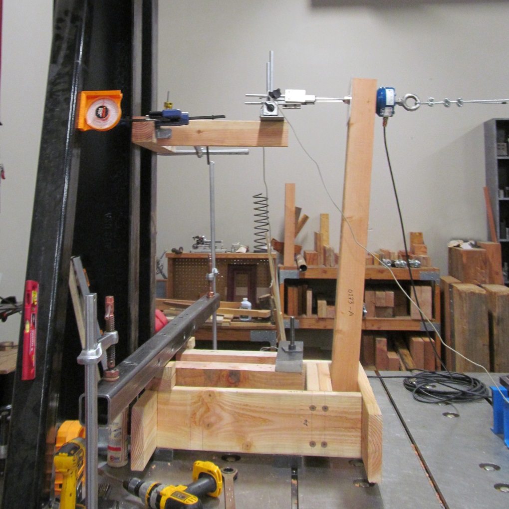
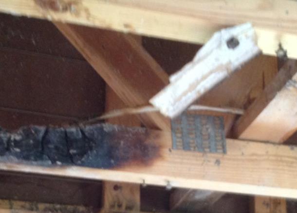
Simpson Strong-Tie has tested several connection options for a guard post at the typical 36” height, subjected to a horizontal outward load. Holdown solutions are included in our T-GRDRLPST10 technical bulletin. In response to recent industry interest, guard post details utilizing blocking and Strong-Drive® SDWS TIMBER screws have been developed (see picture below for a test view) and recently released in the engineering letter L-F-SDWSGRD15. The number of screws and the blocking shown are a reflection of the issue previously identified by the Virginia Tech researchers – an adequate load path must be provided to have sufficient support.
Have you found any other resources that have been helpful in your guard post designs? Let us know by posting a comment.
24th Short Course on CFS Structures:
October 27-29 in St. Louis
Simpson Strong-Tie is sponsoring the 24th Short Course on Cold-Formed Steel Structures hosted by the Wei-Wen Yu Center for Cold-Formed Steel Structures (CCFSS). The course will be held on October 27-29, 2015 at the Drury Plaza Hotel at the Arch in St. Louis, MO.
This three-day course is for engineers who have limited or no experience designing with cold-formed steel (CFS), as well as those with experience who would like to expand their knowledge of cold-formed steel structural design. Lectures will be given by industry-recognized experts Roger LaBoube, Ph.D., P.E., and Sutton Stephens, Ph.D., P.E., S.E. The course is based on the 2012 AISI North American Specification for the Design of Cold-Formed Steel Structural Members and the 2012 North American Standards for Cold-Formed Steel Framing. Dr. Wei-Wen Yu’s book Cold-Formed Steel Design (4th Edition) will be a reference text.
The course will address such topics as design of wall studs, floor joists, purlins, girts, decks and panels. It is eligible for 2.4 Continuing Education Units (CEUs). Advance registration is requested by October 10, 2015. For more information and to register, click here.
24th Short Course on CFS Structures: October 27-29 in St. Louis
Simpson Strong-Tie is sponsoring the 24th Short Course on Cold-Formed Steel Structures hosted by the Wei-Wen Yu Center for Cold-Formed Steel Structures (CCFSS). The course will be held on October 27-29, 2015 at the Drury Plaza Hotel at the Arch in St. Louis, MO.
This three-day course is for engineers who have limited or no experience designing with cold-formed steel (CFS), as well as those with experience who would like to expand their knowledge of cold-formed steel structural design. Lectures will be given by industry-recognized experts Roger LaBoube, Ph.D., P.E., and Sutton Stephens, Ph.D., P.E., S.E. The course is based on the 2012 AISI North American Specification for the Design of Cold-Formed Steel Structural Members and the 2012 North American Standards for Cold-Formed Steel Framing. Dr. Wei-Wen Yu’s book Cold-Formed Steel Design (4th Edition) will be a reference text.
The course will address such topics as design of wall studs, floor joists, purlins, girts, decks and panels. It is eligible for 2.4 Continuing Education Units (CEUs). Advance registration is requested by October 10, 2015. For more information and to register, click here.
BRACE FOR IMPACT! Bracing Design for Cold-Formed Steel Studs
While consideration of bracing is important for any structural element, this is especially true for thin, singly symmetric cold-formed steel (CFS) framing members such as wall studs. Without proper consideration of bracing, excessive buckling or even failure could occur. Bracing is required to resist buckling due to axial or out-of-plane lateral loads or a combination of the two.
There are two methods for bracing CFS studs as prescribed by the American Iron and Steel Institute (AISI) Committee on Framing Standards (COFS) S211 “North American Standard for Cold-Formed Steel Framing – Wall Stud Design” Section B1. One is sheathing braced design and the other is steel braced design.
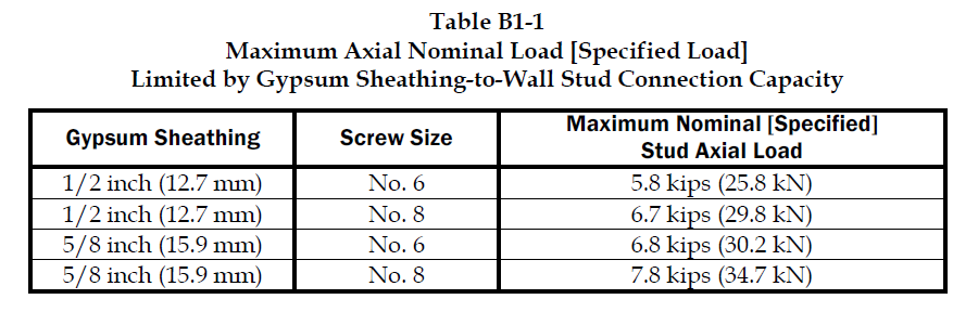
Sheathing braced design has limitations, but it is a cost effective method of bracing studs since sheathing is typically attached to wall studs. This design method is based on an assumption that the sheathing connections to the stud are the bracing points and so it’s limited by the strength of the sheathing fastener to stud connection. Due to this limitation, the Designer has to use a steel braced design for most practical situations. AISI S211 prescribes a maximum nominal stud axial load for gypsum board sheathing with fasteners spaced no more than 12 inches on center. AISI S211 Section B1 and the Commentary discuss the design method and assumptions and demonstrate how to determine the sheathing bracing strength.
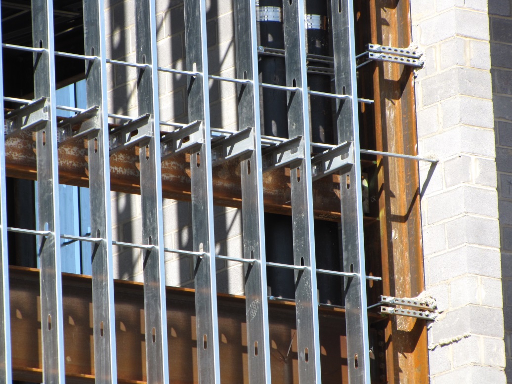
Sheathing braced design requires that identical sheathing is used on each side of the wall stud, except the new AISI S240 standard Section B1.2.2.3 clarifies that for curtain wall studs it is permissible to have sheathing on one side and discrete bracing for the other flange not spaced further than 8 feet on center. The wall stud is connected to the top and bottom tracks or supporting members to provide lateral and torsional support and the construction drawings should note that the sheathing is a structural element. When the sheathing on either side is not identical, the Designer must assume the weaker of the two sheathings is attached to each side. In addition, the Designer is required to design the wall studs without the sheathing for the load combination 1.2D + (0.5L or 0.2S) + 0.2W as a consideration for construction loads of removed or ineffective sheathing. The Designer should neglect the rotational restraint of the sheathing when determining the wall stud flexural strength and is limited by the AISI S100 Section C5.1 interaction equations for designing a wall stud under combined axial and flexural loading.
Steel braced design may use the design methodology shown in AISI S211 or in AISI Committee on Specifications (COS) S100 “North American Specification for the Design of Cold-Formed Steel Structural Members.”
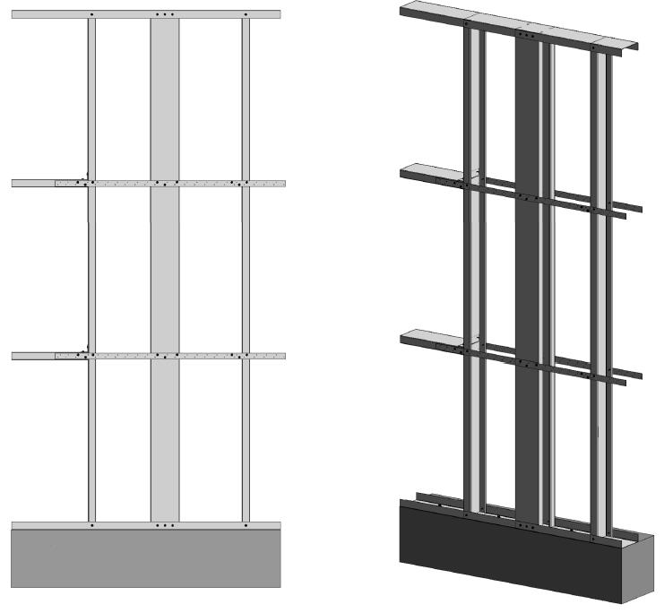
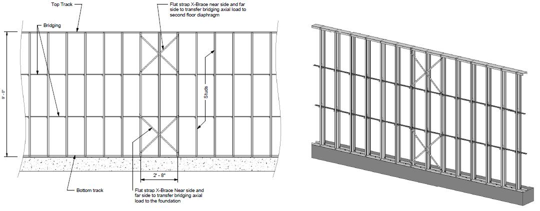
Steel braced design is typically either non-proprietary or proprietary “clip and bridging” bracing, or “flat strap and blocking” bracing periodically spaced along the height of the wall stud.

Proprietary wall bracing and wall stud design solutions can expedite design with load and stiffness tables and software as well as offer efficient, tested and code-listed solutions such as Simpson Strong-Tie wall stud bridging connectors.

Steel braced design is a more practical bracing method for several reasons. First, during construction, wall studs go unsheathed for many months, but are subjected to significant construction loads.This is especially true for load-bearing, mid-rise structures. Second, some sheathing products, including gypsum wallboard, can be easily damaged and rendered ineffective if subjected to water or moisture. Third, much higher bracing loads can be achieved using mechanical bracing. IBC Section 2211.4 permits Designers to design steel bracing for axially loaded studs using AISI S100 or S211. However, S100-07 requires the brace to be designed to resist not only 1% of the stud nominal axial compressive strength (S100-12 changes this to 1% of the required compressive axial strength), but also requires a certain brace stiffness. S211 requires the Designer to design the bracing for 2% of the stud design compression force, and it does not have a stiffness requirement. . AISI S100 is silent regarding combined loading, but S211 provides guidance. S211 requires that, for combined loading, the Designer designs for the combined brace force determined using S100 Section D3.2.1 for the flexural load in the stud and either S100 or S211 for the axial load. In addition, the bracing force for stud bracing is accumulative as stated by S211 Commentary section B3. As a result, the periodic anchorage of the bracing to the structure such as strongbacks or diagonal strap bracing is required.
Some benefits and challenges of steel clip and bridging bracing include:
- Proprietary solutions, such as the Simpson Strong-Tie SUBH bridging connector, can significantly reduce installed cost since many situations require only one screw at each connection.
- Unlike strap bracing, u-channel bracing can be installed from one side of the wall.
- U-channel bracing does not create build-up that can make drywall finishing more difficult.
- Extra coordination may be required to ensure that u-channel bridging does not interfere with plumbing and electrical services that run vertically in the stud bay.
- Bracing for axial loaded studs requires periodic anchorage to the structure, such as using strongbacks or diagonal strap bracing.
- Bracing of laterally loaded studs does not require periodic anchorage since the system is in equilibrium as torsion in the stud is resisted by bridging (e.g., U-channel) bending.
Some benefits and challenges of steel flat strap and blocking bracing include:
- May be installed at other locations than stud punchout.
- Required to be installed on both sides of wall.
- Bumps out sheathing.
- Bracing for axial loaded studs requires periodic anchorage to structure, such as using strongbacks or diagonal strap bracing (same load direction in stud flanges).
- Bracing for laterally loaded studs requires design of periodic blocking or periodic anchorage to the structure (opposite load direction in stud flanges).
There are several good examples Designers may reference when designing CFS wall stud bracing. They include AISI D110 Cold-Formed Steel Framing Design Guide that may be purchased from www.cfsei.org, SEAOC Structural/Seismic Design Manual Volume 2 Example 3 that may be purchased from www.seaoc.org, and the Simpson Strong-Tie wall stud steel bracing design example on page 60 of the C-CFS-15 CFS catalog.
Cold-formed steel framing is a versatile construction material, but Designers need to carefully consider the bracing requirements of the AISI specification and wall stud design standard. What cold-formed steel wall bracing challenges have you encountered and what were your solutions?
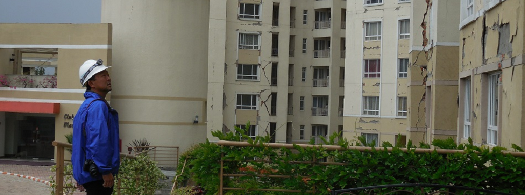
Report Back from Nepal – Assessing Seismic Damage from April/May Earthquakes
As soon as news spread that 7.8-magnitude and 7.3-magnitude earthquakes struck Nepal in April and May of this year, earthquake structural engineering experts from our firm, Miyamoto International, hopped on planes from three countries to offer assistance. We do this in hopes that our expertise and technical advice might help stricken communities recover; help them to build better and ultimately help save lives.Continue Reading

Kids + Structural Engineering = The Tech Challenge!
This week’s post comes from Marlou Rodriguez who is an R&D Engineer at our home office. Prior to joining Simpson Strong-Tie, Marlou worked as a consulting engineer. His experience includes commercial, multi-family residential, curtain wall systems and the design of seismic bracing for non-structural components. Marlou is a licensed professional Civil and Structural Engineer in California, and too many other states to list. He received his bachelor’s degree in Architectural Engineering from Cal Poly San Luis Obispo. Here is Marlou’s post.Continue Reading
Design Examples for Steel Deck Diaphragm Calculator Web App
This week’s blog post was written by Neelima Tapata, R&D Engineer for Fastening Systems. She works in the development, testing and code approval of fasteners. She joined Simpson Strong-Tie in 2011, bringing 10 years of design experience in multi- and single-family residential structures in cold-formed steel and wood, curtain wall framing design, steel structures and concrete design. Neelima earned her bachelor’s degree in Civil Engineering from J.N.T.U in India and M.S. in Civil Engineering with a focus on Structural Engineering from Lamar University. She is a registered Professional Engineer in the State of California.
Like most engineers, you are probably often working against tight deadlines, on multiple projects and within short delivery times. If you have ever wished for a design tool that would make your work easier, we have an app for that. It’s a simple, quick and easy-to-use tool called the “Steel Deck Diaphragm Calculator” for designing steel deck diaphragms. This tool is so user friendly you can start using it in minutes without spending hours in training. This app can be found on our website, and you don’t need to install anything.
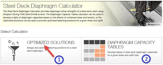
The Steel Deck Diaphragm Calculator has two parts to it: “Optimized Solutions” and “Diaphragm Capacity Tables.” Optimized Solutions is a Designer’s tool and it offers optimized design solutions based on cost and labor for a given shear and uplift. The app provides multiple solutions starting with the lowest cost option using different Simpson Strong-Tie® structural and side-lap fasteners. Calculations can be generated for any of the solutions and a submittal package can be created with the code reports, Factory Mutual Approval reports, fastener information, corrosion information, available fliers, and SDI DDM03 Appendix VII and Appendix IX that includes Simpson Strong-Tie fasteners. Currently, this tool can be used for designing with only Simpson Strong-Tie fasteners. We will be including weld options in this calculator very soon. Stay tuned!
The Diaphragm Capacity Tables calculator can be used to develop a table of diaphragm capacities based on the effects of combined shear and tension.
When “Optimized Solutions” is selected, the following input is requested:
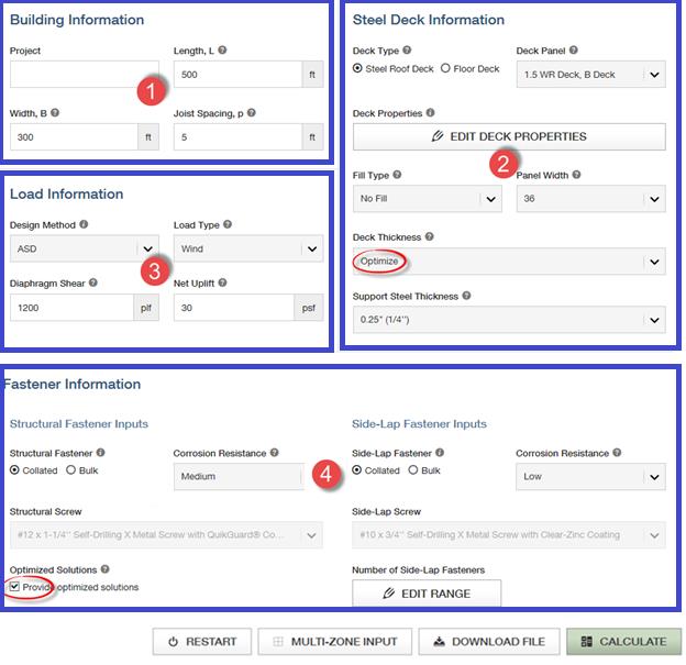
Step 1: Building Information ̶ Enter general information about the project, like the project name, the length and width of the building to be designed along with spacing between the support members such as joist spacing, is entered.
Step 2: Steel Deck Information ̶ Select the type of the steel deck along with the fill type. You can select the panel width from the options or select “Any panel width” option for the program to design the panel width. Choose the deck thickness or select the “Optimize” option for the program to design the optimum deck thickness. You also have an option of editing the steel deck properties to accommodate proprietary decks that are within the limitations of SDI DDM03 Section 1.2. Select the joist steel (support) thickness that the deck material will be attached to. For some fasteners, the shear strength of the fastener is dependent on this support thickness.
Step 3: Load Information ̶ Enter the shear and uplift demand and select the load type as either “wind” or “seismic” and the design method as “ASD” or “LRFD.”
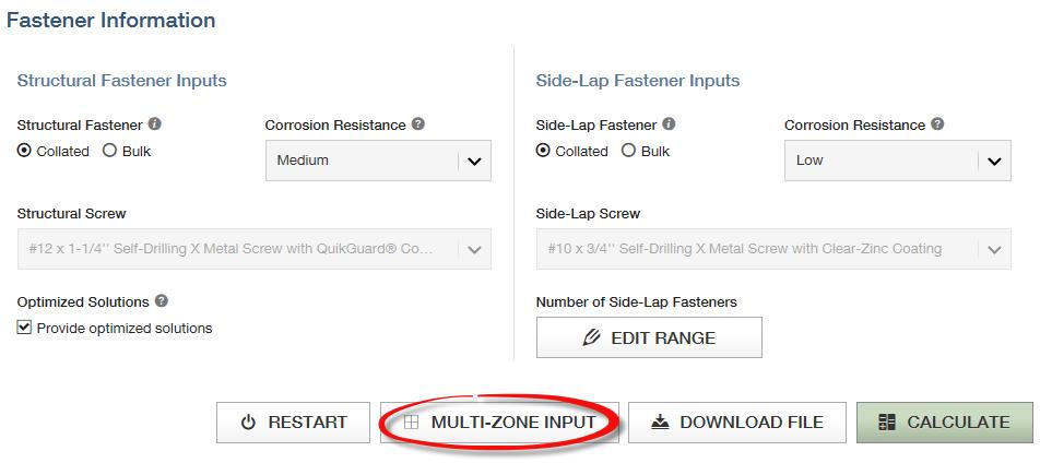
Step 4: Fastener Information ̶ This is the last step of input before designing. In the fastener information section, you have the option to choose a structural and side-lap fastener or let the program design the most cost-effective structural and side-lap options. This can be done by checking the “Provide optimized solutions” option. The default options in the program are usually the best choice. However, you can change or modify as needed for your project. You can also set the side-lap fastener range or leave it to the default of 0 to 12 fasteners.
Now let’s work on an example:
Design a roof deck for a length of L = 500 ft. and a width b = 300 ft. The roof deck is a WR (wide rib) type panel, with a panel width of 36″. The roof deck is supported by joists that are ¼” thick and spaced at 5 ft. on center. Design the diaphragm for wind loading using Allowable Stress Design method. The diaphragm should be designed for a diaphragm shear of 1200 plf. and a net uplift of 30 psf. The steel deck is ASTM A653 SS Grade 33 deck with Fu = 45 ksi.
This information is entered in the web app, as seen below.
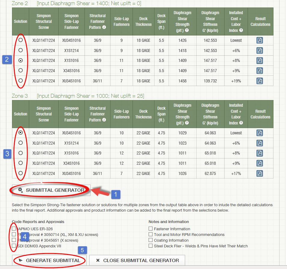
After inputting all the information, click on the Calculate button. You will see the five best solutions sorted by lowest cost and least amount of labor. Then click on the Submittal Generator button. Upon pressing this button, a new column called “Solution” is added with an option button for each solution. You can select any of the solutions. Below the Submittal Generator button, you can select various Code Reports and Approvals and Notes and Information selections that you want included in the submittal. After selecting these items, click on the Generate Submittal button. Now a pdf package will be generated with all of your selections.
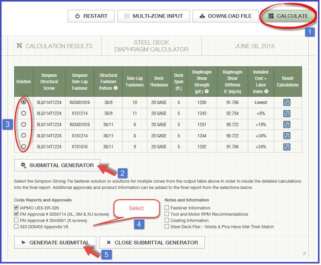
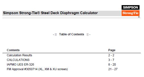
Below is the screen shot of the first page containing Table of Contents from the PDF copy generated. The PDF copy contains the solutions generated by the program, then the detailed calculations for the solution that is selected. In this case, as you can see in the screen shot above, detailed calculations for solution #1 are included with XLQ114T1224 structural screws; XU34S1016 side-lap screws; 36/9 structural pattern and with (10) side-lap fasteners; diaphragm shear strength of 1205 plf. and diaphragm shear stiffness of 91.786 kip/in. The detailed calculations are followed by IAPMO UES ER-326 code report and FM Approval report #3050714.
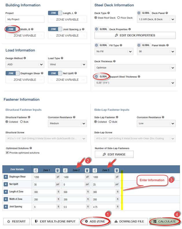
Below is another example of a roof deck to be designed for multiple zones.
Design a roof diaphragm that will be zoned into three different areas. Zoning is a good way to optimize the economy of the roof diaphragm. Below are the required diaphragm shears and uplift in the three zones.
Zone 1: Diaphragm shear = 1200 plf.; Net uplift = 30 psf.; Length and width of zone 1 = 300 ft. x 200 ft.
Joist spacing = 5 ft.
Zone 2: Diaphragm shear = 1400 plf.; Net uplift = 0 psf.; Length and width of zone 2 = 500 ft. x 200 ft.
Joist spacing = 5.5 ft.
Zone 3: Diaphragm shear = 1000 plf.; Net uplift = 25 psf.; Length and width of zone 3 = 300 ft. x 200 ft.
Joist spacing = 4.75 ft.
Refer to the example above for all other information not given.
To design for multiple zones first select the Multi-Zone Input button, which is below the Fastener Information section as shown below:
When you click on the Multi-Zone Input button, you can see a toggle button appearing above a few selections as shown below. The default for the toggle button is  , which means that this selection is same for all the zones. You can click on the toggle button to change to
  . Then the selection below changes to a label and reads Zone Variable. After all the selections that need to be zone variables are selected, click the Add Zone button. Keep adding zones as needed. A maximum of five zones can be added. After creating the zones, add the information for each zone and click the Calculate button.
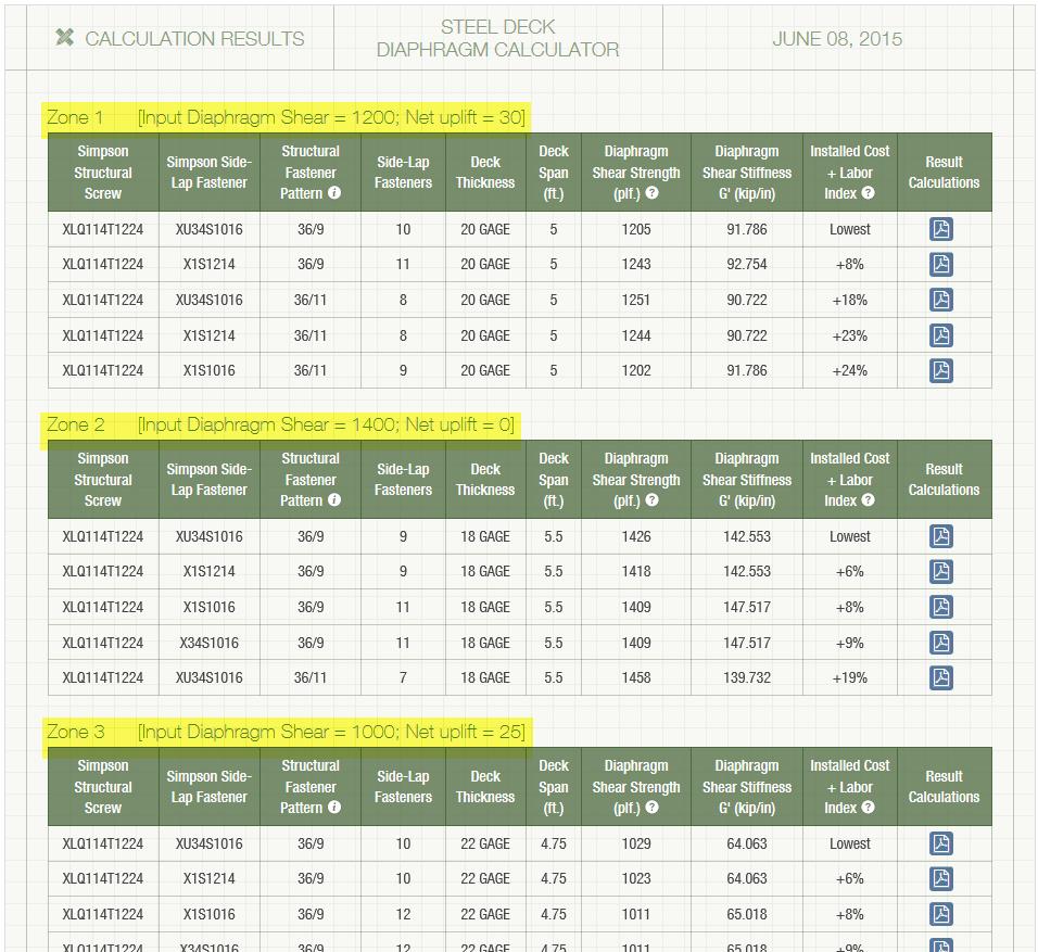
When the Calculate button is clicked, the results for each zone are listed. The five best solutions are listed for each of the zones as shown below.
Similar to previous example, select the Generate Submittal button to select the solutions to be included in the submittal generator. Select one solution for each zone and then check the items like the code reports or notes to be included in the submittal. Click Generate Submittal to create the submittal package.
See the screen shot below for the steps.
Now that you know how easy it is to design using our web app, use this app for your future projects. We welcome your feedback on features you find useful as well as your input on how we could make this program more useful to suit your needs. Let us know in the comments below.
Truss Repair Information: The Never-Ending Search
Truss repair is one of the most frequently asked about truss topics. Not surprisingly, when we asked for suggested truss topics in a truss blog earlier this year, truss repair information made the list. Because the summer months bring about a peak in new construction – and plenty of truss repairs to go along with it – the beginning of June is the perfect time to visit this topic.
From trusses that get dropped or cut/drilled/notched at the jobsite, to homeowners who want to modify their existing trusses to add a skylight or create attic space to fire-damaged trusses, a multitude of scenarios fall under the broad topic of truss repair. Today’s post focuses on various references and resources that can provide some assistance. But first it helps to break down the broad “truss repair” topic into more manageable-sized categories.
New Construction vs. Recent Construction vs. Old Construction
By far, the easiest type of truss repair is new construction, when the trusses either haven’t been installed yet or are still in the process of being installed. Whether the repair is relatively simple (e.g. a broken web) or a little more complicated (e.g. the trusses need to be stubbed), the beauty of new truss construction is that the truss manufacturer – and truss Designer – can be contacted and help with the repair. The truss Designer can easily open up the truss designs in the truss design software, quickly evaluate the trusses for the appropriate field conditions and issue a repair.
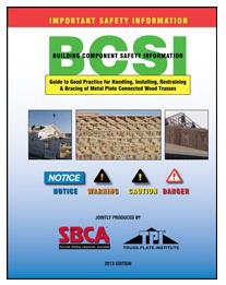
A good reference related to truss repairs for new truss construction is the Building Component Safety Information (BCSI) booklet jointly produced by SBCA and TPI. Section B5 of the BCSI booklet, which is also available as a stand-alone summary sheet, covers Truss Damage, Jobsite Modifications & Installation Errors. This field-guide document describes the steps to take when a truss at the jobsite is damaged, altered or improperly installed, common repair techniques, and the information to provide to the truss manufacturer when a truss is damaged, which will assist in the repair process.
The next easiest truss type to repair is recent construction, where the trusses were constructed recently enough that: a) the truss plates are easy to identify, and b) the truss design drawings may even still be available. In these cases, design professionals other than the original truss Designer may be contacted to repair the trusses. For some types of repairs, the design professional can work off the truss design drawing to design the repair. Other times it might be necessary to model and analyze the truss using structural design software; alternatively, a truss manufacturer can be contacted to model the truss in their truss design software for a fee.
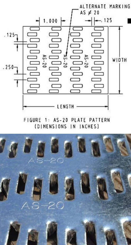
Often, the design professional wants to know the design values for the truss plates that were used to construct the truss. If there are truss design drawings available, they will indicate which truss plates were used in the design, and then the truss plate manufacturer can be contacted for more information. It is also easy to search for the truss plate code reports online (for instance, check icc-es.org). If no truss design drawing is available, there is still a way to identify the truss plates. Currently, there are only five major truss plate manufacturers in the United States, and they are listed on the Truss Plate Institute website. That makes identification of the truss plates used in recently constructed trusses easier because all of the current manufacturers’ plates will have markings that are described in their code reports. (Note that there are also a couple of truss manufacturers in the U.S. that manufacture their own truss plates.)
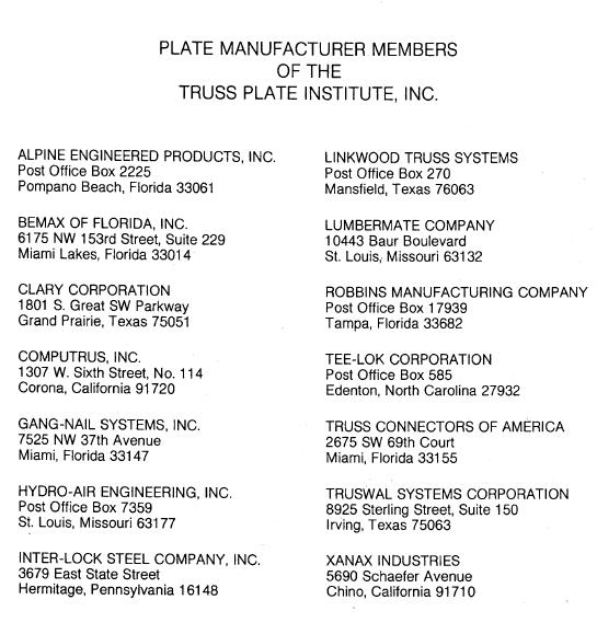
Finally, the most challenging type of trusses for truss repairs are those found in older buildings. Design professionals involved in these types of repair often aren’t sure where to start. Truss design drawings are often not available, and the act of trying to identify the truss plate manufacturer is challenging at best, unsuccessful at worst. As a point of reference, there were 14 truss plate manufacturers that were TPI members in 1987 (see image below), and only one of those companies is still in the current list of five companies. Therefore, the truss plates found in a truss built around 1987 will be difficult to identify. One option is to contact TPI and see if they can point you in the right direction.
Simple vs. Complex Repairs
Another way to break down truss repairs is to divide them into easy and challenging repairs. People often ask for “standard” truss repair details. Unfortunately, standard details only address the simplest types of repair; and those usually aren’t the types of repair that are asked about. Details simply cannot cover the wide range of truss configurations and every type of repair situation.
With the exception of simple repairs, most truss repairs rely heavily on the judgment and experience of the design professional doing the repair. And because there are not entire textbooks devoted to truss repair (that I am aware of, anyway), Designers must pull from a variety of resources, both to learn more about truss repair and to design the repair. For repairs using plywood or OSB gussets, the APA Panel Design Specification is a must-have reference. Some people prefer to use dimension lumber scabs for their repairs, whenever possible, simply because they are more familiar with dimension lumber (and the NDS) than they are with Plywood/OSB or the APA Panel Design Specification.
Next, the fasteners for the repair must be selected and the allowable loads determined. For nail design values, I am a big fan of the American Wood Council’s Connection Calculator, which provides allowable nail shear values for just about any combination of main and side members that you can think of, including OSB and plywood side members – particularly handy for truss repairs. For more complex repairs, and especially repairs involving higher forces, an excellent fastener choice is a structural wood screw such as our Strong-Drive® SDS or SDW screws. When I worked in the R&D department at Simpson Strong-Tie, a frequently asked question was whether we had double-shear values for our SDS screws. The questions always seemed to come from Designers who wanted them for truss repairs. Fortunately, we do have double-shear values for our SDS screws.. You can find them on page 319 of our Fastening catalog.
The Strong-Drive SDW screw was developed after the SDS screw, and while there are currently no double-shear values for the SDW, it is still another good option for repairs.
Fire-Damaged Trusses and Truss Collapses
These situations are in a category by themselves because they go beyond even the most complex repairs involving a major modification to the truss. The biggest difference is that the latter case involves mostly known facts and perhaps some conservative assumptions, whereas damage due to fire or collapse includes many unknowns. Most of the truss Designers I have spoken to about truss damage due to fire or truss collapse often recommend replacement of the trusses rather than repair because it is usually too difficult to quantify the damage to the lumber and/or joints. In fires, there can be “hidden” damage due to the sustained high temperatures, while the truss appears to have no visible damage. Likewise, in a truss collapse, not only may there be too many breaks in the trusses involved in the collapse, but there may also be trusses that suffered severe stresses during the collapse and have damage that is not visible. To attempt a repair in either of these cases often requires an inspection at the jobsite, and the result may still end up being replacement of some or all of the trusses. Therefore, the cost of a full-blown inspection should be weighed against the cost of replacing the trusses.
The Structural Building Components Association website has a page with information pertaining to fire issues. It includes a couple of documents related to fire damage that are worth checking out.
Beyond the Blog: Where to Get More Truss Repair Information
The best bet for getting practical design information related to truss repairs is to keep an eye out for short courses, workshops or seminars. ASCE has hosted a Truss Repair Seminar (Evaluating Damage and Repairing Metal Plate Connected Wood Trusses) in the past and may very well offer something like it again. Virginia Tech recently hosted a short course on Advanced Design Topics in Wood Construction Engineering, which included a section on Wood Truss Repair Design Techniques.
What other references or resources for truss repair do you use? Are there any upcoming truss repair courses that you know of? Please let us know in the comments below!
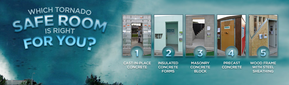
Which Tornado Saferoom is Right for You?
There certainly seems to be increased awareness of the potential for damage and injury from tornadoes these days. Recent information published by the Federal Emergency Management Agency (FEMA) and the Federal Alliance for Safe Homes (FLASH) help explain that. This increased awareness has led to a growing interest in tornado shelters for protection of life and property.
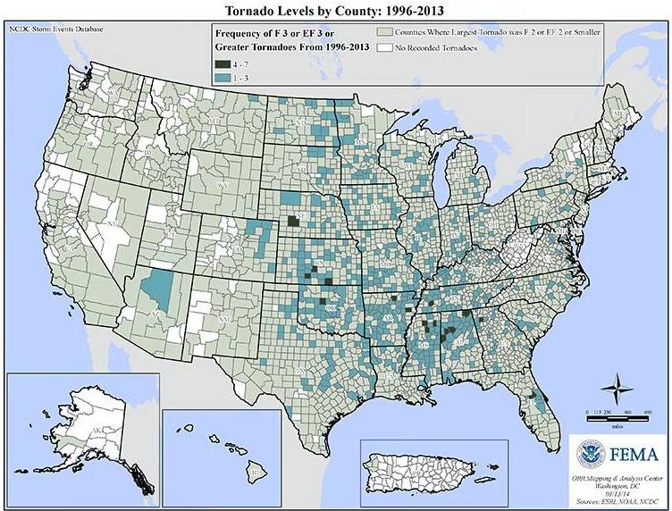
This FEMA graphic shows that most areas of the United States have been affected by a tornado at some point since 1996, and many have been affected by one or more strong tornadoes (EF3 or greater).
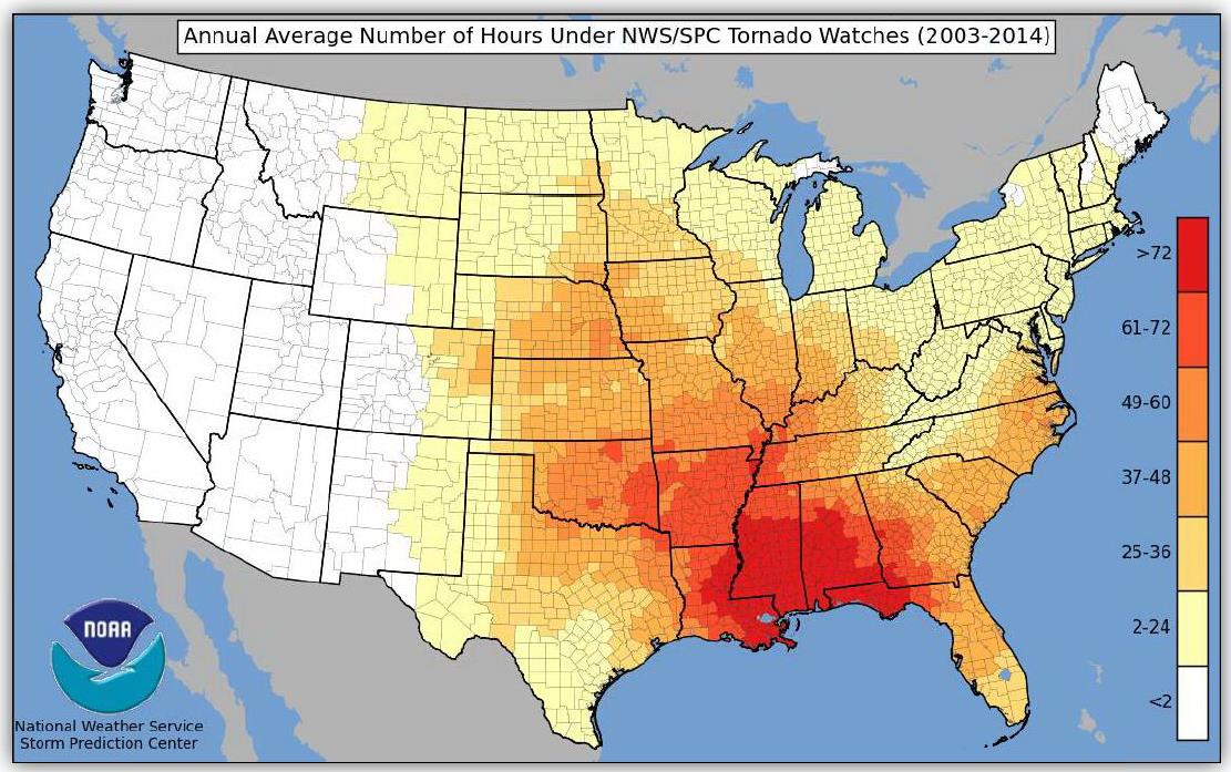
Living in North Texas near the Simpson Strong-Tie manufacturing plant in McKinney, Texas, I know all too well the sinking feeling of hearing the tornado sirens and turning on the TV to find you are under a tornado watch. FLASH recently published a graphic developed by the National Weather Service that shows the large number of U.S. counties that have been under a tornado watch between 2003-2014, and the high number of warnings that some counties experienced.
Other than moving to an area that has fewer tornadoes, one of the best ways to protect your family and at least have more peace of mind during tornado season is to have a tornado shelter or safe room. These structures are designed and tested to resist the highest winds that meteorologists and engineers believe occur at ground level during a tornado and the debris that is contained in tornado winds.
Tornado shelters can be either pre-fabricated and installed by a specialty shelter manufacturer, or can be site-built from a designed plan or pre-engineered plan. A good source for information on pre-fabricated shelters is the National Storm Shelter Association, a self-policing organization that has strict requirements for the design, testing and installation of its members’ shelters.
FEMA publishes a document, P-320, Taking Shelter from the Storm, that provides good information on safe rooms in general, as well as several pre-engineered plans for tornado safe rooms.
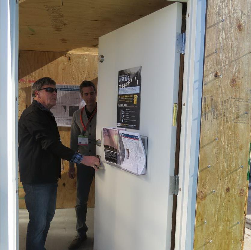
To highlight the different types of safe rooms covered by FEMA P-320, FEMA, FLASH and the Portland Cement Association (PCA) sponsored an exhibit at January’s International Builder’s Show. The exhibit was called the “Home Safe Home Tornado Saferoom Showcase.” It featured six different types of saferooms that builders could incorporate into the homes they build. Simpson Strong-Tie and the American Wood Council collaborated to build a wood frame with steel sheathing safe room meeting the FEMA P-320 plans. Other safe rooms shown at the exhibit included pre-cast concrete and pre-manufactured steel shelters manufactured by NSSA members, and reinforced CMU, ICF cast-in-place concrete and aluminum formed cast-in-place concrete built to FEMA P-320 plans.
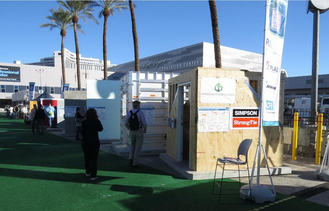
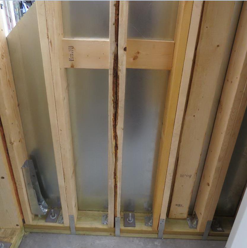
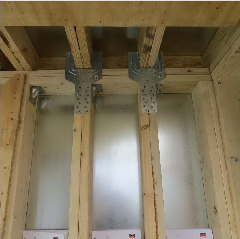
Simpson Strong-Tie staff in McKinney, Texas, constructed the wood frame/steel sheathing safe room in panels and shipped it to the show. It was built from locally sourced lumber, readily available fasteners and connectors and sheets of 16 ga. steel (which we happen to keep here at the factory). It had cut-away sheathing at the corners to show the three layers of sheathing needed. Our message to builders was that this type of shelter would be the easiest for their framers to build on their sites.
The sponsors of the exhibit took advantage of the variety of safe rooms in one place to film a video series, “Which Tornado Safe Room is Right for You?” The videos are posted at the FLASH StrongHomes channel on YouTube. The series provides comparative information on cast-in-place, concrete block masonry, insulated concrete forms, precast concrete and wood-frame safe rooms, with the goal of helping consumers to better understand their tornado safe room options.
“Today’s marketplace offers an unprecedented range of high-performing, affordable options to save lives and preserve peace of mind for the millions of families in the path of severe weather,” said FLASH President and CEO Leslie Chapman-Henderson. “These videos will help families understand their options for a properly built safe room that will deliver life safety when it counts.”
FLASH released the videos earlier this month as part America’s PrepareAthon!, a grassroots campaign to increase community emergency preparedness and resilience through hazard-specific drills, group discussions and exercises. The overall goal of the program is to get individuals to understand which disasters could happen in their community, know what to do to be safe and mitigate damage from those disasters, take action to increase their preparedness, and go one step farther by participating in resilience planning for their community. Currently, the program focuses on preparing for the disasters of tornadoes, hurricanes, floods, wildfires, earthquakes and winter storms.
Do you know what the risk of disasters is in your community? If you are subject to tornado risk, would you like to build your own safe room, have one built to pre-engineered plans or buy one from a reputable manufacturer? Let us know in the comments below.