Revisiting Spanning the Gap

Three years ago, we created this blog post based on a technical support question we often receive about allowable fastener loads for ledgers to wood framing over gypsum board. Given that this is still a frequent question and a relevant topic, we decided to revisit the post and update it.

Drywall. Wall board. Sheetrock. Sackett Board? A product called Sackett Board was invented in the 1890s, which was made by plastering within wool felt paper. United States Gypsum Corporation refined Sackett Board for several years until 1916, when they developed a new method of producing boards with a single layer of plaster and paper. This innovation was eventually branded SHEETROCK®. More details about the history of USG can be found here.

No matter what you call it, gypsum board is found in almost every type of construction. Architects use it for sound and fire ratings, while structural engineers need to account for its weight in our load calculations. A common technical support question we receive is for allowable fastener loads for ledgers to wood framing over gypsum board.
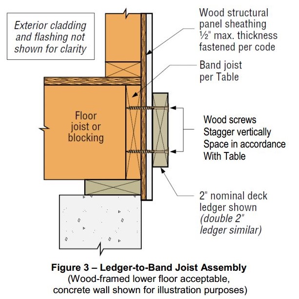
Ledger over Gypboard

One method to evaluate a fastener spanning across gypsum board is to treat the gypsum material as an air gap. Technical Report 12, General Dowel Equations for Calculating Lateral Connection Values, is published by the American Wood Council.
Technical Report 12
Technical Report 12

TR12 has yield limit equations that allow a designer to account for a gap between the main member and side member of a connection. With a gap of zero (g=0), the TR12 equations provide the same results as the NDS yield limit equations.

Technical Report 12 Yield Limit Equations[1]
Technical Report 12 Yield Limit Equations
The equations are fairly complex, but it should be intuitive that the calculated fastener capacity decreases with increasing gap. Engineers are often surprised to see a 40, 50, even 60% drop in fastener capacity with one layer of 5/8” gypsum board. So what else can you do?

Testing, of course! In So, What’s Behind a Screw’s Allowable Load? I discussed the methods used to load rate a proprietary fastener such as the Simpson Strong-Tie® Strong-Drive® SDS or SDW screws. To recap, ICC-ES Acceptance Criteria for Alternate Dowel Type Fasteners, AC233, allows you to calculate and do verification tests, or load rate based on testing alone. We develop our allowable loads primarily by testing, as the performance enhancing features and material optimizations in our fasteners are not addressed by NDS equations.

So to determine the performance of a fastener installed through gypsum board, we tested the fastener through gypsum board. This is easier to do if you happen to have a test lab with a lot of wood and fasteners in it. We did have to run down to the local hardware store to pick up gypsum board for the testing.
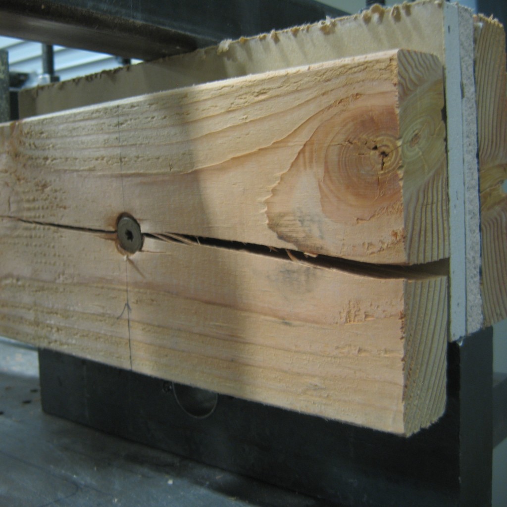
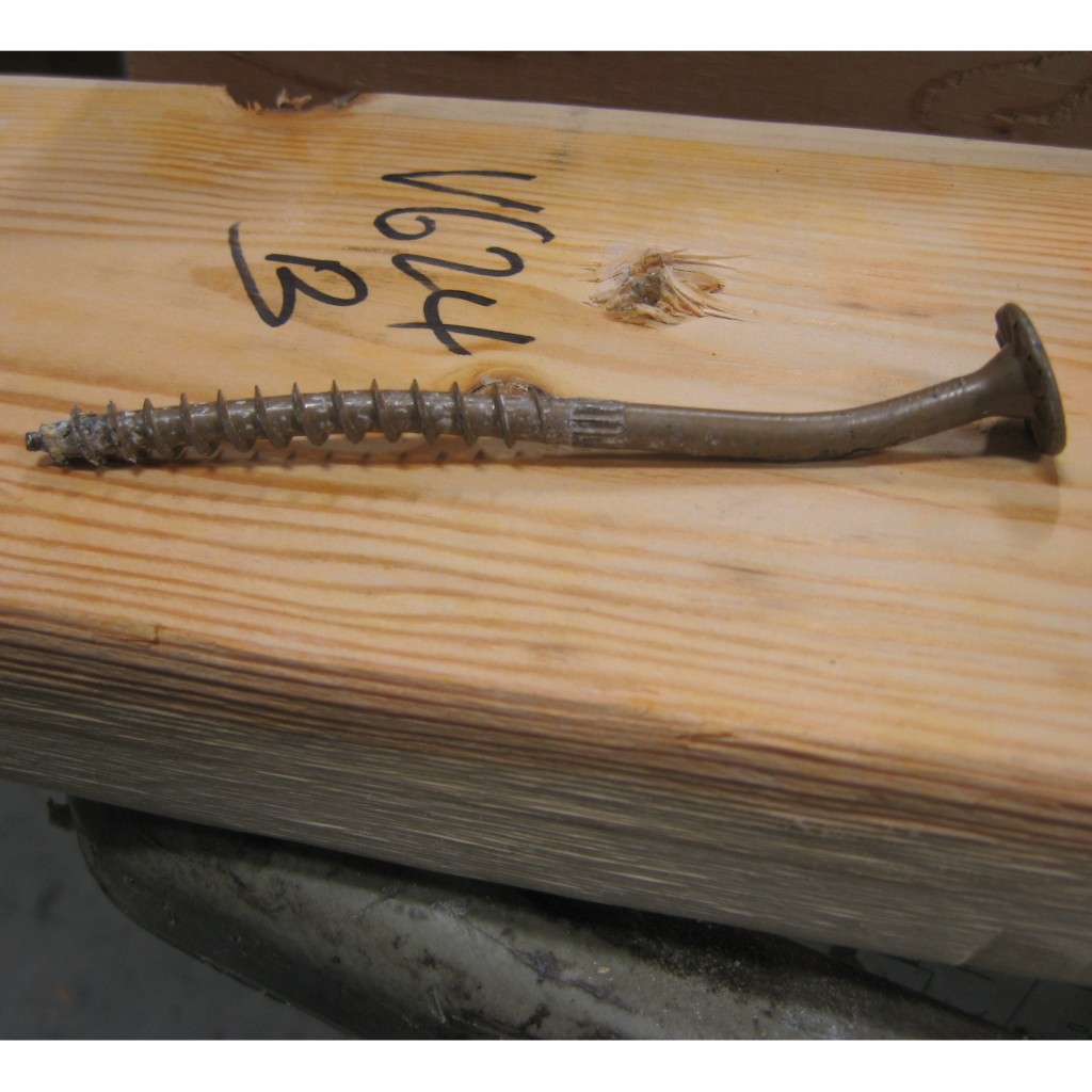
SDWS Over 2 Layer Gypboard
SDWS-Over-2-Layer-Gypboard-Failure
SDWS Over 2 Layer Gypboard Failure

A full set of allowable loads for Strong-Drive SDWH and SDWS are available on strongtie.com. The information is given as single fastener shear values for engineered design, and also screw spacing tables for common ledger configurations. As much fun as writing spreadsheets to do the Technical Report 12 calculations is, having tabulated values based on testing is much easier.

Fastening Systems

In the fastener marketplace, Simpson Strong-Tie stands apart from the rest. Quality and reliability is our top priority.

Why You Should Specify Stainless-Steel Screw Anchors When Designing for Corrosive Environments

I was driving under a concrete bridge one nice clear day in Chicago, and I happened to look up to see rusted rebar exposed below a concrete bridge. My beautiful wife, who is not a structural engineer, turned to me and asked, “What happened to that bridge?” I explained that there are many reasons why spalling occurs below a bridge. One common reason is the expansion of steel when it rusts or corrodes.

Continue Reading

Decrypting Cold-Formed Steel Connection Design

As published in STRUCTURE magazine, September 2016. Written by Randy Daudet, P.E., S.E., Product Manager at Simpson Strong-Tie.  Re-posted with permission. 

One of the world’s greatest unsolved mysteries of our time lies in a courtyard outside of the Central Intelligence Agency (CIA) headquarters in Langley, Virginia. It’s a sculpture called Kryptos, and although it’s been partially solved, it contains an inscription that has puzzled the most renowned cryptanalysts since being erected in 1990. Meanwhile, in another part of the DC Beltway about 15 miles to the southeast, another great mystery is being deciphered at the American and Iron Institute (AISI) headquarters.Continue Reading

New Moment-Resisting Post Base

Jhakak Vasavada

Jhalak Vasavada is currently a Research & Development Engineer for Simpson Strong-Tie. She has a bachelor’s degree in civil engineering from Maharaja Sayajirao (M.S.) University of Baroda, Gujarat, India, and a master’s degree in structural engineering from Illinois Institute of Technology, Chicago, IL. After graduation, she worked for an environmental consulting firm called TriHydro Corporation and as a structural engineer with Sargent & Lundy, LLC, based in Chicago, IL. She worked on the design of power plant structures such as chimney foundations, boiler building and turbine building steel design and design of flue gas ductwork. She is a registered Professional Engineer in the State of Michigan.

At Simpson Strong-Tie, we strive to make an engineer’s life easier by developing products that help with design efficiency. Our products are designed and tested to the highest standards, and that gives structural engineers the confidence that they’re using the best product for their application.

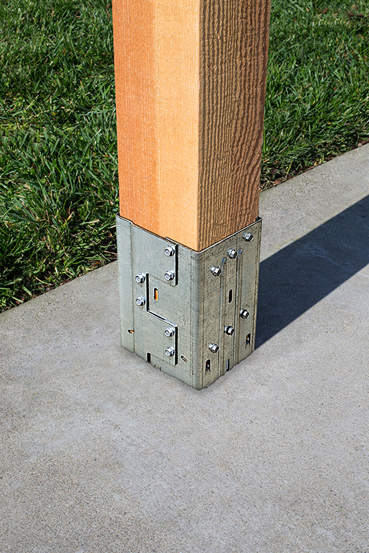
Installed MPBZ
Figure 1: Installed MPBZ

Having worked in the design industry for almost a decade, I can attest that having a catalog where you can select a product that solves an engineer’s design dilemma can be a huge time- and money-saving tool. Design engineers are always trying to create efficient designs, although cost and schedule are always constraints. Moment connections can be very efficient — provided they are designed and detailed correctly. With that in mind, we developed a moment post base connector that can resist moment in addition to download, uplift and lateral loads. In this post, I would like to talk about moment-resisting/fixed connections for post bases and also talk about the product design process.

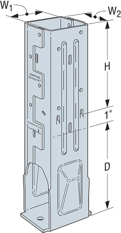
Figure 2. MPB44Z Graphic

Lateral forces from wind and seismic loads on a structure are typically resisted by a lateral-force-resisting system. There are three main systems used for ordinary rectangular structures: (a) braced frames, (b) moment frames and (c) shearwalls. Moment frames resist lateral forces through bending in the frame members. Moment frames allow for open frames by eliminating the need for vertical bracing or knee bracing. Moment resistance or fixity at the column base is achieved by providing translational and rotational resistance. The new patent-pending Simpson Strong-Tie® MPBZ moment post base is specifically designed to provide moment resistance for columns and posts. An innovative overlapping sleeve design encapsulates the post, helping to resist rotation at its base.

The allowable loads we publish have what I call “triple backup.” This backup consists of Finite Element Analysis (FEA), code-compliant calculations and test data. Here are descriptions of what I mean by that.

Finite Element Analysis Confirmation

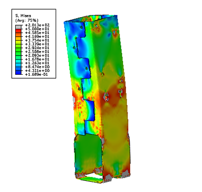
Once a preliminary design for the product is developed, FEA is performed to confirm that the product behaves as we expect it to in different load conditions. Several iterations are run to come up with the most efficient design.

Figure 3. FEA Output of Preliminary MPB Conceptual Design

Code-Compliance Calculations

Load calculations are prepared in accordance with the latest industry standards. The connector limit states are calculated for the wood-post-to-MPBZ connection and for MPBZ anchorage in concrete. Steel tensile strength is determined in accordance with ICC-ES AC398 and AISI S100-07. Wood connection strength is determined in accordance with ICC-ES AC398 and AC13. Fastener design is analyzed as per NDS. SDS screw values are analyzed using known allowable values per code report ESR-2236. The available moment capacity of the post base fastened to the wood member is calculated in accordance with the applicable bearing capacity of the post and lateral design strength of the fasteners per the NDS or ESR values. Concrete anchorage pull-out strength is determined in accordance with AC398.

Test Data Verification

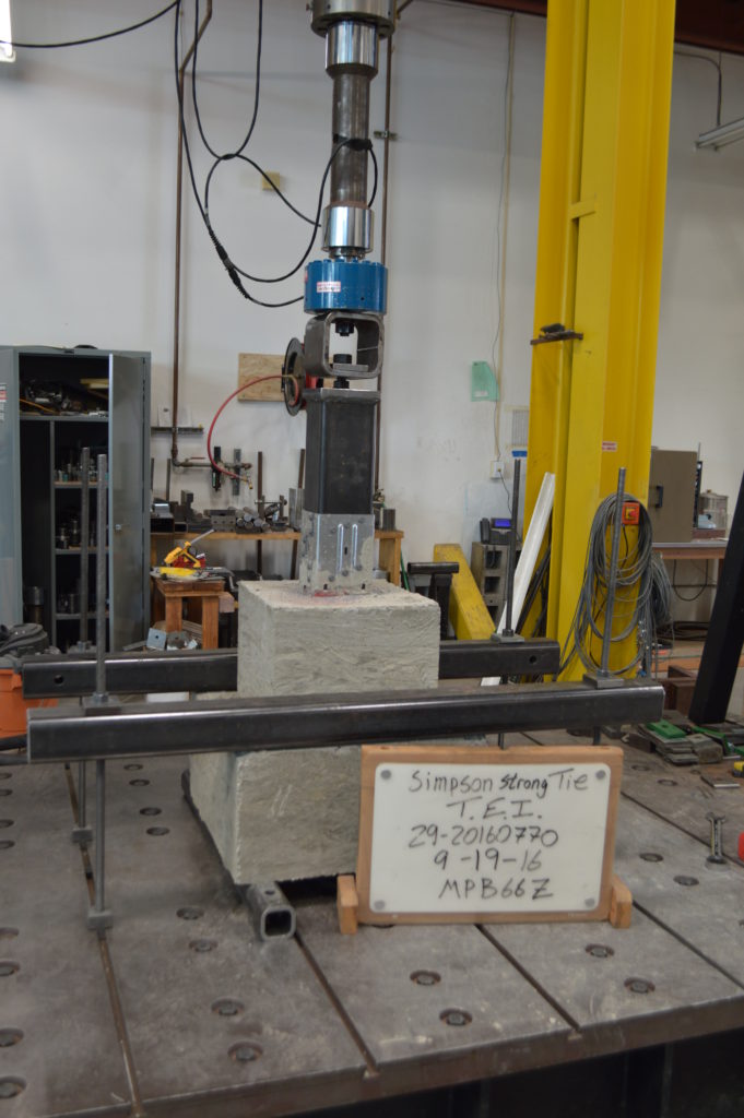
The moment post base is tested for anchorage in both cracked and uncracked concrete in accordance with ICC-ES AC398.

Figure 4. Uplift Test Setup

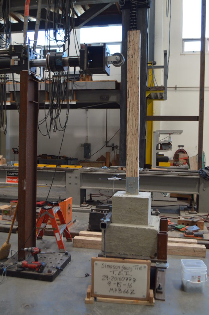
The moment post base assembly is tested for connection strength in accordance with ICC-ES AC13.

Figure 5: Moment (induced by lateral load application) Test Set Up

The assembly (post and MPBZ) is tested for various loading conditions: download, uplift and lateral load in both orthographic directions and moment. Applicable factor(s) of safety are applied, and the controlling load for each load condition is published in the Simpson Strong-Tie Wood Construction Connectors Catalog.

Now let’s take a look at a sign post base design example to see how the MPBZ data can be used.

Design Example:

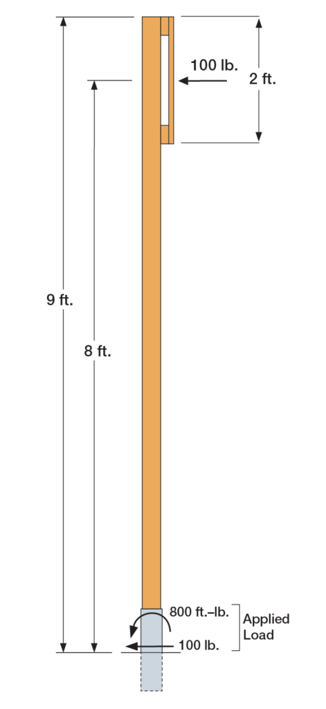
Figure 6: Sign Post Base Design Example

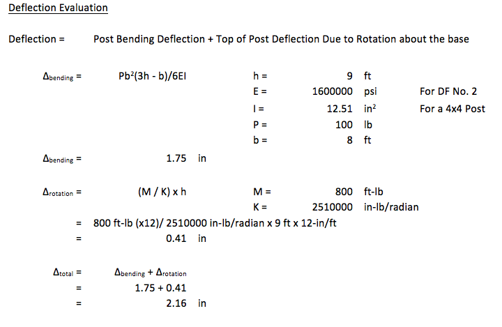
The MPB44Z is used to support a 9ʹ-tall 4×4 post with a 2ʹ x 2ʹ sign mounted at the top. The wind load acting on the surface of the sign is determined to be 100 lb. The MPB44Z is installed into concrete that is assumed to be cracked.

  • The design lateral load due to wind at the MPB44Z is 100 lb.
  • The design moment due to wind at the MPB44Z is (100 lb.) x (8 ft.) = 800 ft.-lb.
  • The Allowable Loads for the MPB44Z are:
    • Lateral (F1) = 1,280 lb.
    • Moment (M) = 985 ft.-lb.
  • Simultaneous Load Check:
    • 800/985 + 100/1,280 = 0.89. This is less than 1.0 and is therefore acceptable.

mpbz-deflection-evaultion

We are very excited about our new MPBZ! We hope that this product will get you excited about your next open-structure design. Let us know your thoughts by providing comments here.

Considerations for Designing Anchorage in Proximity to Abandoned Anchor Holes

danharmon.headshot.finalThis week’s post comes from Dan Harmon, an R&D engineer for Simpson Strong-Tie’s Infrastructure-Commercial-Industrial (ICI) group. Dan specializes in post-installed concrete anchor design and spent a decade managing Simpson’s anchor testing lab, where he developed extensive knowledge of anchor behavior and performance. He has a Bachelor of Science in mechanical engineering from the University of Illinois Urbana-Champaign.

Designers and engineers can spend hundreds of hours on detailed drawings of structures, but there are often conditions and coordination that can change well-planned details and drawings. As we all know, paper and reality don’t always agree. Anchorage locations can move as a result of unforeseen circumstances such as encountering reinforcing bars in an existing concrete slab or interference between different utility trades.

With post-installed anchors, one particular jobsite change may require abandoning a hole that has been drilled, leaving the final anchor location adjacent to the abandoned hole. When a hole for an anchor is drilled but never used, it essentially creates a large void in the concrete. Depending on where this void is located in relation to an installed anchor, there is potential for the capacity of that anchor to be reduced. To give guidance on this situation to specifiers, users and contractors, Simpson Strong-Tie conducted a large series of tests in their ISO 17025–accredited Anchor Systems Test Lab in Addison, Illinois.

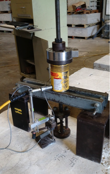
To evaluate the effect of abandoned holes located adjacent to post-installed anchors, we performed tension tests meeting the requirements of ASTM E488-15 (see Figure 1). A variety of anchor types with common diameters were tested:

  • Drop-in anchors (1/2″ and 3/4″ diameter)
  • Wedge-type anchors (1/2″ and 3/4″ diameter)
  • Concrete screws (1/2″ diameter)
  • Adhesive anchors with threaded rod (1/2″ diameter)
Figure 1: Common Unconfined Tension Test Set-Up per ASTM E488-15

Each anchor type and diameter was tested under five different conditions:

  • No abandoned hole near the installed anchor. This is considered the reference condition to which other tests are to be compared.
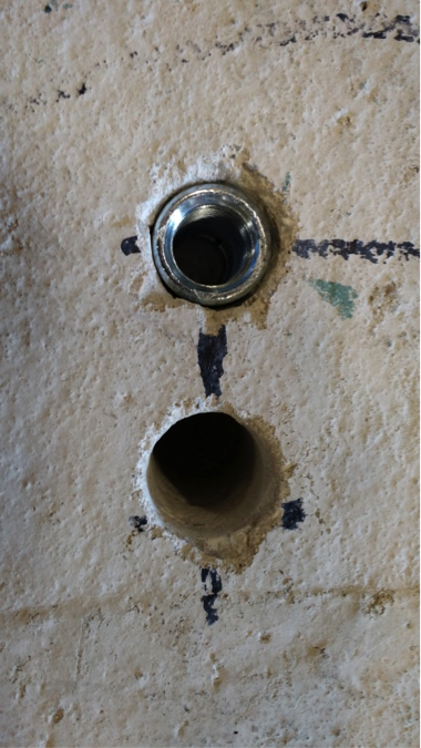
  • One abandoned hole at a distance of two times the hole diameter (2d) away from the installed anchor. See Figure 2.
  • One abandoned hole at a distance of four times the hole diameter (4d) away from the installed anchor.
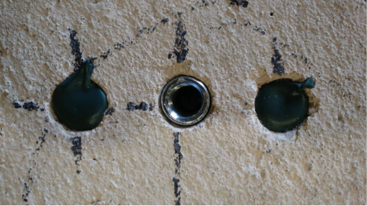
  • Two abandoned holes, each at a distance of two times the hole diameter (2d) away from the installed anchor. In test conditions with two holes, the holes were located on either side of the installed anchor, approximately 180º from each other. See Figure 3.
  • Two abandoned holes, each at a distance of two times the hole diameter (2d) away from the installed anchor, with the holes refilled with a concrete anchoring adhesive that was allowed to cure fully prior to testing. See Figure 4.
Figure 2: Drop-In Anchor with a Single Hole at a Distance of 2d
Figure 3: Drop-In Anchor with Two Holes at a Distance of 2d
Figure 4: Drop-In Anchor with Two Holes, Filled with Anchoring Adhesive, at a Distance of 2d

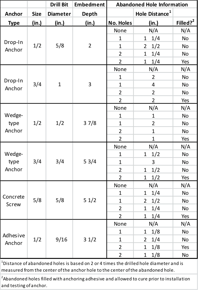
This test program is summarized in Table 1. In all cases, the abandoned hole was of the same diameter and depth as the hole prescribed for the installed anchor.

Table 1. Summary of Test Program

Five tests for each anchor under each condition were tested, and the mean and coefficient of variance of each data set were calculated. These calculated values were used to compare the different conditions.

Across the different anchor types and diameters, the test results showed a number of general rules that held true.

Summary Results

Abandoned holes that are 2” or more away from the anchor have little to no effect on the tension performance of the anchor. Compared to the reference condition with no abandoned hole near the anchor, conditions where the abandoned hole was sufficiently far away were found to be essentially equivalent. This equivalence held true even for anchor types that create expansion forces (drop-in and wedge-type anchors) during their installation.

Two abandoned holes have the same effect on performances as one, regardless of distance from the anchor. This testing showed that adding a second abandoned hole near an installed anchor did not adversely affect tension performance in a significant way. Even within distances of 2 inches, performance did not drop substantially – if at all – in conditions involving two abandoned holes as compared to one.

Filling abandoned holes with an anchoring adhesive prior to installation of the anchor improves performance. In all cases tested, filling abandoned holes with adhesives resulted in increased performance compared to leaving the holes empty. In a majority of cases, performance with filled holes was equivalent to performance in the reference condition regardless of the distance from the anchor.
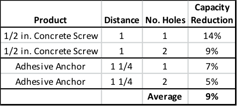
When the abandoned hole is more than two times the drilled hole diameter but less than 2″from the anchor – and left unfilled – the testing showed a loss in performance. Not surprisingly, the degree of that loss was dependent on the type of anchor. Table 2 shows the capacity reduction compared to the reference condition in testing with expansion anchors. Table 3 shows the same results for concrete screws and adhesive anchors. Conservative suggested performance reductions in these conditions would be 20% for expansion anchors and 10% for concrete screws and adhesive anchors.

Table 2: Performance Reduction for Expansion Anchors
Table 3: Performance Reduction for Concrete Screws and Adhesive Anchors

In an ideal world, the engineer’s designs could be followed at all times at the jobsite. But we don’t live in an ideal world. Good engineering judgment is needed in situations where variation is required, and having data to support those decisions is always helpful. In the case of abandoned holes near post-installed anchors, it’s Simpson Strong-Tie’s hope that this testing provides additional guidance for the designer, inspector, and jobsite worker.


Q&A: Best Practices for FRP Strengthening Design

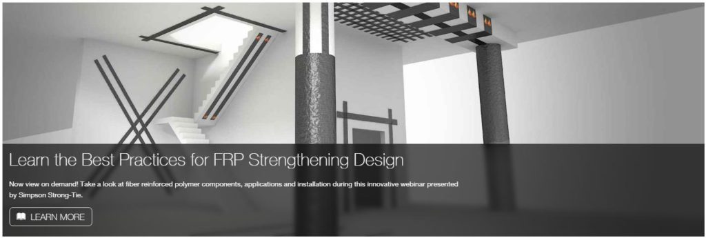
frp-design-banner

On December 1, 2016, Simpson Strong-Tie hosted a webinar titled “The Design Fundamentals of FRP Strengthening” in which Justin Streim, P.E. – one of our Field Engineers – and I discussed the best practices for fiber-reinforced polymer (FRP) strengthening design. The webinar examines FRP components, applications and installation. It also features an example of the evaluation that went into a flexural-beam-strengthening design and discusses the assistance and support Simpson Strong-Tie Engineering Services offers from initial project assessment to installation. Watch the on-demand webinar and earn PDH and CEU credits here.

During the live webinar, we had the pleasure of presenting to more than 1,500 engineers who asked nearly 300 questions during the Q&A session. Here is a curated selection of Q&A from that session:

q-a-graphic

Can you discuss the flexural strengthening for reinforced masonry walls?

Out-of-plane flexural strengthening can be provided with FRP on the required face of wall. In-plane (or shear wall type) flexural strengthening can also be provided with vertical FRP strips near the ends of walls.

In general, by what percentage can FRP solutions increase the strength of existing concrete shearwalls?

This really depends on the existing wall, but we have seen strength increases of 22% in our testing of one layer of glass fabric installed on 8″ thick ungrouted CMU shearwall.

How does FRP compete in terms of cost? It seems like a cost-prohibitive solution compared to other remediation techniques in the absence of other limiting factors (space limitations, etc.).

FRP may be expensive on a cost/SF basis. However, if you compare it with the materials and labor involved in section enlargement or demolishing parts of buildings, it becomes cost effective. FRP installations are also not unsightly like bolted steel plates or wide flange members slung under concrete slabs/beams.

Who designs the FRP system: Simpson Strong-Tie or the Structural Designer?

The Simpson Strong-Tie Engineering Services group provides the FRP design on most projects, but we have also worked with the engineer on record (EOR) to check their FRP design on projects.

Are there any deformation compatibility issues between carbon fiber or glass and existing reinforcing bar that need to be accounted for in design? Is long-term creep similar to that seen with reinforcing bar?

CFRP and GFRP have different elastic moduli from each other and from steel. When designing an FRP strengthening solution, these differences must be taken into account. For flexural applications, the FRP should be designed to fail from debonding after the internal rebar begins to yield. Creep is taken into account in design equations through reduction factors and stress checks.

Will ACI 440 be updated to include the use of FRP with post-tensioned beams (i.e., unbonded tendons)? Does Simpson Strong-Tie do all stress checks based on gross section properties when total stress is < 12sqrtf’c?

Yes, there is an ACI 440 committee working on including an unbonded PT section in ACI 440.2R. We will work with the EOR to determine what section properties are most appropriate for the specific member being evaluated.

Can you increase deflection limits with FRP?

While FRP does help to limit deflection in members, members with deflection issues are not typically candidates for FRP repair. Prestressed laminates as used in Europe would be a better solution for a member with deflection issues. We do not currently offer prestressed laminates but may in the future.

Does an aesthetic coating interfere with bridge inspection? What is inspection looking for? Delamination or other defects?

A coating could interfere with a visual inspection of the FRP surface. A visual inspection can reveal changes in color, debonding, peeling, blistering, cracking, crazing, deflections, indications of reinforcing-bar corrosion, and other anomalies. In addition, ultrasonic, acoustic sounding (hammer tap) and thermographic tests may indicate signs of progressive delamination. ACI 440 and AC 178 have extensive special inspection recommendations.

Learn more: Webinar – Introducing Fabric-Reinforced Cementitious Matrix (FRCM)

In this free webinar we dive into some very important considerations including the latest industry standards, material properties and key governing limits when designing with FRCM.

Continuing education credits will be offered for this webinar.
Participants can earn one professional development hour (PDH) or 0.1 continuing education unit (CEU).


For complete information regarding specific products suitable to your unique situation or condition, please visit strongtie.com/css or call your local Simpson Strong-Tie RPS specialist at (800) 999-5099.


Q&A: Best Practices for FRP Strengthening Design

frp-design-banner
On December 1, 2016, Simpson Strong-Tie hosted a webinar titled “The Design Fundamentals of FRP Strengthening” in which Justin Streim, P.E. – one of our Field Engineers – and I discussed the best practices for fiber-reinforced polymer (FRP) strengthening design. The webinar examines FRP components, applications and installation. It also features an example of the evaluation that went into a flexural-beam-strengthening design and discusses the assistance and support Simpson Strong-Tie Engineering Services offers from initial project assessment to installation. Watch the on-demand webinar and earn PDH and CEU credits here.
During the live webinar, we had the pleasure of presenting to more than 1,500 engineers who asked nearly 300 questions during the Q&A session. Here is a curated selection of Q&A from that session:
q-a-graphic
Can you discuss the flexural strengthening for reinforced masonry walls?
Out-of-plane flexural strengthening can be provided with FRP on the required face of wall. In-plane (or shear wall type) flexural strengthening can also be provided with vertical FRP strips near the ends of walls.
In general, by what percentage can FRP solutions increase the strength of existing concrete shearwalls?
This really depends on the existing wall, but we have seen strength increases of 22% in our testing of one layer of glass fabric installed on 8″ thick ungrouted CMU shearwall.
How does FRP compete in terms of cost? It seems like a cost-prohibitive solution compared to other remediation techniques in the absence of other limiting factors (space limitations, etc.).
FRP may be expensive on a cost/SF basis. However, if you compare it with the materials and labor involved in section enlargement or demolishing parts of buildings, it becomes cost effective. FRP installations are also not unsightly like bolted steel plates or wide flange members slung under concrete slabs/beams.
Who designs the FRP system: Simpson Strong-Tie or the Structural Designer?
The Simpson Strong-Tie Engineering Services group provides the FRP design on most projects, but we have also worked with the engineer on record (EOR) to check their FRP design on projects.
Are there any deformation compatibility issues between carbon fiber or glass and existing reinforcing bar that need to be accounted for in design? Is long-term creep similar to that seen with reinforcing bar?
CFRP and GFRP have different elastic moduli from each other and from steel. When designing an FRP strengthening solution, these differences must be taken into account. For flexural applications, the FRP should be designed to fail from debonding after the internal rebar begins to yield. Creep is taken into account in design equations through reduction factors and stress checks.
Will ACI 440 be updated to include the use of FRP with post-tensioned beams (i.e., unbonded tendons)? Does Simpson Strong-Tie do all stress checks based on gross section properties when total stress is < 12sqrtf’c?
Yes, there is an ACI 440 committee working on including an unbonded PT section in ACI 440.2R. We will work with the EOR to determine what section properties are most appropriate for the specific member being evaluated.
Can you increase deflection limits with FRP?
While FRP does help to limit deflection in members, members with deflection issues are not typically candidates for FRP repair. Prestressed laminates as used in Europe would be a better solution for a member with deflection issues. We do not currently offer prestressed laminates but may in the future.
Does an aesthetic coating interfere with bridge inspection? What is inspection looking for? Delamination or other defects?
A coating could interfere with a visual inspection of the FRP surface. A visual inspection can reveal changes in color, debonding, peeling, blistering, cracking, crazing, deflections, indications of reinforcing-bar corrosion, and other anomalies. In addition, ultrasonic, acoustic sounding (hammer tap) and thermographic tests may indicate signs of progressive delamination. ACI 440 and AC 178 have extensive special inspection recommendations.

Learn more: Webinar – Introducing Fabric-Reinforced Cementitious Matrix (FRCM)

In this free webinar we dive into some very important considerations including the latest industry standards, material properties and key governing limits when designing with FRCM.
Continuing education credits will be offered for this webinar.
Participants can earn one professional development hour (PDH) or 0.1 continuing education unit (CEU).

For complete information regarding specific products suitable to your unique situation or condition, please visit strongtie.com/css or call your local Simpson Strong-Tie RPS specialist at (800) 999-5099.
 

Pile Construction Fasteners – New and Expanded Applications

The majority of Simpson Strong-Tie fasteners are used to secure small, solid-sawn lumber and engineered wood members. However, there is a segment in the construction world where large piles are the norm. Pile framing is common in piers along the coast, elevated houses along the beach, and docks and boardwalks.

While the term “pile” is generic, the piles themselves are not generic. They come in both square and round shapes, as well as an array of sizes, and they vary greatly based on region. The most common pile sizes are 8 inches, 10 inches, and 12 inches, square and round, but they can be found in other sizes. The 8-inch and 10-inch round piles are usually supplied in their natural shape, while 12-inch round piles are often shaped to ensure a consistent diameter and straightness. All piles are preservative-treated.

Historically, the attachment of framing to piles has been done with bolts. This is a very labor-intensive method of construction, but for many years there was no viable fastener alternative. Two years ago, however, Simpson Strong-Tie introduced a new screw, the Strong-Drive® SDWH Timber-Hex HDG screw (SDWH27G), specifically designed for pile- framing construction needs. It can be installed without predrilling and is hot-dip galvanized (ASTM A153, Class C) for exterior applications.

Figure 1 – SDWH27G Lengths

Simpson Strong-Tie tested a number of different pile-framing connections that can be made with the SDWH27G screw. This blog post will highlight some of the tested connections. More information can be found in the following three documents on our website:

  • The flier for the SDWH Timber-Hex HDG screw: F-FSDWHHDG14 found here.
  • The engineering letter for Square Piles found here.
  • The engineering letter for Round Piles found here.

The flier provides product information, and the engineering letters include dimensional details for common pile-framing connections that were tested.

Piles are typically notched or coped to receive a horizontal framing member called a “stringer.” The coped shoulder provides bearing for the stringer and serves as a means of transferring gravity load to the pile. The SDWH27G can be used to fasten framing to coped and non-coped round and square piles.

The connections that we tested can be put into four general groups that include both round and square piles:

  • Two-side framing on coped and non-coped piles
  • One–side framing on coped and non-coped piles
  • Corner framing on coped piles
  • Bracing connections

Additionally, the testing program included four different framing materials in several thicknesses and depths:

  • Glulam
  • Parallam
  • Sawn lumber
  • LSL/LVL

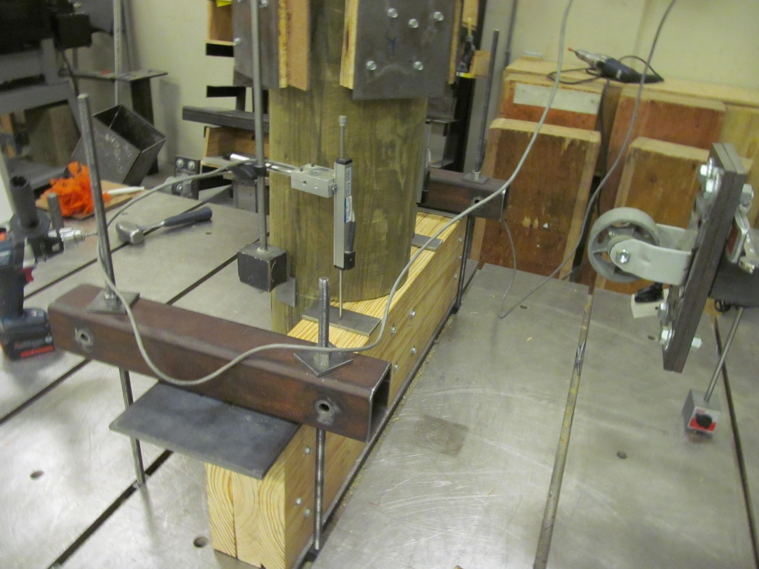
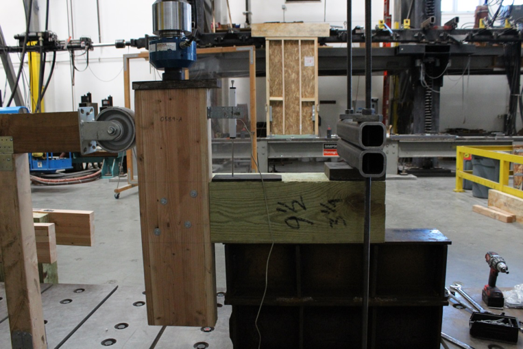
The total testing program included more than 50 connection conditions that represented pile shape and size, framing material and thickness and framing orientation and details. We assigned allowable uplift and lateral properties to the tested connections using the analysis methods of ICC-ES AC13. Figures 2 and 3 show some of the tested assemblies.

Figure 2 – Uplift Test of a 10" Coped Round Pile with a 3-2x10 SYP Stringer
Figure 2 – Uplift Test of a 10″ Coped Round Pile with a 3-2×10 SYP Stringer
Figure 3 – Lateral Test of an 8" Coped Square Pile with a 3.125" Glulam Stringer
Figure 3 – Lateral Test of an 8″ Coped Square Pile with a 3.125″ Glulam Stringer

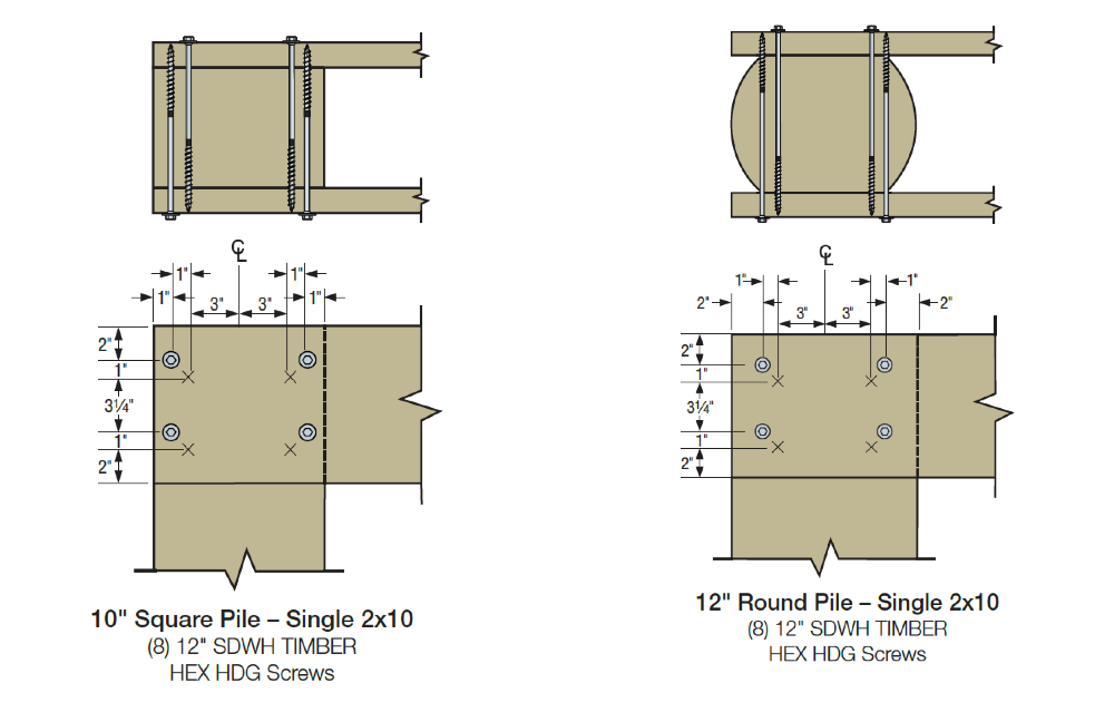
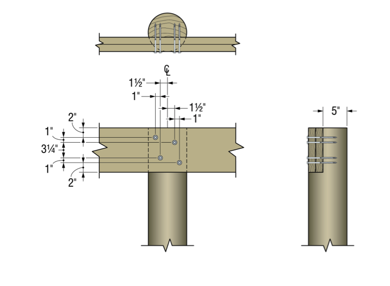
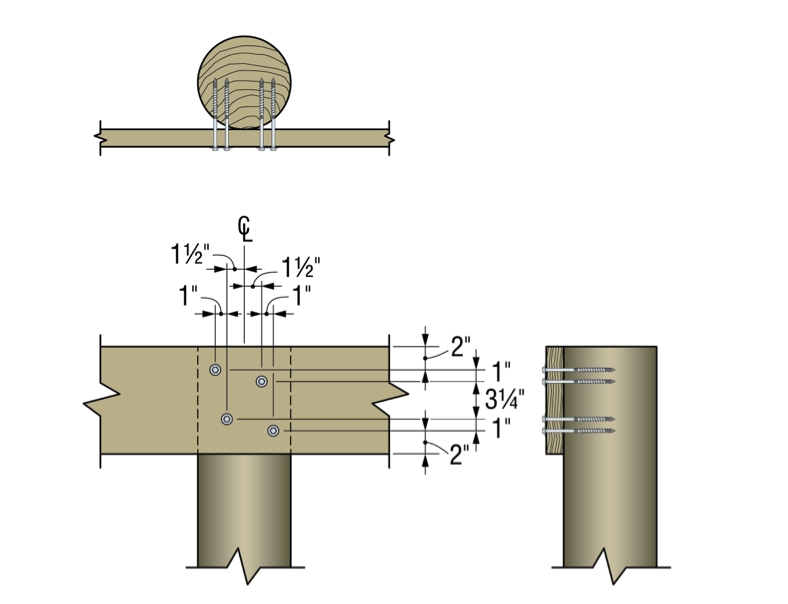
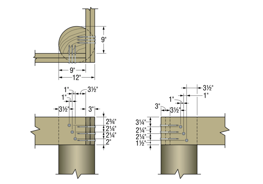
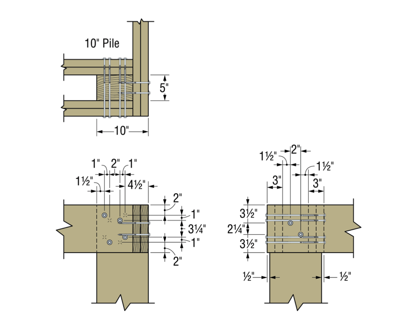
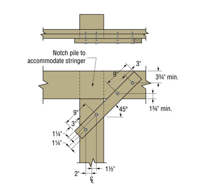
Figures 4 through 9 illustrate some of the connections and details that are presented in the flier and engineering letters.

Some elements of practice are important to the design of pile-framing connections. Some of the basic practices include:

  • For coped connections, the coped section shall not be more than 50% of the cross-section.
  • For coped connections, the coped shoulder should be as wide as the framing member(s).
  • Fastener spacing is critical to the capacity of the connection.
  • When installing fasteners from two directions, lay out the fasteners so that they do not intersect.
Figure 4 – Square and Round Two-Sided Stringers
Figure 5 – Single-Side Stringer with Notched Pile
Figure 6 – Single-Side Stringer with Unnotched Pile
Figure 7 – Round Pile Corner Condition
Figure 8 – Square Pile Corner Condition

In many cases, pile-framing connections use angled braces for extra lateral support. The SDWH27G can be used in these cases too.

Figure 9 – Braced Condition

In the flier and engineering letters previously referenced, you will find allowable loads and specific fastener specifications for many combinations of stringer and pile types and sizes.

What have you seen in your area? Let us know – perhaps we can add your conditions to our list.


New LSSJ Hanger Strengthens Jack Rafter Connections

When our company is considering a new or improved product, we like to start out by talking to our customers first. That’s what we did recently with a connector improvement project for attaching jack rafter hangers in roof framing – and we got lots of feedback!

We heard from installers that they really wanted a hanger that could be easily adjusted in the field for different slopes and skews. We were asked whether we could design a hanger that could be installed after the rafters were already tacked into place to support construction sequencing and retrofit applications. Also, having a hanger that could be installed from one side was a popular time-saving request.

Our Engineering innovation team took all this feedback and closely evaluated our current selection of hangers. After much consideration, the team decided that rather than adapt one of our existing hangers, they would try to  come up with an all-new design that would satisfy our customers’ most pressing needs.

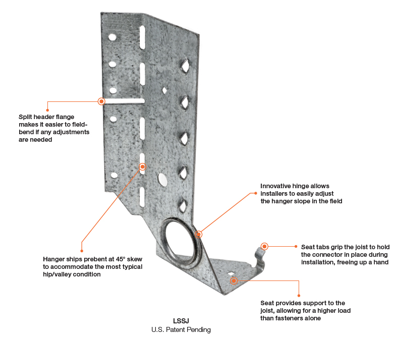
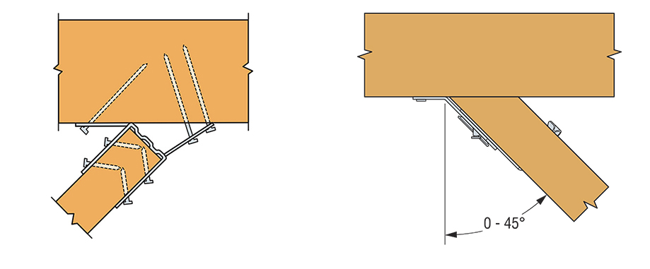
After months of designing and testing prototypes in the lab and in field trials, the answer was yes. The result is our new LSSJ field-adjustable jack hanger. It’s an innovative field-slopeable and field-skewable hanger that features a versatile hinged seat. This new design allows it to be adjusted to typical rafter slopes, with a max slope of 12:12 up or down.

What is a jack hanger and why does it provide a better connection than nails alone? 

There are two basic types of wood roof construction: framed roof construction (stick framing) as shown above, and truss assembly. The main difference is that stick assembly takes place onsite, while trusses are prefabricated and ready to place. In the United States, the number of truss-built roofs versus stick-frame roofs is about two to one. The LSSJ jack hanger is used for stick-frame construction and provides a connection between the jack rafter to either the hip rafter or the valley rafter as shown below.
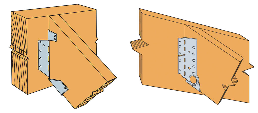
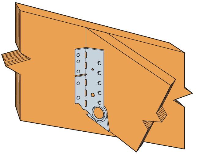
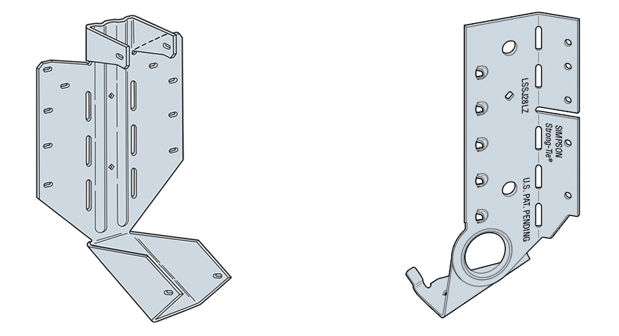
The LSSU hanger connects the jack rafter to the hip rafter
The LSSJ hanger connects the jack rafter to the hip rafter

Connecting a 2X jack rafter to a hip is hardly new. The hardest thing is making a good compound miter cut – something an experienced framer can figure out (and most engineers marvel at). In many parts of the country, these are simply face-nailed into place.  Often there isn’t a lot of engineering that goes into that connection.  However, a closer look raises a couple of questions.

Random Nail Placement

Where exactly are those nails going? When there’s no seat support for the rafter, the allowable shear is reduced per the NDS depending on where the lowest nail on the rafter is. This is based on the split that develops at the lowest fastener. The LSSJ provides a partial seat which not only meets the bearing requirement of section R802.6 of the IRC but also delays the type of splitting found in a nailed-only connection.

Consistent Nail Placement

The LSSJ conforms to the bottom of the jack rafter slope and ensures consistent nail placement on both the rafter and the hip.  Consistent nail placement promotes consistent performance based on testing (or as consistent as wood gets)!  The highest nail on the hip is located near the neutral axis if the hip is one size deeper than the rafter.  This assures that not all the load is focused at the bottom of the hip.

A Closer Look at the LSSJ Jack Hanger

Some of our customers may be familiar with our current product, the LSSU, which is used for the same connection. Here’s a closer look at the improvements that the LSSJ offers.

LSSU and LSSJ
LSSU and LSSJ
lssu-lssj-installation
LSSU and LSSJ Installation
lssu-lssj-Skewing
LSSU and LSSJ Skewing

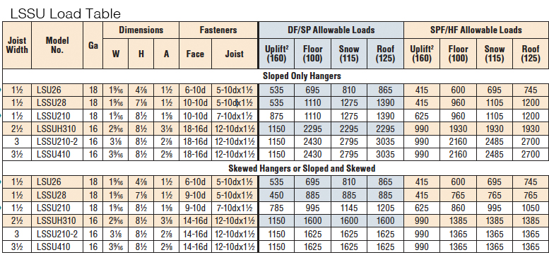
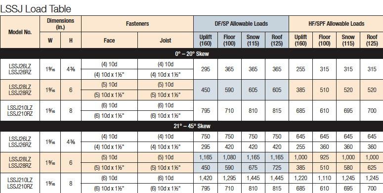
You can see the differences and improvements just by looking at these hangers, installations and load tables. Here’s a different way of showing the advances and benefits of the LSSJ:

LSSJ Improvements
LSSJ Improvements

One of the greatest improvements is the fact that there are fewer nails to install in the LSSJ, and the loads are very similar if not better.

In addition to the LSSJ, Simpson Strong-Tie offers a full line of connectors for wood-framed sloped roofs, including:


We look forward to hearing from you about our newest innovation. For more information about the LSSJ hanger, please see strongtie.com.

Designing Gable End Overhangs

It seems that each major hurricane tends to teach those of us in the construction industry some lesson. With Hurricane Andrew, the lessons were the importance of protection from windborne debris, and the importance of proper construction of gable end overhangs.

There are two main areas where gable ends can fail.

Continue Reading