It seems that each major hurricane tends to teach those of us in the construction industry some lesson. With Hurricane Andrew, the lessons were the importance of protection from windborne debris, and the importance of proper construction of gable end overhangs.
There are two main areas where gable ends can fail.
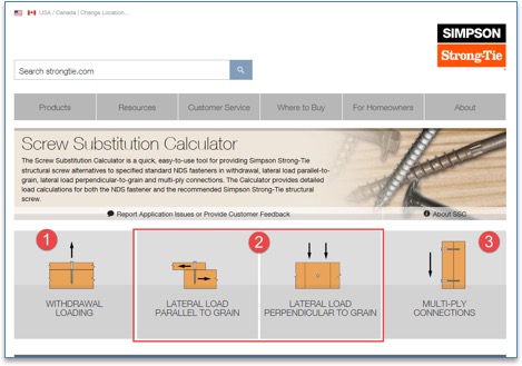
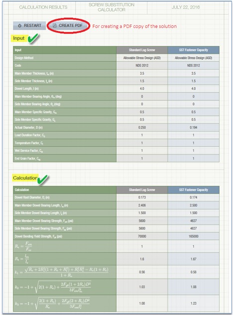
At Simpson Strong-Tie, we do our best to offer tools that make your job easier. One such tool is the Screw Substitution Calculator. It’s a quick and easy-to-use web app created to help you calculate and design using Simpson Strong-Tie fasteners. The app can be used in two ways: (1) to design for a given load and (2) to provide a substitution for NDS fasteners. The app covers design for withdrawal loading, lateral loading and multi-ply connections. For each of these applications you can either design for a load or input the specified NDS fasteners and design an alternate Simpson Strong-Tie screw substitution. The app can generate detailed calculations in a PDF format for any of the selections made, and these calculations can be used for submittals.
Note that although the tool currently does not address corrosion issues, corrosion resistance should be an important consideration before selecting screws for your application.
Below is a screenshot of the Screw Substitution Calculator. As explained above, the app can design for
Withdrawal Loading
Lateral Loading
Multi-Ply Connections
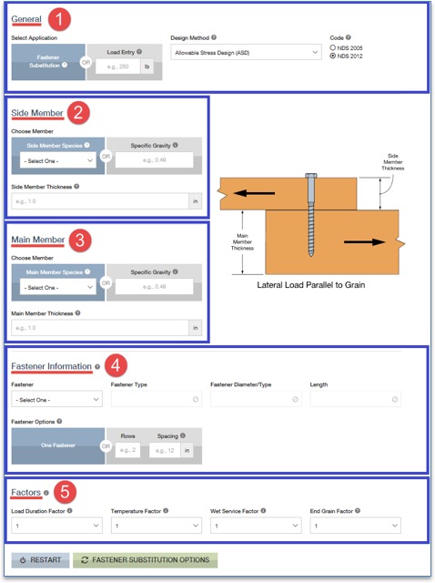
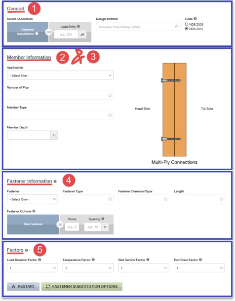
The input sections for Withdrawal Loading and Lateral Loading (parallel or perpendicular to grain) are similar. A screenshot of Lateral Load Parallel to Grain is shown below.
Step 1: General Information– In this section, you are requested to select either Fastener Substitution or a Load Entry. If you choose fastener substitution, the app will request in step 4, Fastener Information, that you enter the original fastener design. The fastener substitution calculator will provide Simpson Strong-Tie fastener alternatives for the NDS fasteners. The NDS fasteners covered in this app are bolts, lag screws, wood screws and nails.
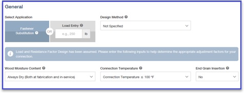
If you choose Load Entry, you will notice that the Fastener Information step will disappear and no longer be available for input. Next, select a category from the Design Method section. Available options are Allowable Stress Design (ASD), Load and Resistance Factor Design (LRFD) and Not Specified, if you are not sure of the design method. If the Not Specified option is selected, the design assumes the Load and Resistance Factor Design method, and it further prompts you to answer a few more questions related to Wood Moisture Content, Connection Temperature and End Grain Insertion.
Step 2: Side Member – In this section, all the information regarding the side member is entered. You can either select a species from the drop-down list or enter the specific gravity of the member manually in the text box. The information button lists all the available specific gravities for wood species combinations from NDS. Then enter the (actual, not nominal) thickness of the side member.
Step 3: Main Member – Similar to step 2, enter all information regarding the main member.
Step 4: Fastener Information – If the Fastener Substitution option is selected in step 1, step 4 will require you to enter information about the NDS fasteners used in the initial design. Enter the fastener type (bolt, lag screw, screw or nail), along with its diameter and length. From the fastener option list you can either select one fastener substitute at a time for each NDS fastener or enter the number of rows and the spacing of NDS-designed fasteners to determine Simpson Strong-Tie fastener options and their spacing requirements.
Step 5: Factors – Enter all factors required for designing the connection. Information pertaining to each factor is provided by clicking the information (i) button. You can use this as a guide for entering the factors.
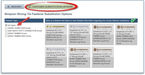
Once all the input is entered, click on the FASTENER SUBSTITUTION OPTIONS button.
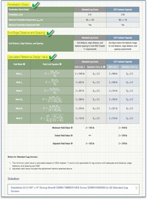
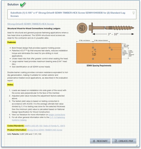
Clicking FASTENER SUBSTITUTION OPTIONS reveals the available solutions. As a default, the All Types box is checked under Fastener Type, as shown above. You can refine the solutions by unchecking this box and selecting any of the specific fasteners listed – SDWH TIMBER-HEX Screw solutions, for example. On the right, the available solutions are displayed for selection. When a selection is made, the app displays all the input and output for that solution as shown in the screenshot below. You can also create a PDF copy for any of the solutions by clicking on CREATE PDF button.
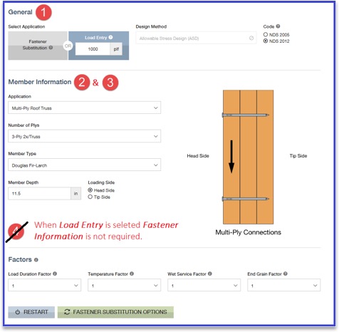
For Multi-Ply Connections, the input for side members and main members is combined into Member Information as shown in the screenshot below. Once the input is entered, click the FASTENER SUBSTITUTION OPTIONS button to display results. Similar to withdrawal loading or lateral loading, you can create a PDF copy of the calculations.
Let’s design a 3-ply connection with (3) 2 x 12 DF members for a load of 1,000 plf.
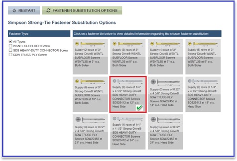
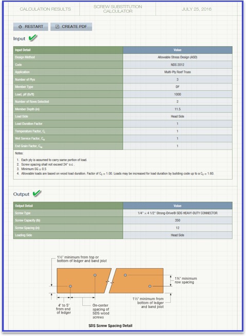
By clicking FASTENER SUBSTITUTION OPTIONS, you can see all the available Simpson Strong-Tie fastener solutions. You can then select any of the options to generate detailed output. A screenshot of the output, solution and information regarding the selected fastener is displayed below. You can create a PDF copy of the solution by clicking the CREATE PDF button.
Now that you know how easy it is to design using our Screw Substitution Calculator, you can start using this tool for your future projects. We welcome your feedback on the features you find useful as well as on how we could make this program better suit your needs. Let us know in the comments below.
When it comes to wood-frame construction, hurricane ties are among the most commonly specified connectors. They play a critical role in a structure’s continuous load path and may be used in a variety of applications, like attaching roof framing members to the supporting wall top plate(s), or tying wall top or bottom plates to the studs. They are most commonly used to resist uplift forces, but depending on regional design and construction practices, hurricane ties may also resist lateral loads that act in- or out-of-plane in relation to the wall.
Simpson Strong-Tie manufactures approximately 20 different models of hurricane ties, not counting twist straps, other clips, or the new fully-threaded SDWC screws often used in the same applications. This assortment of models raises the question, “How do you select the right one?”
In this post, we’ll outline some of the key elements to consider when selecting a hurricane tie for your project.
Demand Load
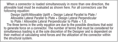
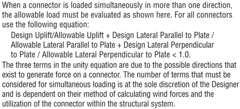
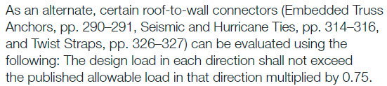
Let’s start with the obvious one. If your building’s roof trusses have an uplift of 600 lb. at each end, don’t select a hurricane tie with a published capacity of less than 600 lb. It’s also important to consider combined loading if you plan to use the tie to resist both uplift and lateral loads. When the connector is resisting lateral loads, its capacity to resist uplift is reduced. I won’t go into too much detail on this topic since it was covered in a recent blog post, but in lieu of the traditional unity equation shown in Figure 1, certain Simpson Strong-Tie connectors (hurricane ties included) are permitted to use the alternative approach outlined in Figure 2.
Figure 1. Traditional Linear Interaction EquationFigure 2. Alternate seismic and hurricane tie applications.
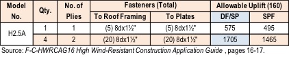
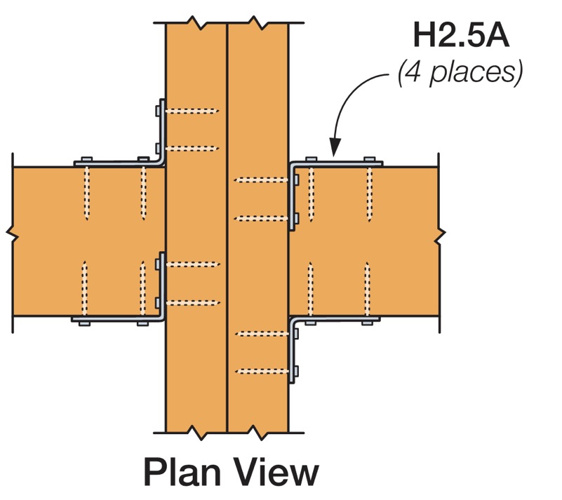
What if the tabulated loads in the catalog for a single connector just aren’t enough? Use multiple connectors! An important note on using multiple connectors, though: Using four hurricane ties doesn’t always mean you’ll get 4x the load. Check out the recently updated F-C-HWRCAG16 High Wind-Resistant Construction Application Guide for allowable loads using multiple connectors and for guidance on the proper placement of connectors so as to avoid potential overlap or fastener interference.
Figure 3. Allowable Load Comparison for Single and Multiple H2.5A ConnectorsFigure 4. Proper Placement of (4) H2.5A’s to Avoid Fastener Interference
Dimensional Requirements
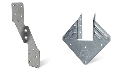
While the majority of the hurricane ties that Simpson Strong-Tie offers are one-sided (such as the H2.5A), some are designed so the truss or rafter fits inside a “U” shape design to allow for fastening from both sides (such as the H1). If using the latter, make sure the width of the truss or rafter is suitable for the width of the opening in the hurricane tie. For example, use our new H1.81Z (not the H1Z) for 1¾” wide engineered roof framing members.
Figure 5. Typical H1.81Z InstallationFigure 6. H2.5A and H1 Hurricane Ties
Additionally, the height of the hurricane tie and the wood members being attached should be compatible. For example, an H2.5A would not be compatible with a roof truss configured with only a nominal 2×4 bottom chord over the plate since the two upper nail holes in the H2.5A will miss the 2×4 bottom chord (see Figure 7). This is actually such a common mis-installation that we specifically tested this scenario and have developed an engineering letter on it (note the greatly reduced capacity). In this case the ideal choice would be the H2.5T, which has been specifically designed for a 2×4 truss bottom chord.
Figure 7. H2.5A Installed on 2×4 Truss Bottom ChordFigure 8. H2.5T Installed on 2×4 Truss Bottom Chord
Fasteners with Hurricane Ties
It’s also essential to pay close attention to the diameter and length of the fasteners specified in the Simpson Strong-Tie literature. While many hurricane ties have been evaluated with 8d x 1½” nails for compatibility with nominal 2x roof framing, some require the use of a longer, 8d common (2½” long) nail and others require a larger-diameter 10d nail.
When specifying products for a continuous load path, it’s a good idea to select connectors that all use the same size nail to avoid improper installations on the job. It’s much easier if the installer doesn’t need to worry about which size nail he currently has loaded in his pneumatic nailer.
Wall Framing
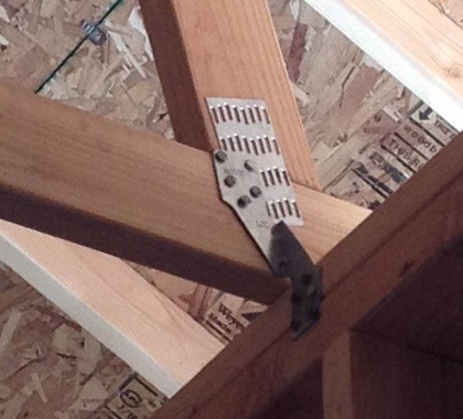
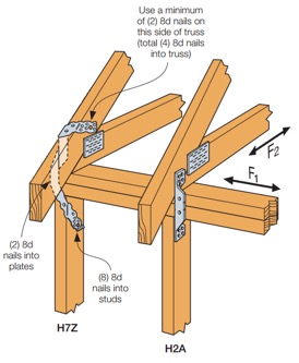
Do your roof and wall framing members line up? If so, creating a continuous load path can be made simpler by using a single hurricane tie to fasten the roof framing to studs. The H2A, H7Z, and H10S are some of the connectors designed to do just that. If your framing doesn’t align, though, you can use two connectors to complete the load path. For simplification and to reduce potential mix-ups in the field, consider selecting the same hurricane tie for your roof framing-to-top-plate and top plate-to-stud connections, like the H2.5A.
Figure 9. Roof-Framing-to-Stud Connection with Single Hurricane Tie
Besides the added benefit of fewer connectors to install, using a single hurricane tie from your roof framing to your wall studs can eliminate top-plate roll, a topic discussed at length in one of our technical bulletins.
Other Factors When Selecting Hurricane Ties
Some additional factors that may influence your selection of a hurricane tie are:
Environmental factors and corrosion should be considered when selecting any product. Nearly every hurricane tie is available in ZMAX®, our heavier zinc galvanized coating, and several are available in Type 316 stainless steel. A full list of products available in ZMAX or stainless steel may be found on our website. On a related note, be sure to use a fastener with a finish similar to that of the hurricane tie in order to avoid galvanic corrosion caused by contact between dissimilar metals.
When retrofitting an existing structure, local jurisdiction requirements will also influence your decision on which hurricane tie to use. As an example, the state of Florida has very specific requirements for roof retrofitting, which we outline in a technical bulletin, and they specifically mention the roof-to-wall connection. Be sure to check with your local city, county or state for specific requirements before you decide to retrofit.
Availability of wind insurance discounts in your area could also affect your decision on which type of hurricane tie to use on your home. Your insurance company may provide a greater discount on your annual premium for ties that wrap over the top of your roof framing and are installed with a certain minimum quantity of nails. Check with your insurance provider for additional information and requirements.
Although this is a lot to take in, hopefully it makes choosing the right hurricane tie easier for you on your next project. Are there any other items you consider in your design that weren’t mentioned above? Let us know in the comments below.
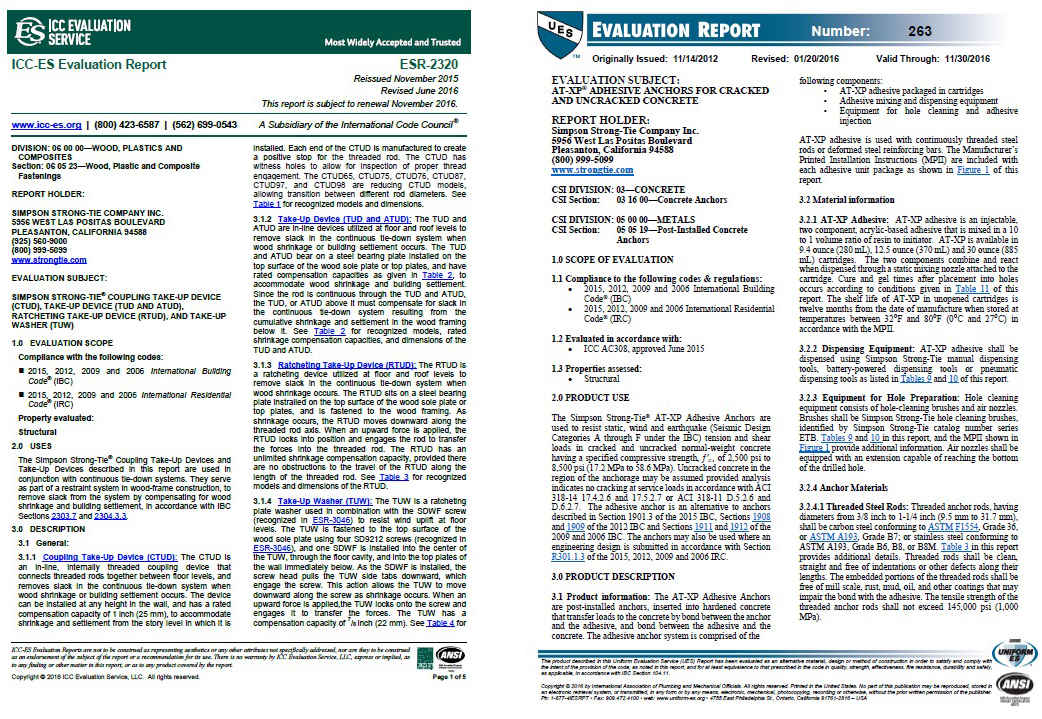
There are products used in every building not referenced by the codes or standards. These products can impact safety, public health and general welfare through their effect on structural strength, stability, fire resistance and other building performance attributes. I-code Section 104.11 (Alternative materials, design, and methods of construction and equipment) provides guidance on how these products are approved for use in the built environment and identifies the Building Official as the decision-maker. This is similar to a referee determining a player’s compliance with the rules.
Building Officials see submittals for a wide variety of alternative building products ranging from the simple to the very complex. The amount of data included in these submittals and their relevance and completeness varies significantly from insufficient and minimal to complete and very thorough. In the absence of publicly developed and majority-approved provisions, the Building Official is tasked to ensure the data provided is appropriate and adequately proves the alternative product meets code intent to protect public safety, no matter the product type or complexity. This is compared to the robust code and standards process in which committees with balanced representation publicly develop and deliberate on provisions in order to protect public safety. The question arises whether the 104.11 requirement implies that a similar robust process be used in the development of test and evaluation requirements for alternative products as is used for the development of code and standard provisions where there is public debate, resolution of negative opinions and a majority approval of the requirements. Requiring a similar code development process for alternative products would seems to make sense. Otherwise, a less rigorous process might be employed by those seeking to avoid a more robust code and standard process so as to achieve quicker and less stringent approval for their alternative products.
Some may argue that having to use a “code-like” evaluation process for alternative products would add too much of a burden in time and cost, and that it’s not necessary since individual registered design professionals and building officials have enough time, resources and expertise to determine acceptability. But this begs the question of why a similar public majority-approval process should not be required for new products as it is required for code-referenced products. Another question that comes up is ongoing acceptance of an alternative product, as their manufacture may have changed since their approval. Additionally, different jurisdictions have different expertise and resources and this can lead to different standards for approval for alternative products, leading to inconsistency.
Is there a solution which balances providing innovative and cost-effective alternative building product solutions to the industry in a timely manner with providing a thorough product assessment using a process similar to the codes and standards to better ensure consistency and public safety? Accredited building product certification companies, or evaluation service companies, that use a publicly developed and majority-approved acceptance or evaluation criteria and publish an evaluation report with the product’s description, design and installation requirements and limitations provide such a solution. These evaluation service companies are a third-party resource for building officials to assist in their determination of whether an alternative product meets code intent and should be approved for use in their jurisdiction.
The number of evaluation service companies has been increasing. The ICC Evaluation Service and the IAPMO Uniform Evaluation Service, two of the better-known such companies, are both ANSI accredited to ISO/IEC 17065 (Conformity Assessment – Requirements for bodies certifying products, processes, and services) to provide building-code product certifications (ICC-ES, IAPMO UES). However, accreditation by itself mainly verifies a certain process is implemented to ensure consistency and confidentiality. Both companies also have a public acceptance or evaluation criteria process. This process includes an evaluation committee made up of building enforcement officials. These officials evaluate the proposed criteria, listen to expert and industry input and only approve the criteria by a majority vote if products evaluated to those criteria will meet code intent. This is similar to how the codes and standards are developed — a transparent public process and a majority approval of requirements and not just an opinion of one or a couple of individuals.
The alternative building product review process for ICC-ES and IAPMO UES is similar and has the following important components.
CRITERIA: The accredited product evaluation service develops an acceptance or evaluation criteria, with the manufacturer’s and public’s input, that is publicly debated, revised and ultimately approved by a majority vote of a committee of building enforcement officials.
TESTING: The manufacturer contracts out to an accredited independent third-party test laboratory to either perform or witness the product testing in accordance with the criteria.
REVIEW: Registered design professionals with the accredited product evaluation service evaluate the testing and analyses performed and sealed by registered design professionals with the manufacturers or their representatives. The product evaluation service then publishes the evaluation report to their website, and the report typically contains the product description, design and installation requirements andlimitations.
CONTINUOUS COMPLIANCE: The manufacturer’s quality system is inspected at least annually by the product evaluation service or an accredited third-party inspection agency to ensure that the product currently being manufactured is the same as that which was evaluated.
While the term “product evaluation” is sometimes used, it is often “product certification” or “product conformity assessment.” ISO/IEC Guide 2:2004 defines “conformity assessment” as “Any activity concerned with determining directly or indirectly that relevant requirements are fulfilled. Some “product certification” companies also provide “product listing” services for when testing and evaluation requirements for the product are already in code-referenced consensus standards, making the development of acceptance criteria unnecessary, thus simplifying the process.
A mechanism is available to the building industry to provide innovative and cost-effective alternative building products in a timely manner that implements a public and majority product acceptance criteria process, similar to the codes and standards development process. This solution involves the Building Official referencing building product evaluation service reports, based on acceptance criteria, offering a robust evaluation better ensuring that an alternative product meets code intent, thus protecting the public. In fact, several jurisdictions do require evaluation service reports for alternative products.
Should there be an easier path to approval for alternative products than for code-referenced products? What is a reasonable path to product approval? What basis do you use in reviewing evaluation or code reports to determine whether an alternative product is “in or out of -bounds”? We’d love to hear your thoughts.
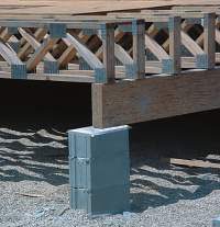
What do a chicken house, a water treatment plant and a raised wood floor system all have in common? Very likely, they all involve preservative-treated lumber. They’re also all examples of common environments in which preservative-treated, metal-plate- connected (MPC) wood trusses may be specified.
Although trusses are successfully used in a variety of environments that require treated lumber, the first mention of “treated lumber” usually sends up a red flag in a truss design office. While the corrosion protection of truss plates is no different from the corrosion protection of any other steel fastener or hanger that comes in contact with treated lumber, there are a few more considerations that come into play whenever treated lumber is going to be used in a truss application.
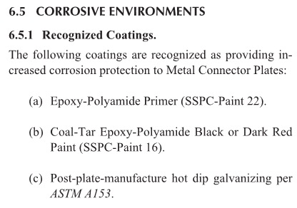
When trusses are used in particularly corrosive environments such as coastal environments or salt storage buildings, the ANSI/TPI 1 standard lists coatings that will provide increased corrosion protection for the plates (see insert, below).
The paint coating systems listed in (a) and (b) have been specified in the TPI standard since 1985. These paint coatings, which are applied to the truss plates after the trusses are manufactured, provide alternatives to the double-dipped galvanized or stainless-steel plates used in coastal high hazard areas. In fact, the ANSI/TPI 1 Commentary states that one study – SSPC Report 87-08, Evaluation of Coatings for Metal Connector Plates – concluded that the paint coating systems over standard galvanized plates would be expected to outperform the double-galvanized metal connector plates in field use.
Coal Tar Epoxy-Coated Metal Connector Plate
Once the necessary corrosion protection of the plates has been addressed, the next consideration is the effect of certain lumber treatments on the truss plates’ lateral resistance, or tooth-holding capacity. Fire-retardant treatments generally require strength reductions to be applied to both the lumber and metal connector plate design values. The proprietary treatment manufacturer specifies these design reductions. As soon as the specific treatment is known, the appropriate design reductions can be easily applied by the truss design software and noted on the truss design drawing accordingly.
Besides lumber treatment, there may be other reasons for plate design reductions whenever extra galvanization or special coatings are required. While extra galvanization itself does not necessarily require a reduction in plate values, if the treated lumber’s moisture content (MC) exceeds 19% at the time of truss fabrication, then a 20% reduction to the tooth-holding values is required. The same 20% reduction applies if the environment for the intended end use of the trusses is expected to result in wood moisture content exceeding 19%.
Special Considerations and Red Flags
One corrosive environment that requires special consideration is an enclosed swimming pool. ANSI/TPI 1 requires that trusses be separated from the pool environment by a vapor barrier and be separately ventilated from the pool environment. The exception to this requirement is if the truss plates are made with a stainless steel that is not susceptible to stress corrosion cracking (SCC), i.e., not Types 304 and 316. Since truss plates made with SCC-resistant stainless steel are not readily available (if at all), a vapor barrier is basically required anytime trusses are used over enclosed swimming pools.
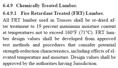
Another important consideration in roof truss applications involving treated lumber is the effect of elevated temperatures. For example, when FRT lumber is going to be used in an environment where high moisture content will exist, an FRT formulated for exterior use may be specified. However, if the exterior FRT has not been tested with elevated temperatures as specified in TPI 1 Section 6.4.9.1, it should not be used in a roof application.
But the biggest concern when treated lumber is specified for use in metal-plate-connected wood trusses has nothing to do with corrosion at all. When a truss Designer gets a job that calls for a preservative treatment for exterior use or an exterior FRT, the very first question will be why is an exterior treatment required/what is the application? Although trusses can be adequately designed for many types of environments, there is one environment that does not mix well with metal-plate- connected wood trusses – exposed exterior applications. The TPI/WTCA Guidelines for Use of Alternative Preservative Treatments with Metal Connector Plates concludes with the following statement:
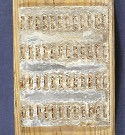
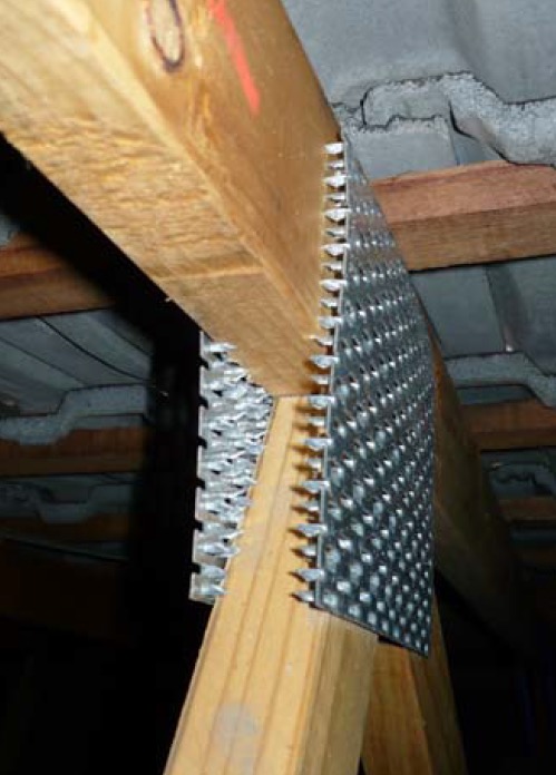
When trusses are exposed to repeated wetting and drying, the corresponding swelling/shrinkage of the wood causes what is commonly referred to as truss plate “back out”. Since the ability of a truss plate to provide lateral resistance depends on the teeth having adequate embedment into the wood members, any plate “back out” or withdrawal from the lumber due to weathering has an adverse effect on the load capacity of the truss plate.
Example of a truss plate that has “backed out”
For this reason, MPC wood trusses must be protected from the elements, from the time they are built and stored through the extent of their life in service. High moisture content that is consistently high can be accounted for; but if the trusses will be exposed to moisture cycling, then it is time to consider something other than a metal-plate-connected wood truss.
What are your experiences with treated lumber and/or corrosive environments and wood trusses? Let us know in the comments section below.
On Thursday, May 5, 2016, Washington State University at Pullman, state dignitaries, construction leaders, WSU construction alumni, PACCAR management, Simpson Strong-Tie management and the press celebrated the grand opening and dedication of the PACCAR Environmental Technology Building (PETB) and the Simpson Strong-Tie Research and Testing Laboratory.
The Simpson Strong-Tie team comprised senior leadership, engineering and marketing representatives, led by our CEO, Karen Colonias. In her speech at the opening ceremony, Karen Colonias highlighted the leadership of Simpson Strong-Tie in the engineering and construction materials industry in the U.S. and the world. She emphasized the longstanding partnership between WSU and Simpson Strong-Tie, which spans over twenty years of collaboration in various testing and code development programs, and communicated our excitement at the opportunity to collaborate more closely with WSU’s highly respected engineering department on testing and engineering programs.
Karen Colonias speaking at the Grand Opening
The Paccar Environmental Technology Building (PETB) is 96,000 square feet and houses the Composite Materials and Engineering Center (CMEC) – a highly integrated hub of interdisciplinary research and education in the areas of renewable materials, sustainable design, water quality, and atmospheric research. The shared space in this new building will foster the synergy needed to find new solutions to complex industry problems, such as creating human environments that are at once safe, economical and resilient.
The Simpson Strong-Tie® Research and Testing Lab at Washington State University (WSU) is a versatile laboratory designed specifically for the structural testing and prototyping of tall timber buildings, post frame buildings, concrete durability, building repair and retrofit and deck safety, as well as seismic and wind mitigation.
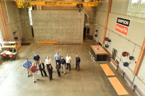
The lab includes a high-capacity reaction 28′ x 46′ concrete floor area with tie-downs, 75-kip capacity at two foot centers through the floor area; a high-capacity wall 28′ long by 2’thick by 18′ tall strong wall that is capable of withstanding a 200-kip reaction in any direction; a central 90-gallon-per-minute hydraulic pump, overhead crate and concrete mixing station. The laboratory is a dynamic space to test new material and design concepts developed in the PETB. This is one of the most visible spaces in the PETB and includes capabilities for mock-ups of new building systems, structural testing and advanced digital manufacturing. Adjoining the lab is an outdoor 32′ by 52′ reaction slab that allows for project display (e.g., Solar Decathlon competition), for developing taller and or larger structures than would be possible on the interior strong floor and for natural weather exposure testing.
The lab is part of the Composite Materials and Engineering Center (CMEC), which has been a leader in the development of wood composite materials for more than 65 years. It is an International Code Council–accredited testing facility. The laboratory highlights engineered wood composites and is constructed of cross-laminated timber, glulam, Parallam and, of course, Simpson Strong-Tie® No- Equal connectors.
Simpson Strong-Tie and WSU, as Karen Colonias mentioned in her speech, have a longstanding and productive partnership going back over 20 years. The two institutions have worked together in a number of areas, including new product testing, deck safety and seismic risk mitigation.
The faculty of the Composite Materials and Engineering Center is committed to addressing the challenge of restoring and improving the U.S. civil infrastructure and offering an integrated approach linking material discovery, manufacturing innovation, product development, and customized design methodologies that will lead to high-performing, cost-effective solutions for the built environment. The core faculty possess diverse expertise that spans materials science (polymers, wood, cement, steel), durability and corrosion protection, manufacturing and sustainable design. The faculty also has a long history of involvement in developing building codes, standards and product acceptance criteria.
This year, the WSU Voiland College of Engineering and Architecture has more than 1,050 students enrolled in civil engineering, architecture and construction management programs. The alumni from these programs are founders of and senior executives in America’s top construction and design firms. The Wall Street Journal ranked WSU among the 25 universities whose graduates are top-rated by industry recruiters, and the Civil Engineering program is the 13th largest in the nation.
On October 29, 2016, and in line with this partnership, Simpson Strong-Tie is conducting its first annual engineering symposium at Washington State University Pullman. In this symposium, Simpson Strong-Tie engineers will share with the engineering and construction management students the various career opportunities that are available in the industry upon their graduation and introduce them to the exciting history of research and innovation at Simpson Strong-Tie. The Symposium will also include testing in the new lab of our No-Equal structural connectors and solutions.
At Simpson Strong-Tie, we are excited to be strengthening the partnership and increasing the collaboration with WSU faculty and students. We are looking forward to an extended and outstanding relationship that drives research and innovations and introduces new methods to design and construct safer, more resilient, sustainable and economical structures.
Larger beams are often built up out of smaller 2x or 1¾” members. This can be done for several different reasons: for the convenience of handling smaller members on the jobsite, or because solid 4x, 6x or glulam material is not readily available, or for reasons of cost. Engineered wood such as laminated veneer lumber (LVL) is often used for its high load capacity and multiple 1¾” plies are built up to get the required capacity for the application.
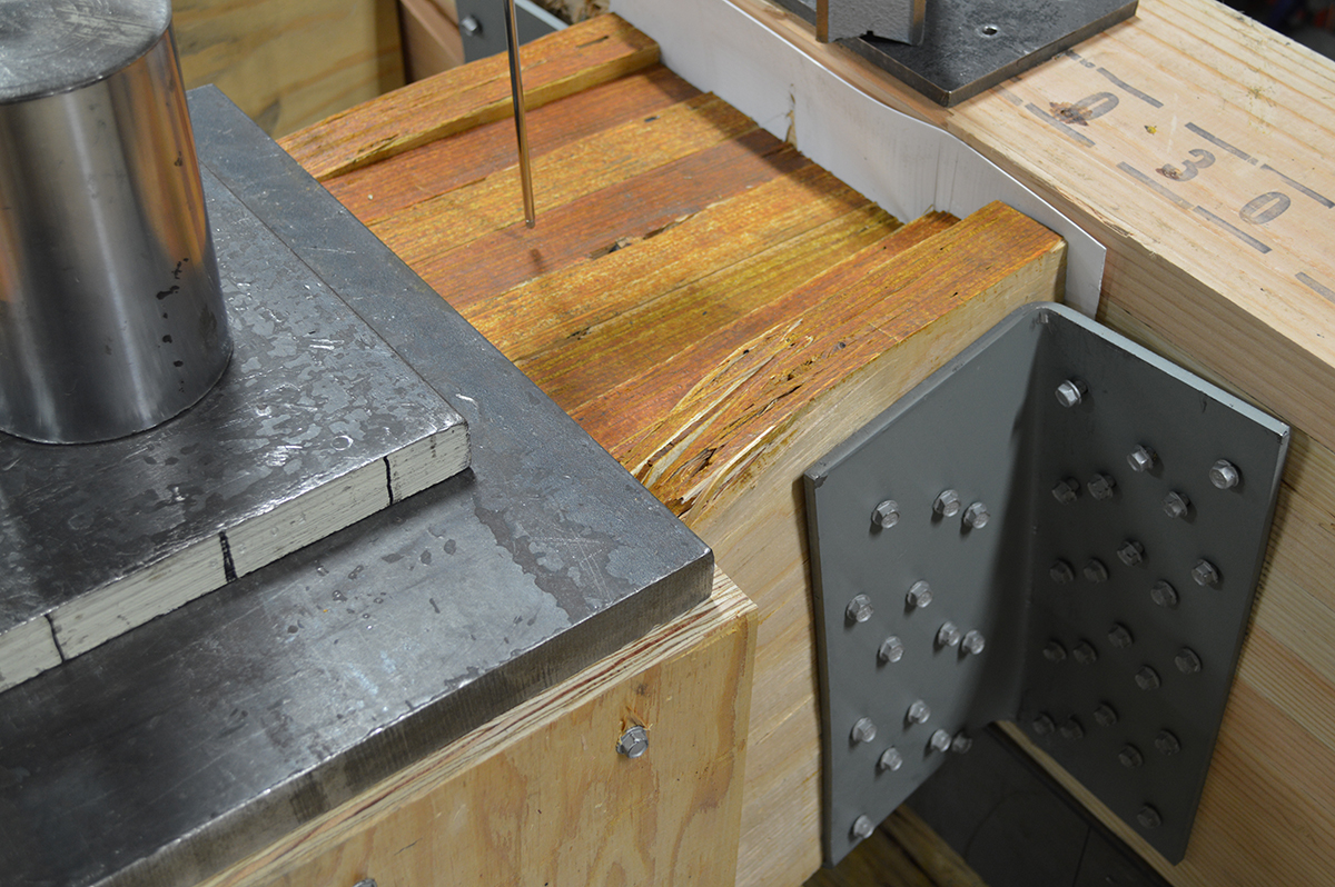
8-Ply LVL Beam in HHGU14 Test
When a built-up beam is loaded concentrically as in the test setup shown, fastening the members is not critical since that giant steel plate will load each ply of the beam. In the field, built-up beams or girders commonly support joists or beams framing into their side. The built-up members must be connected to transfer load from the loaded ply into the other plies.
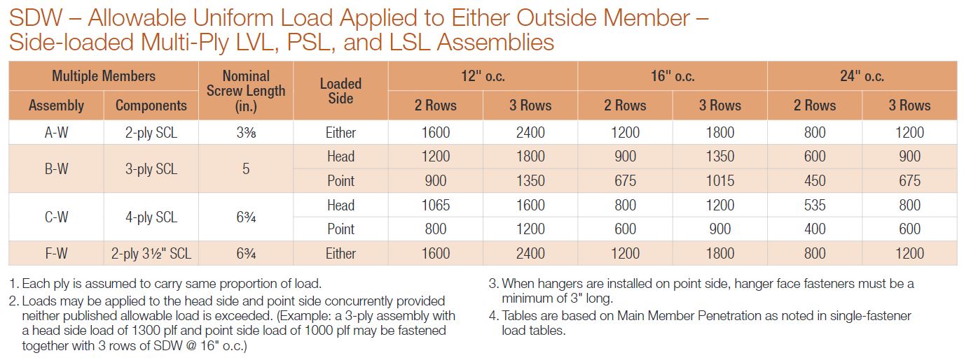
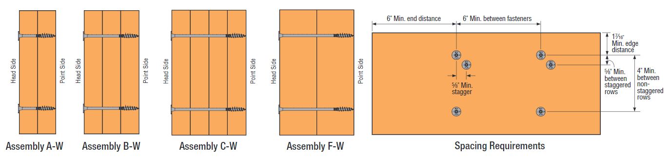
Allowable Uniform Loads and Spacing Requirements
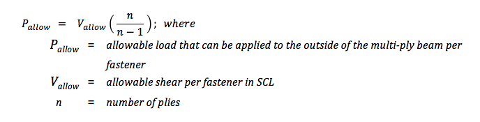
Page 303 of our Fastening Systems catalog, C-F-14 provides allowable uniform load tables for side-loaded multi-ply assemblies using LVL, PSL or LSL material. The calculation for the allowable load applied to the outside ply of a multi-ply beam is:
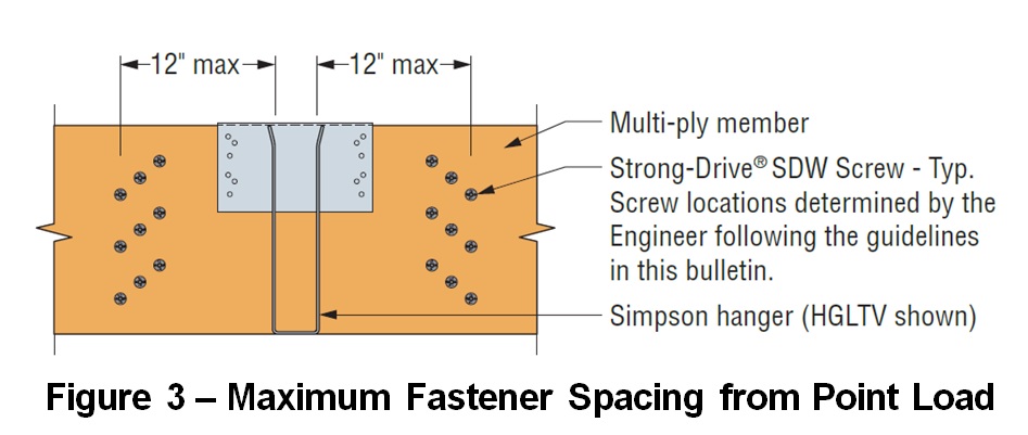
While uniform loads are very common, Designers often request additional information to design multi-ply beam connections to transfer concentrated loads. Simpson Strong-Tie has created a new engineering letter, L-F-SDWMLTPLY16, which complements the information in the Fastening Systems catalog by providing allowable loads in a single fastener format. Designers can use the information to calculate the number of fasteners required for a given point load.
Simpson Strong-Tie® Strong-Drive® SDW EWP-Ply Screw – Allowable Loads for Side-Loaded Multi-Ply Assemblies per Screw
In order to ensure load transfer, the SDW screws need to be located relatively close to the connection. At first glance, it may appear challenging to fit enough fasteners while meeting the non-staggered row-spacing requirements. However, we have found that most loads can be managed by taking advantage of the ⅝” stagger allowance.
SDW – Maximum Fastener Spacing from Point Load
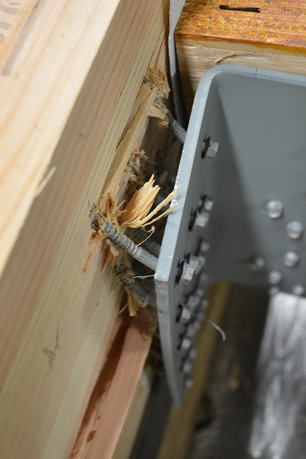
If you are curious what happened in that HHGU14 test, the screws pulled out of the header with a load slightly exceeding 101,000 pounds. Failure photo 2 shows a close-up of the pullout failure. The tested load was very close to the maximum calculated capacity for the SDS screws in the connector, so it was a great test result. What are your thoughts? Let us know in the comments below.
Who likes red rust? No one I know! How do we avoid corroding of fasteners? Corrosion can be controlled or eliminated by providing a corrosion-resistant base metal or a protective finish or coating that is capable of withstanding the exposure environment. When fasteners get corroded, they not only look bad from outside but can also lose their load capacity. To ensure continued fastener performance, we have to control for corrosion. This blog focuses on evaluating the corrosion resistance of the fasteners.
What does the building code specify?
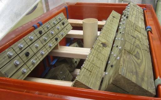
For use in preservative-treated wood, the IBC-2015 specifies fasteners that are hot-dipped galvanized, stainless steel, silicon bronze or copper. Section 2304.10.5.1 of IBC-2015 (Figure 1) covers fastener and connector requirements for preservative-treated wood (chemically treated wood). While chemically treated wood is part of the corrosion hazard, it is not the whole corrosion hazard. Weather exposure, airborne chemicals and other environmental conditions contribute to the corrosion hazard for metal hardware. In addition, the main issue with the code-referenced requirements for fasteners and connectors used with preservative-treated wood is that not all preservative treatments deliver the same corrosion hazard and not all fasteners can be hot-dip galvanized.
Figure 1: Section 2304.10.5.1 IBC-2015.
What if we want to use an alternative base material or coating for fasteners?
How do we evaluate the corrosion resistance of the alternative material or coating? The codes do not provide test methods to evaluate alternate materials and coatings. However, the International Code Council–Evaluation Service (ICC-ES) developed acceptance criteria to evaluate alternative coatings that are not code recognized for use in different environments. The purpose of acceptance criteria ICC-ES AC257, Acceptance Criteria for Corrosion-Resistant Fasteners and Evaluation of Corrosion Effects of Wood Treatment Chemicals, is twofold: (1) to establish requirements for evaluating the corrosion resistance of fasteners that are exposed to wood-treatment chemicals, weather and salt corrosion in coastal areas; and (2) to evaluate the corrosion effects of wood-treatment chemicals. In this blog post, we will concentrate on the evaluation of corrosion resistance of fasteners. The criteria provide a protocol to evaluate the corrosion resistance of fasteners where hot-dip galvanized fasteners serve as a performance benchmark. The fasteners evaluated by these criteria are nails or screws that are exposed directly to wood-treatment chemicals and that may be exposed to one or more corrosion accelerators like high humidity, elevated temperatures, high moisture or salt exposure.
The fasteners may be evaluated for any of the four exposure conditions:
Exposure Condition 1 with high humidity. This test can be used to evaluate fasteners that could be exposed to high humidity. Typical applications that fall under this category are treated wood in dry-use applications.
Exposure Condition 2 with untreated wood and salt water. This test can be used to evaluate fasteners that are above ground but exposed to coastal salt exposure.
Exposure Condition 3 with chemically treated wood and moisture. This test covers all the general construction applications.
Exposure Condition 4 with chemically treated wood and salt water. Typical applications include coastal construction applications.
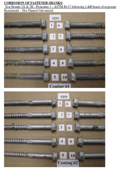
Depending on the exposure condition being used for fastener evaluation, the fasteners are installed in wood that could be either chemically treated or untreated. Then the wood and the fasteners are placed in the chamber and artificially exposed to the evaluation environment. Two types of test procedures are to be completed for exposure condition 2 through 4. The purpose of these tests is not to predict the corrosion resistance of the coatings being evaluated, but to compare them to fasteners with the benchmark coating (ASTM A153, Class D) in side-by-side exposure to the accelerated corrosion environment.
ASTM B117 Continuous Salt-Spray Test
ASTM B117 is a continuous salt-spray test. For Exposure Condition 3, distilled water is used instead of salt water. The fasteners are continuously exposed to either moisture or salt spray in this test, and the test is run for about 1,440 hours after which the fasteners are evaluated for corrosion. This is an accelerated corrosion test that exposes the fasteners to a corrosive attack so the corrosion resistance of the coatings can be compared to a benchmark coating (hot-dip galvanized).
ASTM G85, Annex A5
The second test is ASTM G85, Annex A5 which is a cyclic test with alternate wet and dry cycles. The cycles are 1-hour dry-off and 1-hour fog alternatively. This is a cyclic accelerated corrosion test and relates more closely to real long-term exposure. This test is more representative of the actual environment than the continuous salt-spray test. As in the ASTM B117 test, the fasteners along with the wood are exposed to 1,440 hours, after which the corrosion on the fasteners is evaluated and compared to fasteners with the benchmark coating.
Test Method and Evaluation
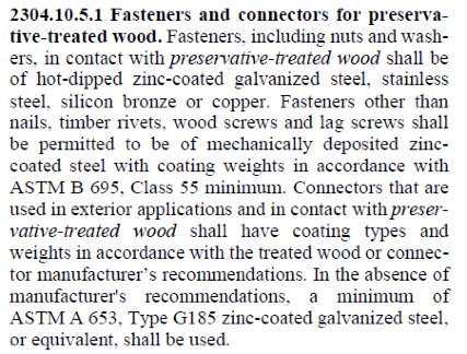
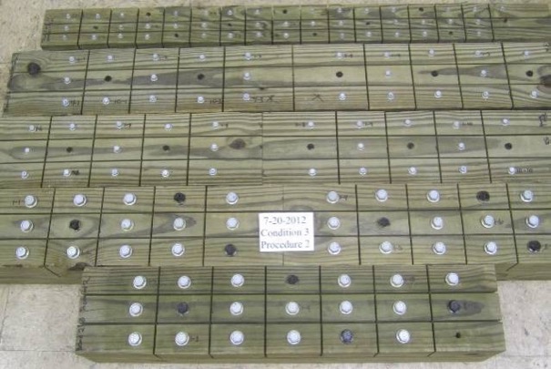
The test process involves installing 10 benchmark fasteners along with 10 fasteners for each alternative coating being evaluated. The fasteners are arranged in the wood with a spacing of 12 times the fastener diameter between the fasteners. A kerf cut is provided in the wood between the fasteners to isolate the fasteners as shown in Figure 2 and to ensure elevated moisture content in the wood surrounding the fastener shank. The moisture and retention levels of the wood are measured, and the fasteners are then installed in the chamber as shown in Figure 3 and exposed to the designated condition. The test is run for the period specified, after which the fasteners are removed, cleaned and compared to the benchmark for corrosion evaluation. Figure 4 shows the wood and fastener heads after 1,440 hours (60 days). The heads and shanks of the fasteners are visually graded for corrosion in accordance with ASTM D610. If the alternate coating performs equivalent to or better than the benchmark coating — that is, if the corrosion is no greater than in the benchmark — then the coating has passed the test and can be used as an alternative to the code-approved coating. Figure 5 shows the benchmark and alternative fasteners that are removed from the chamber after 1,440 hours.
As you can see, the alternative coatings have to go through extended and rigorous testing and evaluation as part of the approval process before being specified for any of the fasteners. Some alternative coatings provide even better corrosion resistance than the code recognized options. Sometimes, also, the thickness of these alternative coatings may be smaller than the thick coating required for hot-dip galvanized parts. Some of our coatings, such as the Double-Barrier coating, the Quik Guard® coating and the ASTM B695 Class 55 Mechanically Galvanized have gone through this rigorous testing and have been approved for use in preservative-treated wood in the AC257 Exposure Conditions 1 and 3. In addition, these coatings have been qualified for use with chemical retentions that are typical of AWPA Use Category 4A – General Ground Contact. No salt is found in AC257 Exposure Conditions 1 and 3. Please refer to our Fastener Systems Catalog, C-F-14, pages 13–15 for corrosion recommendations and pages 16–17 for additional information on coatings.
What do you look for specifically in a fastener? Do you have a preference for a certain coating type or color? Let us know in the comments below!
Figure 2: Fasteners with different coatings along with the benchmark, installed in wood and separated by kerf cuts.Figure 3: Fasteners and wood pieces installed in the chamber.Figure 4: Snap shot of fasteners in ASTM B117 chamber after 1,440 hours.Figure 5: Fasteners after 1,440 hours of exposure, removed from the wood, cleaned and compared to benchmark. Coating 1 – Benchmark (Hot- dip Galvanized) and Coating 2 (Alternative coating).
Did you know that Simpson Strong-Tie is celebrating its 60th birthday this year? We started out with one punch press and the ability to bend light-gauge steel. Then, one Sunday evening in the summer of 1956, Barclay Simpson’s doorbell rang and a request for our first joist hanger led us into the wood connector business. Since then, we’ve continued to grow that business by focusing on our engineering, research and development efforts. Some might say that nowadays we’re an engineering company that also happens to manufacture products, as evidenced by our focus on developing technology tools over the past few years such as web calculators, an updated website and design software. Our focus on technology, however, is really another aspect of our continued commitment to excellence in manufacturing and our application of the tenets of lean manufacturing.
Many of you may already be familiar with the idea of lean manufacturing made famous by Toyota in the early 2000s, along with the principles of continual improvement and respect for people. The concept of continual improvement is based on the idea that you can always make small changes to improve your processes and products. Although they were established in a manufacturing setting, these ideals ring very true for engineering as well; eliminate steps in your design process that don’t add any value to the final project and always be on the lookout for tools or techniques that can speed up your process. Thinking lean isn’t about cutting corners to get your result faster, it’s about mindfully getting rid of the steps that aren’t helping you and finding better ways of doing everyday tasks.
As structural engineers, we can find ourselves working on a variety of projects that lead us to perform repetitive calculations to check different conditions, such as varying parapet heights on the exterior of a building, or we may find ourselves working with an unfamiliar material, such as light-gauge or cold-formed steel (CFS), where we have to take some time away from design to review reference materials such as AISI S200-12 North American Standard for Cold-Formed Steel Framing. Wouldn’t it be great if there were a design tool that could help you complete your light-gauge projects more quickly, in complete compliance with current building codes?
It turns out that Simpson Strong-Tie offers a design tool called CFS Designer™ to help structural engineers improve their project design flow. This program gives engineers the ability to design light-gauge stud and track members with complex beam loading and span conditions according to building code specifications. What does that actually mean, though? Allow me to illustrate with an example of a design project.
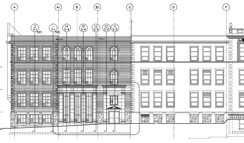
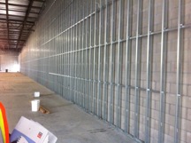
Let’s say you’re designing a building and part of your scope is the exterior wall framing, or “skin” of the building. You probably get sent some architectural plans that look something like this:
Figure 1. Sample building elevation with section marks.
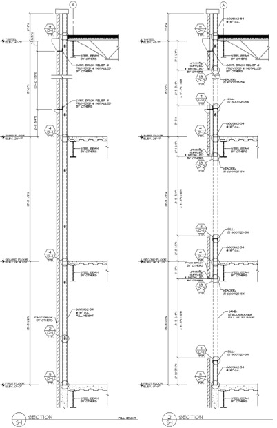
The architectural elevations will have wall section marks indicated for different framing situations. Two sample wall sections are shown in Figure 2.
Figure 2. Sample building wall sections.
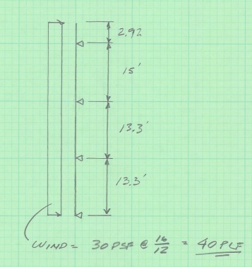
This building has several different wall section types that include door and window locations, varying parapet heights, diverse finish materials that need to meet different deflection criteria, and different connection points back to the base building. The traditional design calculation that you would need to run for one wall section might begin with a loading diagram similar to Figure 3 below.
Figure 3. Sample calculation of wall stud loading diagram.
Once you have your loading diagram generated, you would need to use reference load tables or a computer analysis program to solve for the axial and moment demands, the reactions at the pinned supports, and the member deflections.
After you determine the demand loads, you would then need to select a CFS member with sufficient properties, and you may need to iterate a few times to find a solution that meets the load and deflection parameters. After you’ve selected a member with the right width, gauge and steel strength, you’ll need to select an angle clip that can handle the demand loads, as well as fasteners to connect the clip to the CFS stud and to the base building. You would also need to also check the member design to ensure that it complies with bridging or bracing requirements per AISI. Then, after all that, you’d have to repeat the process again for all of the wall section types for your project.
Figure 4. Hmm, CFS design would sure be a lot easier if buildings were just huge windowless boxes…
Just writing out that whole process took some time, and you can imagine that actually running the calculations takes quite a bit longer. I think we can all agree that the design process we’ve outlined is time-consuming, and here’s where using CFS Designer™ to streamline your design process can really help.
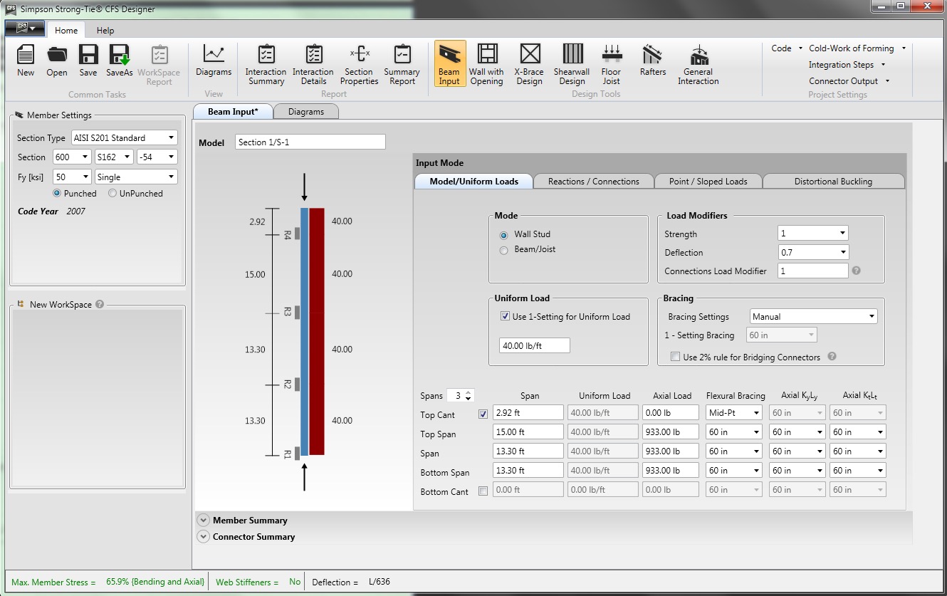
CFS Designer is a structural engineering design program that can automate many of the manual steps that are required in the design process. It has an easy-to-understand graphical user interface that allows you to input your project parameters within a variety of design modules from walls and beams, jambs and headers, X-brace walls, shearwalls, floor joists, and roof rafters. The program also enables the design of single stud or track members, built-up box-sections, back-to-back sections, and nested stud or track sections. Figure 5 shows an example of how you would input the same stud we looked at before into the program.
Figure 5. CFS Designer™ user interface for wall stud design.
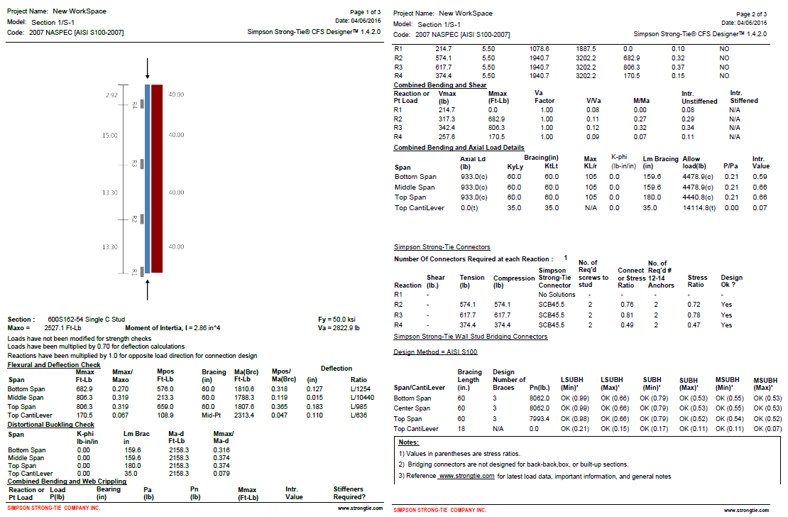
The program will generate the loading diagrams and complete calculation package for all of these different situations. And along with checking the member properties and deflection limits, CFS Designer will also check bridging and bracing requirements and provide connector solutions for the studs using tested and code-listed Simpson Strong-Tie products. Figure 6 shows an example of the summary output you would receive.
Figure 6. The comprehensive summary output page that covers the complete member design down to the bracing and connection solutions.
One unique part of the output is toward the center of the second page, under the heading “Simpson Strong-Tie Connectors.” This section summarizes the tension and compression loads at each reaction point and then shows a connector solution (such as the SCB45.5) along with the number of screws to the stud and the number of #12 sheet-metal screws to anchor back to the base building. Simpson Strong-Tie has developed and tested a full array of connectors specifically for CFS curtain-wall construction as well as for interior tenant improvement framing, which allows designers to select a connection clip straight out of a catalog without needing to calculate their own designs per the code. It’s just another way we’re helping you to get a little leaner!
The last part of the output shown in Figure 6 is titled “Simpson Strong-Tie Wall Stud Bridging Connectors.” It checks the bridging and bracing requirements per AISI S100 and selects a SUBH bridging connector, an innovative bridging solution developed by Simpson Strong-Tie that snaps into place and achieves design loads while only requiring one #10 screw to connect for 75% of applications.
Figure 8. A close-up of the SUBH installed (left) and a wall of studs with bridging installed using the LSUBH clips (right).
You can download a free trial of CFS Designer™ and give it a test drive to see how much time it can save you on a design project. The trial version has almost full functionality, with the exception of not being able to print the output sheets. You can see purchasing information online, and you should always feel free to contact your local Simpson Strong-Tie engineering department with any questions you may have. I hope you are able to take advantage of this great tool to further improve your everyday design processes. We will be sure to keep you updated on our latest technology tools that help speed up the design process. If you’re using CFS Designer, we’d like to hear your thoughts about the program. Please share them in the comments below.
“Structures are connections held together by members” (Hardy Cross)
I heard this quote recently during a presentation at the Midwest Wood Solutions Fair. I had to write it down for future reference because of course, all of us here at Simpson Strong-Tie are pretty passionate about connections. I figured it wouldn’t take too long before I’d find an opportunity to use it. So when I started to write this blog post about the proper selection of a truss-to-wall connection, I knew I had found my opportunity – how fitting this quote is!
There are plenty of photos of damage wrought by past hurricanes to prove that the connection between the roof and the structure is a critical detail. In a previous blog post, I wrote about whose responsibility it is to specify a truss-to-wall connection (hint: it’s not the truss Designer’s). This blog post is going to focus on the proper specification of a truss-to-wall connection, the methods for evaluating those connections under combined loading and a little background on those methods (i.e., the fun stuff for engineers).
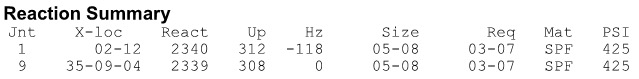
Take a quick look at a truss design drawing, and you will see a reaction summary that specifies the downward reaction, uplift and a horizontal reaction (if applicable) at each bearing location. Some people are tempted to look only at the uplift reaction, go to a catalog or web app, and find the lowest-cost hurricane tie with a capacity that meets or barely exceeds the uplift reaction.
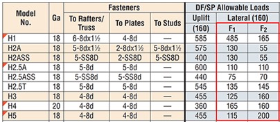
However, if uplift was the only loading that needed to be resisted by a hurricane tie, why would we publish all those F1 and F2 allowable loads in our catalog?
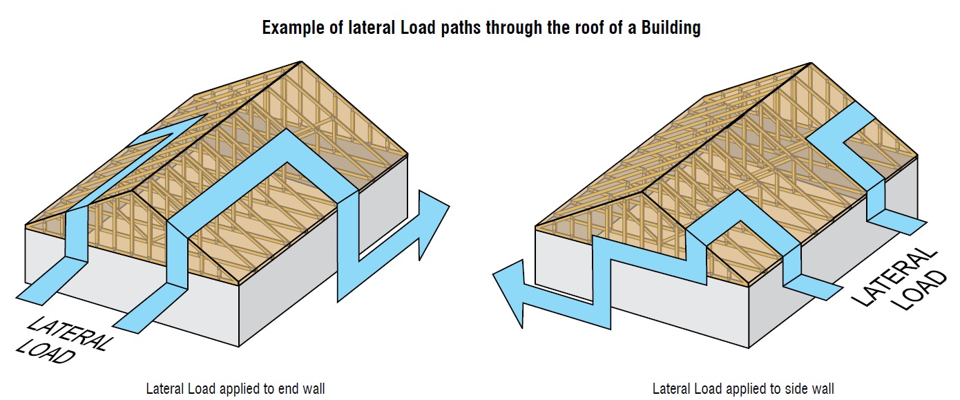
Of course, many of you know that those F1 and F2 allowable loads are used to resist the lateral loads acting on the end and side walls of the building, which are in addition to the uplift forces. Therefore, it is not adequate to select a hurricane tie based on uplift reactions alone.
Excerpt from BCSI (2015 Version)
Where does one get the lateral loads parallel and perpendicular to the plate which must be resisted by the truss-to-wall connection? Definitely not from the truss design drawing! Unless otherwise noted, the horizontal reaction on a truss design should not be confused with a lateral reaction due to the wind acting on the walls – it is simply a horizontal reaction due to the wind load (or a drag load) being applied to the truss profile. It is also important to note that any truss-to-wall connection specified on a truss design drawing was most likely selected based on the uplift reaction alone. There may even be a note that says the connection is for “uplift only” and does not consider lateral loads. In this case, unless additional consideration is made for the lateral loads, the use of that connector alone would be inadequate.
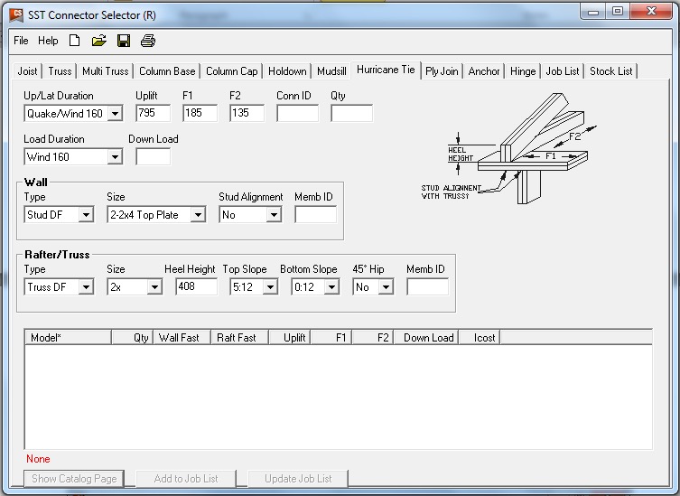
Say, for example, that the uplift and lateral/shear load requirements for a truss-to-wall connection are as follows:
Uplift = 795 lb.
Shear (parallel-to-wall) = 185 lb. (F1)
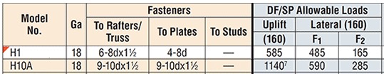
Lateral (perp-to-wall) = 135 lb. (F2) Based on those demand loads, will an H10A work?
An initial look at the H10A’s allowable loads suggests it might be adequate. However, when these loads are entered into the Connector-Selector, no H10A solution is found.
Combined Uplift, F1 and F2 Loads
Why? Because Connector-Selector is evaluating the connector for simultaneous loading in more than one direction using a traditional linear interaction equation approach as specified in our catalog:
If the shear and lateral forces were to be resisted by another means, such that the H10A only had to resist the 795 lb. of uplift, then it would be an adequate connector for the job. For example, the F1 load might be resisted with blocking and RBC clips, and the F2 loads might be resisted with toe-nails that are used to attach the truss to the wall prior to the installation of the H10A connectors. However, if all three loads need to be resisted by the same connector, then the H10A is not adequate according to the linear interaction equation.
Uplift Only
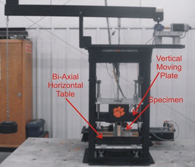
Some might question how valid this method of evaluation is – Is it necessary? Is it adequate? How do we know? And that is where the interesting information comes in. Several years ago, Simpson Strong-Tie partnered with Clemson University on an experimental study with the following primary objectives:
1. To verify the perceived notion that the capacity of the connector is reduced when loaded in more than one direction and that the linear interaction equation is conservative in acknowledging this combined load effect.
2. To propose an alternative, more efficient method if possible.
Three types of metal connectors were selected for this study – the H2.5A, H10, and the META20 strap – based on their different characteristics and ability to represent general classes of connectors. The connectors were subjected to uni-axial, bi-axial and tri-axial loads and the normalized capacities of the connectors were plotted along with different interaction/design surfaces.
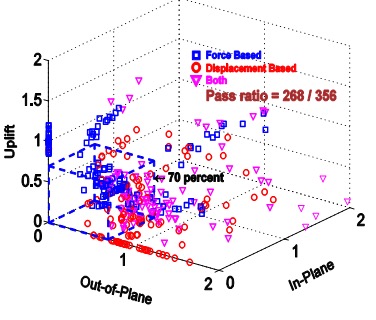
These interaction plots were used to visualize and parameterize the combined load effect on the capacity of the connectors. The three different interaction plots that were examined were the traditional linear relationship, a quadratic interaction surface and a cuboid design space.
Tri-axial Test FrameInteraction plot for tri-axial loads on a cuboid design space
The results? Not only was the use of the linear interaction equation justified by this study, but a new, more efficient cuboid design surface was also identified. It provides twice the usable design space of the surface currently used for tri-axial loading and still provides for a safe design (and for the bi-axial case, it is even more conservative than the linear equation). This alternative method is given in our catalog as follows:
Now we can go back to the H10A and re-evaluate it using this alternative method:
As it turns out, the H10A does have adequate capacity to resist the simultaneous uplift, shear and lateral loads in this example. This just goes to show that the alternative method is definitely worth utilizing, whenever possible, especially when a connector fails the linear equation.
For more information about the study, see Evaluation of Three Typical Roof Framing-to-Top Plate/Concrete Simpson Strong-Tie Metal Connectors under Combined Loading.
What is your preferred method for resisting the combined shear, lateral and uplift forces acting on the truss-to-wall connections? Let us know in the comments below!
We use cookies on this site to enhance your user experience. By clicking "I AGREE" below, you are giving your consent for us to set cookies. Privacy PolicyI AGREE
Privacy & Cookies Policy
Privacy Overview
This website uses cookies to improve your experience while you navigate through the website. Out of these cookies, the cookies that are categorized as necessary are stored on your browser as they are essential for the working of basic functionalities of the website. We also use third-party cookies that help us analyze and understand how you use this website. These cookies will be stored in your browser only with your consent. You also have the option to opt-out of these cookies. But opting out of some of these cookies may have an effect on your browsing experience.
Necessary cookies are absolutely essential for the website to function properly. This category only includes cookies that ensures basic functionalities and security features of the website. These cookies do not store any personal information.
Any cookies that may not be particularly necessary for the website to function and is used specifically to collect user personal data via analytics, ads, other embedded contents are termed as non-necessary cookies. It is mandatory to procure user consent prior to running these cookies on your website.


 There are products used in every building not referenced by the codes or standards.
 limitations.