Deck Fasteners – Deck Board to Framing Attachments

When you’re building a deck, it’s important to know the types of fasteners you need to use with the various materials that are available. On this week’s post we explore some deck fastener applications as well as offer suggestions on how to avoid a few common problems. We will address two generic types of deck boards fastened to wood framing: preservative-treated wood and composite decking.

Preservative-Treated Wood Decking

With preservative treated wood, it pays to know the board treatment. Wood is treated with a water-borne treatment chemical (typically micronized copper azole these days) and then it is either sent out wet or it is kiln dried. Wet-treated wood can have a moisture content (MC) greater than 30%. Wood that is subsequently kiln dried to remove excess moisture after the treatment process is labeled Kiln-Dried After Treatment (KDAT) and has a MC of about 15%. Wood deck boards with preservative treatments will be labeled as such regardless of their moisture condition.

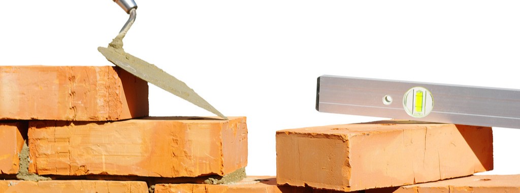
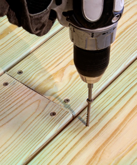
The moisture condition of the deck boards determines how best to fasten and space your deck boards. Wet wood will shrink in width and thickness after installation. As a result, you should install these boards butted tight so that gaps will emerge after they dry in place. On the other hand, KDAT wood or wood that is dry should be installed with 1/8” gaps between boards so there is a slight gap after the boards get wet and swell due to rain, ice and snow. Some manufacturers suggest using an 8d common nail for spacing when installing KDAT decking, as seen in the figure below.

Deck Shrinkage and Swelling

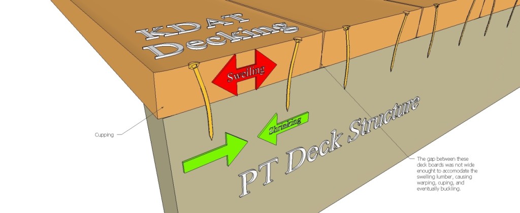
Shrinking and swelling of any installed deck board can cause the deck fastener to bend back and forth with the MC cycling. This causes many deck fasteners to break because of the fatigue loading, which can be exacerbated by the brittle steel used in most deck screws.

To combat this problem, Simpson Strong-Tie developed the DSV Wood screw. This screw is specifically designed with increased ductility to handle the bending induced by deck board movement. It is available in a variety of lengths with threads optimized to prevent jacking between the deck board and the framing, ensuring a snug long-lasting connection.

DSV wood screw
DSV wood screw

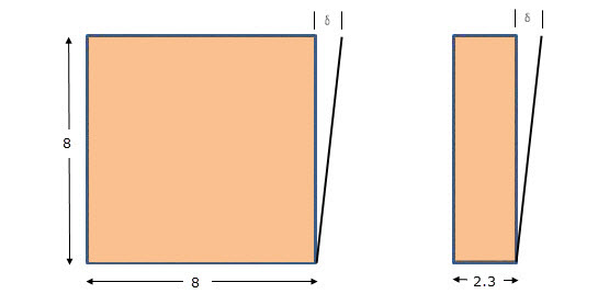
Composite deck boards are made from a mixture of wood fiber and plastic or are entirely “plastic.” Wood plastic composites and plastic materials exhibit thermal expansion, so they expand and contract in thickness, width and length as a function of temperature and solar heating. Consequently, they typically require a special screw designed for composite decking. Screws for this application will often utilize a two-thread design. The lower thread drives the screw into the framing while the upper thread pulls the loosened composite material back into the hole and holds the deck board tight to the joist. Composite screws also have a cap-style head that covers any residual material left around the screw body and leaves a clean finish. Ductility is important to these screws too.

Given the wide variety of composite deck producers, we designed a screw that works well with all of them. The DCU screw works in all types of composite decking fastened to wood framing.

A note about cellular PVC deck boards: the manufacturers’ recommendation of stainless-steel screws restricts the use of many deck board fasteners. Be sure to read and follow the decking material fastener requirements. Simpson Strong-Tie has a broad offering of painted stainless-steel deck screws available to match PVC deck boards. Find the proper match for your board here.

For other deck fastener applications, including decking fastened to steel framing, and information about other deck fasteners available, see our website product page.

Are there other applications that you want to know about that we didn’t share here? Let us know in the comments below. As always, call us in the Engineering Department if you have questions.


Steel Strong-Wall® Footings Just got a Little Slimmer!

While 54 inches is a good height and will get you on most amusement park rides, what about this dimension for the width of a footing? We did some tests recently — actually a lot of tests — that answered that question.

Steel Strong-Wall® narrow panels are great for resisting high seismic or wind loads, but due to their narrow widths, their resulting anchor uplift forces can be rather hefty, requiring very large pad footings. How large? For Seismic Design Categories C-F, the largest cracked concrete solution per ACI318-11 Appendix D has a width of 54 inches and an effective embedment depth of 18 inches in order to ensure the anchor remains ductile. The overall length of this footing, as seen in Figure 1, can be up to 132 inches. While purely code driven, these solutions have historically presented challenges in the field. Most concrete contractors have to dig footings this size by hand. This often leads to discussions with their engineers about finding a better solution.

Figure 1: Slab-on-Grade Installation (Traditional Solution)

Simpson Strong-Tie has been studying cast-in-place anchorage extensively in recent years. Our research has been featured in a couple of blog posts: The Anchorage to Concrete Challenge – How Do You Meet It? and Podium Anchorage – Structure Magazine. Concrete podium slab anchorage was a multi-year test program that started with grant funding from the Structural Engineers Associations of Northern California for initial concept testing at Scientific Construction Laboratories Inc. and wrapped up with full-scale detailed testing completed at the Simpson Strong-Tie Tye Gilb Laboratory in Stockton, California. This joint venture studied the performance of anchorage reinforcement into thin podium deck slabs (10-14 inch) to resist the high overturning forces of continuous rod systems on 4-5-story mid-rise construction. The testing confirmed the need to comply with Appendix D requirements to prevent plastic hinging at anchor locations. Be on the lookout for an SE Blog post on that topic in the near future. Armed with what we learned, we decided to develop tested anchor reinforcing solutions for the Steel Strong-Wall.

The newly developed anchor reinforcement solutions for grade beams are calculated in accordance with ACI318 Appendix D and tested to validate performance. Anchor reinforcement isn’t a new concept, as it’s been in ACI318 for some time. Essentially, anchor reinforcements transfer load from the anchor bolt to the reinforcing, which restrains the breakout cone from occurring. For the new grade beam details, the additional ties near the anchor are designed to resist the load from the anchor and are developed into the grade beam. The new details offer solutions with widths as narrow as 18 inches when anchor reinforcement is used.

Two details have been developed: one for the larger panels (SSW18, SSW21, SSW24) as shown in Detail 1/SSW1.1, and one for the smaller panels (SSW12, SSW15) as shown in Detail 2/SSW1.1. The difference between the two is the number of anchor reinforcement ties specified in Detail 3/SSW1.1. For SSW18, SSW21 and SSW24 panels (Detail 1/SSW1.1), the total number of reinforcement per anchor is specified. Due to their smaller sizes, the anchor reinforcement ties specified in Detail 2/SSW1.1 for the SSW12 and SSW15 panels are the total required per panel.

Detail 1/SSW1.1
Detail 1/SSW1.1
Detail 2/SSW1.1
Detail 2/SSW1.1
Detail 3/SSW1.1
Detail 3/SSW1.1

Validation Testing

From the concrete podium deck anchorage test program, we discovered that the flexural and shear capacity of the slab is critical to anchor performance and must be designed to exceed the demands created by the attached structure. For grade beams, this also holds true. In wind-load applications, this demand includes the factored demand from the Steel Strong-Wall. In seismic applications, our testing and analysis showed that achieving the anchor performance expected by Appendix D design methodologies requires the concrete member design strength to resist the amplified anchor design demand from Appendix D Section D.3.3.4.3.

Validation testing was conducted to evaluate this concept. The test program consisted of a number of specimens with different configurations, including:

  • Closed tie anchor reinforcement
  • Non-closed tie u-stirrup anchor reinforcement
  • Control specimen without anchor reinforcement

Flexural and shear reinforcement were designed to resist Appendix D amplified anchorage forces and were compared to test beams designed for non-amplified strength level forces. The results of the testing are shown in Figure 2. In the higher Seismic Design Categories (C-F), the anchor assembly must be designed to satisfy Section D.3.3.4.3 in ACI318-11 Appendix D. In accordance with D.3.3.4.3 (a), the concrete breakout strength needs to be greater than 1.2 times the nominal steel strength of the anchor, 1.2NSA. This requires a concrete breakout strength of 87 kips for a Steel Strong-Wall that uses a 1-inch high-strength anchor.

Figure 2: Steel Strong-Wall Grade Beam Testing

Grade beams without the anchor reinforcement detail and with flexural and shear reinforcement designed to the Appendix D amplified anchorage forces performed similar to those with closed-tie anchor reinforcement and flexural and shear reinforcements designed to the non-amplified strength level forces. Both, however, came up short of the necessary forces required by Section D.3.3.4.3 (a). From Test V852, we discovered that even though the flexural and shear reinforcement were designed with the amplified forces, the non-closed tie u-stirrups did not ensure the intended performance. From observation, the u-stirrups do not provide adequate confinement of the concrete and tend to open up under loading conditions, resulting in splitting of the beam at the top as can be seen in the photo.

Test V852: Non-Closed U-Stirrups

Tests W785 and W841 resulted in the best performance. Both test specimens contained flexural and shear reinforcement designed for the amplified forces, as well as closed-ties. Two configurations were tested to study their performance — two piece closed-tie anchor reinforcement in W785 and a single piece closed-tie anchor reinforcement in Test W841. As seen in Figure 2, their performance was very similar, and met the requirements of Section D.3.3.4.3 (a). The closed-ties helped confine the concrete near the top of the beam, allowing the assembly to reach the expected performance load (See the photo below). It’s important to indicate the following specifics in the New Grade Beam Anchor Reinforcement Details:

  • Anchor Reinforcement is #4 closed-ties
  • SSWAB embedment depth is 16″ +/- ½” (as shown in Detail 3/SSW1.1). This is to ensure there is enough development length of the anchor reinforcement on both sides of the theoretical breakout surface as required by ACI318-11 D.5.2.9.
  • The minimum distances from the anchor bolt plate washer to top and bottom of closed tie reinforcement are 13 inches and 5 inches respectively to ensure proper development above and below the concrete breakout cone (refer to Detail 3/SSW1.1).
  • The spacing between the two vertical legs of the anchor reinforcement tie must be 10 inches apart. While this may differ from your shear reinforcement elsewhere in the grade beam, it ensures the reinforcement is located close enough to the anchor and adequate development length is provided.
  • Flexural reinforcement (top and bottom) and shear reinforcement (ties throughout the grade beam length) are per the designer. Simpson Strong-Tie has provided information in Detail 3/SSW1.1 for the applicable minimum LRFD Applied Design Seismic Moment (See Figure 3) to make sure the grade beam design will at least resist the applied anchor forces. Project design loads not related to the Strong-Wall panel also should be considered and could control the grade beam design.
Closed-Tie Anchor Reinforcement
Figure 3: LRFD Applied Design Seismic Moment

Simpson Strong-Tie is interested in hearing your thoughts on the new details. What is your opinion? How have the new details been received on your job sites?

Testing Fasteners for Deck Ledger Connections

This week’s blog post was written by Aram Khachadourian, R&D Engineer for Fastening Systems. Since joining Simpson Strong-Tie 14 years ago, he has designed and tested holdowns, hangers, truss connectors and anchor bolts. He has drafted numerous acceptance criteria as well as quality standards. His current focus is the development, testing and code approval of structural fasteners. Prior to his work at Simpson Strong-Tie, he spent his time designing steel buildings including strip malls, wineries and airplane hangars. Aram graduated from the University of California at Davis with a Civil Engineering degree, and is a registered professional engineer in California.

As we approach the beginning of spring, homeowners across the country are starting to turn their thoughts to the backyard and making plans to add a new deck for summer enjoyment.

As a contractor, designer, or homeowner, you want to know that this new deck will have the structural integrity to stand firm for many years and remain safe for everybody who will use it. While there are many aspects to building a safe, strong deck, today we are focusing on the attachment of the deck ledger to the structure.

Prior to 2009, numerous catastrophic deck failures attributed to improper deck ledger attachments demonstrated the need for building code guidance. A calculated solution was overly conservative because the sheathing layer, typically present between the deck ledger and the structure’s band joist, was considered to be a gap in the connection. A prescriptive approach to deck ledger attachments was finally introduced in the 2009 International Residential Code (IRC). Table R502.2.2.1 provided fastener spacings for ½”-diameter lag screws and bolts. These values were based on testing conducted by researchers at Virginia Tech and Washington State University.

The tests included a variety of band joist types, with pressure-treated Hem-Fir as the deck ledger material. The deck ledger was tested at high moisture content to represent a wet, worst-case field condition. The test assembly had a load bar spanning two joists that were attached to the deck ledger with joist hangers. The ledger was attached through the sheathing to the rim board. Only the rim board was supported by the test frame. The average ultimate load was divided by a factor-of-safety of 3 and then further divided by the load duration coefficient of 1.6 to achieve an allowable load. These values were then applied to a deck live load of 40 psf plus a deck dead load of 10 psf to derive allowable fastener on-center spacings for various joist spans.

When Simpson Strong-Tie began to rate fasteners for ledger connections, we used a similar method of testing and analysis. However, we incorporated a few changes. One of the changes we implemented was a symmetric test set-up.  The original test assembly had a ledger on one end of the joists and a support member as the boundary condition on the other. We put a ledger at each end of the joists so stiffness differences in the supports would not affect the test results. We also chose a larger factor-of-safety of 3.2 (instead of 3.0) to maintain consistency with calculation of fastener allowable loads in other applications. In order to provide our customers with a broader range of construction options, we tested many typical rim board and ledger materials, and we ran tests with single and double ledgers. You can see an example of a typical test set up here:

A typical testing set up
Testing deck ledger connections.

We have tested many Simpson Strong-Tie® Strong-Drive® fasteners for ledger applications including the SDWS Timber screw (SDWS22DB), SDWH Timber-Hex SS screw (SDWH-SS), SDWH Timber-Hex screw (SDWH19DB), and SDS Heavy-Duty Connector screw (SDS). We also have information regarding ledgers attached to studs and ledgers fastened over gypsum board. You can find all of this information in our latest fastener catalog.

One final construction tip – deck ledgers can fail due to cross-grain tension. This occurs when the joist hangers are attached to the deck ledger near the bottom of the ledger, but the fasteners holding the ledger to the building are near the top of the ledger. To prevent cross-grain tension failure, place the joist hangers so at least half of the ledger fasteners are below the joist hanger line.

Take a look through the various ledger options in our fastener catalog, and if we don’t address your condition, let us know. As always, call us in the Engineering Department if you have questions.

Please share your feedback in the comments area below.

New Treatment of Shear Wall Aspect Ratios in the 2015 SDPWS

This post was co-written by Simpson Engineer Randy Shackelford and AWC Engineer Phil Line.

The 2015 International Building Code references a newly updated 2015 Edition of the American Wood Council Special Design Provisions for Wind and Seismic standard (SDPWS). The updated SDPWS contains new provisions for design of high aspect ratio shear walls. For wood structural panels shear walls, the term high aspect ratio is considered to apply to walls with an aspect ratio greater than 2:1.

Figure 1. SDPWS 2008 Table 4.3.4 and illustration of shear wall with height, h and length, bs

In the 2015 SDPWS, reduction factors for high aspect ratio shear walls are no longer contained in the footnotes to Table 4.3.4 (See Figure 2). Instead, these factors are included in new provisions accounting for the reduced strength and stiffness of high aspect ratio shear walls.

Figure 2. SDPWS 2015 Table 4.3.4

Deflection Compatibility – Calculation Method

New Section 4.3.3.4.1 states that “Shear distribution to individual shear walls in a shear wall line shall provide the same calculated deflection, δsw, in each shear wall.” Using this equal deflection calculation method for distribution of shear, the unit shear assigned to each shear wall within a shear wall line varies based on its stiffness relative to that of the other shear walls in the shear wall line. Thus, a shear wall having relatively low stiffness, as is the case of a high aspect ratio shear wall within a shear wall line containing a longer shear wall, is assigned a reduced unit shear (see Figure 3).

Figure 3. Illustration of deflection compatibility


In addition, Section 4.3.4.2 contains a new aspect ratio factor, 1.25 – 0.125h/bs, that specifically accounts for the reduced unit shear capacity of high aspect ratio shear walls. The strength reduction varies linearly from 1.00 for a 2:1 aspect ratio shear wall to 0.81 for a 3.5:1 aspect ratio shear wall. Notably, this strength reduction applies for shear walls resisting either seismic forces or wind forces. For both wind and seismic, the controlling unit shear capacity is the smaller of the values from strength criteria of 4.3.4.2 or deflection compatibility criteria or 4.3.3.4.1.

Deflection Compatibility – 2bs/h Adjustment Factor Method

The 2bs/h factor, previously addressed by footnote 1 of Table 4.3.4, is now an alternative to the equal deflection calculation method of 4.3.3.4.1 and applies to shear walls resisting either wind or seismic forces. This adjustment factor method allows the designer to distribute shear in proportion to shear wall strength provided that shear walls with high aspect ratio have strength adjusted by the 2bs/h factor. The strength reduction varies linearly from 1.00 for 2:1 aspect ratio shear walls to 0.57 for 3.5:1 aspect ratio shear walls. This adjustment factor method provides roughly similar designs to the equal deflection calculation method for a shear wall line comprised of a 1:1 aspect ratio wall segment in combination with a high aspect ratio shear wall segment.

In prior editions of SDPWS, a common misunderstanding was that the 2bs/h factor represented an actual reduction in unit shear capacity for high aspect ratio shear walls as opposed to a reduction factor to account for stiffness compatibility. The actual reduction in unit shear capacity of high aspect ratio shear walls is represented by the factor, 1.25 – 0.125h/bs, as noted previously. The 2bs/h factor is the more severe of the two factors and is not applied simultaneously with the 1.25-0.125h/bs factor.

What are the major implications for design?

  • For seismic design, the 2bs/h factor method continues unchanged, but is presented as an alternative to the equal deflection method in 4.3.3.4.1 for providing deflection compatibility. The equal deflection calculation method can produce both more and less efficient designs that may result from the 2bs/h factor method depending on the relative stiffness of shear walls in the wall line. For example, design unit shear for shear wall lines comprised entirely of 3.5:1 aspect ratio shear walls can be as much as 40% greater (i.e. 0.81/0.57=1.42) than prior editions if not limited by seismic drift criteria.
  • For wind design, high aspect ratio shear wall factors apply for the first time. For shear walls with 3.5:1 aspect ratio, unit shear capacity is reduced to not more than 81% of that used in prior editions. The actual reduction will vary by actual method used to account for deflection compatibility.
  • The equal deflection calculation method is sensitive to many factors in the shear wall deflection calculation including hold-down slip, sheathing type and nailing, and framing moisture content. The familiar 2bs/h factor method for deflection compatibility is less sensitive to factors that affect shear wall deflection calculations and in many cases will produce more efficient designs.

As the 2015 International Building Code is adopted in various jurisdictions, designers will need to be aware of these new requirements for design of high aspect ratio shear walls. The 2015 SDPWS also contains other important revisions that designers should pay attention to. The American Wood Council provides a read-only version of the standard on their website that is available free of charge.

Please contribute your thoughts to these new requirements in the comments below.

What Factors Contribute To A “Resilient” Community?

The world has seen many increasingly catastrophic natural disasters in the past decade, including Hurricane Katrina (Category 3) striking New Orleans in 2005, 2010’s 7.0 magnitude Haiti and 8.8 magnitude Chili earthquakes, the 9.0 magnitude Japan earthquake along with the Christchurch earthquake (6.3 magnitude) in 2011, the tornado outbreak in 2011 which included an EF4 striking Tuscaloosa, AL and a multiple-vortex EF5 striking Joplin, MO. We also saw Category 2 Hurricane Sandy, the largest Atlantic hurricane on record in 2012 and the EF5 tornado striking Moore, Oklahoma in 2013.

Continue Reading

Anchor Testing for Light-Frame Construction

I started off doing a four-part series on how connectors, fasteners, concrete anchors and cold-formed steel products are tested and load rated. I realized that holdown testing and evaluation is quite a bit different than wood connector testing, so there was an additional post on holdowns. We have done several posts on concrete anchor testing (here and here), but I realize I never did a proper post about how we test and load rate concrete products per ICC-ES AC398 and AC399.

AC398 – Cast-in-place Cold-formed Steel Connectors in Concrete for Light-frame Construction and AC399 – Cast-in-place Proprietary Bolts in concrete for Light-frame Construction are two acceptance criteria related to cast-in-place concrete products.

Cold-formed steel connectors embedded in concrete are not considered in ACI 318 Appendix D, so it was necessary to create criteria for evaluating those types of connectors. Some examples of products covered by AC398 are the MASA mudsill anchor, CBSQ post base, and the STHD holdown.

MASA mudsill anchor
MASA mudsill anchor
CBSQ post base
CBSQ post base
STHD holdown
STHD holdown

ACI 318 Appendix D addresses the design of cast-in-place anchors. However, the design methodology is limited to several standard bolt types.

ACI 318 Appendix D Cast-in anchors

There are a number of anchor bolt products that have proprietary features that fall outside the scope of ACI 318, so AC399 fills in that gap by establishing test procedures to evaluate cast-in-place specialty anchors. Simpson Strong-Tie SB and SSTB anchor bolts are two families of anchors we have tested in accordance with AC399.

SB Anchor Bolt
SB Anchor Bolt
SSTB Anchor Bolt
SSTB Anchor Bolt

SB and SSTB anchors have a sweep geometry which increases the concrete cover at the anchored end of the bolt, allowing them to achieve higher loads with a 1¾” edge distance. The SSTB is anchored with a double bend, whereas the SB utilizes a plate washer and double nut.

AC398 (concrete connectors) and AC399 (proprietary bolts) are similar in their test and evaluation methodology. AC398 addressing both tension and shear loads, whereas AC399 is limited to tension loads. Testing requires a minimum of 5 test specimens. These are the allowable load equations for AC398 and AC399:

AC398 - Allowable Load Equation
AC398 – Allowable Load Equation
AC399 - Allowable Load Equation
AC399 – Allowable Load Equation

For comparison, here is the standard AC13 allowable load equation for joist hangers:

Allowable Load = Lowest Ultimate / 3

Without getting into Greek letter overload, what are these terms doing?

Nu (or Vu) is the average maximum tested load. Calculating averages is something I actually remember from statistics class. Everything else I have to look up when we do these calculations.

(1 – K x COV) uses K as a statistical one-sided tolerance factor used to establish the 5 percent fractile value with 90% confidence. This term is to ensure that 95% of the actual tested strengths will exceed the 5% fractile value with 90% confidence. COV is the coefficient of variation, which is a measure of how variable your test results are. For the same average ultimate load, a higher COV will result in a lower allowable load.

The K value is 3.4 for the minimum required 5 tests, and it reduces as you run more tests. As K decreases, the allowable load increases. In practice, we usually run 7 to 10 tests for each installation we are evaluating.

Table A2.1 – K values for evaluating the characteristic capacity at 90% confidence

Rd is seismic reduction factor, 1.0 for seismic design category A or B, and 0.75 for all others. This is similar to what you would do in an Appendix D anchor calculation, where anchor capacities in higher seismic regions are reduced by 0.75.

Rs and Rc are reduction factors to account for the tested steel or concrete strength being higher than specified. There are some differences in how the two acceptance criteria apply these factors, which aren’t critical to this discussion. Φ is a strength reduction factor, which varies by failure mode and construction details. Brittle steel failure, ductile steel failure, concrete failure and the presence of supplemental reinforcement.

The α factor is used to convert LRFD values to ASD values. So α = 1.0 for LRFD and α = 1.4 for seismic and 1.6 for wind. Both criteria also allow you to calculate alpha based on a weighted average of your controlling load combinations. This has never made a lot of sense to me in practice. If you are going to work through the LRFD equations to get a different alpha value, you might as well do LRFD design.

MASA - Test Setup MASA - Test Failure

Rse is a reduction factor for cyclic loading, which is applied to proprietary anchor bolts covered under AC399, such as the SSTB or SB anchors. A comparison of static load and cyclic load is required for qualification in Seismic Design Category C through F. Unlike the cracked reduction factor, manufacturers cannot take a default reduction if they want recognition for high seismic.

Due to the differences in AC398 and AC399 products, the load tables are a little different. AC398 products end up with 4 different loads – wind cracked, wind uncracked, seismic cracked and seismic uncracked.

CBSQ Load Table
CBSQ Load Table

AC399 products are a little simpler, having just wind and seismic values to deal with.

SSTB Load Table
SSTB Load Table

What are your thoughts? Let us know in the comments below.

Resilience by Design: City of Los Angeles Lays Out a Seismic Safety Plan

“From a seismological standpoint, Northridge was not a big earthquake.” This is first sentence of the “Resilience by Design” report by L.A. Mayor’s Seismic Safety Task Force led by Dr. Lucy Jones of the U.S. Geological Survey (USGS). The report is the culmination of a year-long investigation into the greatest vulnerabilities of the city from a major seismological event. Continue Reading

Don’t Get Washed Away – The Next Wave of Pile Fastener Innovation Has Arrived

For decades, bolts were used for pile construction to ensure a structurally sound connection. While this works on paper, these types of bolted connections are not user friendly to install in the field. The more difficult the connection is to make, the more likely it won’t be done right.

Many pile connections have stringers or beams on each side of the pile. This means the predrilled hole for the bolt must be properly aligned through all of the parts. It takes considerable strength and the skill and care of a craftsman to do this properly, often from the top of a ladder. Given the large size of many piles, the installer also has to tighten the bolt while blind to the back of the assembly. It can take a few minutes per fastener to get the job done right. These conditions have created a great need in the field for a better approach.

Pile connection

After much design and testing, Simpson Strong-Tie has come out with a new faster and safer solution, the SDWH Timber-Hex HDG screw. The screw has a special point, so no predrilling is required. The installation of this fastener takes a matter of seconds, not minutes. This adds up to hours of saved labor costs.

SDWH Timber-Hex HDG screw

More information about the SDWH Timber-Hex HDG screw can be found in the newly released flier F-F-SDWHHDG14, which is on our website.

Loads for these screws are presented two ways. First, there are individual fastener connection values based on screw length and wood side-plate thickness. Second, loads are given for entire assembly connections. These loads are based on the testing of specific fastener layouts. Our assembly testing used piles with one or two stringers attached to each side of the pile. Here is an example of a load table for stringer-to-square pile connection loads.

Connection Loads

Connection assembly layouts are shown in the F-F-SDWHHDG14 flier for square piles, round piles, piles with continuous stringers and piles with stringers that are spliced at the pile. Here is one example below:

SE Blog 4

We are testing additional assemblies as other connections, materials and conditions are identified.

If you have a common condition that you don’t see addressed in the flier, please let us know in the comments below. You can also always call us in the Engineering Department if you have questions.

The New Truss Design Standard: Enter to Win A Copy of ANSI/TPI 1-2014 National Design Standard for Metal Plate Connected Wood Truss Construction

If you are like me, then you enjoy this time of the year. Instead of looking back and reviewing the events of the past year, this is the month for looking ahead at the year to come and what’s in store. So what is in store for 2015?

For the truss industry, there is a new truss design standard that was just released the last week of December. Still hot off the press, the ANSI/TPI 1-2014 standard is a revision to the 2007 edition and is referenced in the 2015 International Building Codes.

While the 2015 I-Codes might take some time for some municipalities to adopt, others are gearing up for adoption of the 2015 I-Codes as early as mid-2015. Either way, it is always good to know what is in the latest and greatest code-referenced design standards. So here’s a look at the new ANSI/TPI 1-2014 truss design standard:

The New ANSI/TPI 1-2014 Standard

First, here is a brief primer on the TPI 1 standard. The Truss Plate Institute (TPI) published the first truss design criteria in 1960. Many updates to these design criteria followed after that, and in 1995, TPI published its first ANSI-accredited truss design standard, ANSI/TPI 1-1995. Subsequent editions of this American National Standard have included ANSI/TPI 1-2002, ANSI/TPI 1-2007, and now ANSI/TPI 1-2014. All of the TPI standards, including archived copies going all the way back to TPI-60, are available from TPI (www.tpinst.org). Here is a link to the overview of non-editorial changes from ANSI/TPI 1-2007 to ANSI-TPI 1-2014.

While the 2007 edition included many significant revisions to the previous edition, the 2014 standard has relatively few substantive changes to the 2007 edition, which is good news for those who are still trying to catch up. Chapter 2 covers the design responsibilities involved in metal plate connected wood truss construction and looks different at first glance because it has been reorganized. However, the actual “Design Responsibilities” as they were defined in TPI 1-2007 have not changed.

In short, two separate sections in TPI 1-2007, which address design responsibilities in projects that require registered design professionals and projects that do not, have now been combined into one section. The “Truss Design Engineer” is simply referred to as the “Truss Designer” and the “Registered Design Professional for the Building” is simply the “Building Designer.” If the project requires registered design professionals, then the Truss Designer and Building Designer will be registered design professionals. Regardless of whether or not those two parties are registered design professionals, their responsibilities relating to the design and application of metal plate connected wood trusses are the same, so defining those responsibilities once within the TPI standard simplifies things and makes more sense.

Not new to the wood industry, but new to TPI 1-2014, are provisions for Load and Resistance Factor Design (LRFD). AF&PA incorporated LRFD provisions into the 2005 National Design Specification (NDS) for Wood Construction, and the TPI standard has followed suit, using the same basic approach as the NDS.

The section in TPI 1-2014 with the most changes is the section on deflection criteria. The deflection criteria have been revised in the last three editions of the TPI standard. Starting in TPI 1-2002, a requirement was added to consider creep in total deflection calculations. However, specific creep factors were not specified in the standard and were only presented in the Commentary. In the 2007 edition, creep factors were moved into the standard, and the total deflection calculation explicitly specified a component due to creep of no less than 50 or 100 percent of the initial deflection for long-term loads for dry and green (wet service) use, respectively. This was consistent with the 1.5 and 2.0 creep factors specified in the NDS for total deflection calculations for seasoned and unseasoned conditions.

Between the 2007 and 2014 editions, an inconsistency was discovered between the TPI 1 deflection criteria and the deflection limits in the U.S. model building codes. While the intent of the TPI standard was to present the same basic L/xxx deflection limits for Live Load and Total Load as the model building codes, it was discovered that the IBC deflection limits for “DL + LL” were actually intended to address only the creep portion of the dead load deflection plus the immediate live load deflection. So although long-term deflection including proper creep considerations can be an important consideration in the overall design of the building, it is not intended to be used to limit the design of a truss with respect to building-code established limits on vertical deflection.

Excerpt from the ANSI/TPI 1-2014 Commentary

To resolve the issue of inconsistent methods used in the building industry to specify deflection limits, the 2014 edition now distinguishes between the following:

• “Deflection due to Live Load Plus Creep Component of Deflection due to Dead Load” for purposes of meeting the IBC deflection limits for DD + LL, which is defined as

ΔCR = Δ LL + (Kcr ‐1) x Δ DL

• “Long-Term Deflection”, which includes the full effect of creep but for which there are no explicit deflection limits specified in TPI

• “Deflection due to Total Load”, which is based on the full load (including both dead load and live load), but includes no explicit creep factors. The deflection due to total load has the same deflection limits as the IBC deflection limits for DD + LL, but this is not a mandatory check in TPI; it only applies to trusses if the Building Designer specifies that such a check due to total load be performed. Further, any consideration for creep in that calculation would also have to be specified by the Building Designer.

In recognition of the increased creep in trusses compared to solid sawn beams, the creep factors have been increased to 2.0 and 3.0 for dry and green (wet service) use, respectively. For purposes of deflection checks in accordance with the IBC, these factors reduce to 1.0 and 2.0, respectively, since the equation for “Deflection due to Live Load Plus Creep Component of Deflection due to Dead Load” uses KCR-1 rather than KCR as the factor on the immediate deflection due to dead load.

What does this all mean? For the majority of truss applications (e.g., dry-service), the effect of switching from TPI 1-2007 to TPI 1-2014 will be a change in creep factor from 1.5 to 1.0, unless additional requirements are specified by the Building Designer. Those additional requirements may include a limit on long-term deflection or a check for total load deflection (subject to the TPI deflection limits), including any considerations for creep.

A complete listing of the changes in TPI 1-2014 and more discussion about these changes are available in the TPI 1-2014 Commentary.

Now is your chance to win a copy of the ANSI/TPI 1-2014 standard for your own design library! Simply post a truss-related question, comment or idea for a future truss-related blog topic, and we will enter you into a drawing during the week of Jan 15-22. One winner will be picked at random. We look forward to hearing from you!

Here Come 2015 IBC Changes!

All of us here at Simpson Strong-Tie hope you had a happy and successful 2014. It seems that the folks at the International Code Council had a good year. True to their plan, the 2015 editions of the International Codes were published during the summer so that they are ready for adoption in 2015.

SE blog 1

SE blog 2Simpson Strong-Tie was tracking a number of issues during the development of the 2015 International Building Code and International Residential Code. Here is a summary of some of the significant changes that users will see in the 2015 International Building Code (IBC).

One significant change affecting Simpson Strong-Tie was the removal of the requirements for evaluation of joist hangers and similar devices from Chapter 17, and the revision of Sections 2303.5 and 2304.10.3 to reference ASTM D 7147 as the test standard for joist hangers.

Since the primary reference standard for design in Chapter 16, ASCE 7-10 has not changed; there were not a lot of significant changes in that chapter. The definitions of “Diaphragm, rigid” and “Diaphragm, flexible” were deleted from Chapter 2, and a sentence was added to 1604.4 stating when a diaphragm can be considered rigid, along with a reference to ASCE 7 for determining when designs must account for increased forces from torsion due to eccentricity in the lateral force resisting system.

In Chapter 19, significant improvements were made to the sections that modify ACI 318 so that the IBC and the standard are coordinated, correcting the problems in the 2012 IBC.  In addition, Sections 1908 (ASD design of anchorage to concrete) and 1909 (strength design of anchorage to concrete) were deleted to remove any conflict with ACI 318 anchor design methods.

In Chapter 23, a new section was added to address cross-laminated timber, requiring that they be manufactured and identified as required in APA PRG 320. The wood framing fastening schedule was completely reorganized to make it easier to use and the requirements for protection of wood from decay and termites were rewritten. Section 2308 on Conventional Light-Frame Construction was completely reorganized with significant revisions to the wall bracing section. As discussed in an earlier blog post, the holdown requirement for the portal frame with holdowns (now called PFH bracing method in the 2015 IBC) has been reduced from a required capacity of 4,200 pounds to 3,500 pounds.

Se blog 3

For designers, some of the most significant changes are in Chapter 35, which lists referenced standards. Some major standards that were updated for this edition of the IBC include ACI318-14, ACI530/530.1-13, several AISI standards (S100-12, S200-12, S214-12, and S220-11), several new and revised ASCE standards (8-14, 24-13, 29-14, 49-07, and 55-10), almost all the AWC standards (WFCM-2015, NDS-2015, STJR-2015, PWF-2015 and SDPWS-2015), AWS D1.4/D1.4M-2011, most NFPA standards (too many to list), PTI DC-10.5-12, SBCA FS 100-12 and TPI 1-14.

Kudos to the American Wood Council. They have posted view-only versions of all their referenced standards online, so designers do not have to buy new editions every time the code changes. AISI also enables one to download PDFs of the framing standards at www.aisistandards.org.

Finally, a couple of ICC Standards were updated to new versions that are referenced in the IBC: ICC-500-14, ICC/NSSA Standard on the Design and Construction of Storm Shelters; and ICC 600-14, Standard for Residential Construction in High-Wind Regions.

A future blog post will cover significant changes in the 2015 IRC. Please share your comments below.