


As soon as news spread that 7.8-magnitude and 7.3-magnitude earthquakes struck Nepal in April and May of this year, earthquake structural engineering experts from our firm, Miyamoto International, hopped on planes from three countries to offer assistance. We do this in hopes that our expertise and technical advice might help stricken communities recover; help them to build better and ultimately help save lives.Continue Reading

Florida Product Approvals Made Simple

This year, the new 5th Edition of the Florida Building Code was released and is now in effect statewide. First printed in 2002, the Florida Building Code was developed as part of Florida’s response to the destruction caused by Hurricane Andrew and other hurricanes in the state.
Another component, which I would like to take a closer look at in today’s post, is a separate Florida Product Approval system designed to be a single source for approval of construction products for manufacturers, Designers and code enforcers. This single system streamlines the previous approach of different procedures for product approval in different jurisdictions. While statewide approval is not required, many jurisdictions, manufacturers and specifiers prefer using the statewide system to the alternative, which is called local product approval. To ensure uniformity of the state system, Florida law compels local jurisdictions to accept state-approved products without requiring further testing and evaluation of other evidence, as long as the product is being used consistent with the conditions of its approval.
The rules of the Florida Product Approval system are in Florida Rule 61G20-3. Here is some basic information about Florida Product Approval.
The Florida Product Approval system is only available for “approval of products and systems, which comprise the building envelope and structural frame, for compliance with the structural requirements of the Florida Building Code.” So users will only find certain types of products approved there. However, if you work in areas where design for wind resistance is required, the Florida system can be a gold mine of information for tested, rated and evaluated products. Not only will you find products like Simpson Strong-Tie connectors with our ICC-ES and IAPMO UES evaluation reports, but thousands of other tested and rated windows, doors, shutters, roof covering materials and other products that don’t typically get evaluation reports from national entities. The specific categories of products covered under the Florida system are exterior doors, impact protective systems, panel walls, roofing, shutters, skylights, structural components and windows.
To protect consumers, a recent law passed in Florida states that a product may not be advertised, sold or marketed as offering protection from hurricanes, windstorms or wind-borne debris unless it has either State Product Approval or local product approval. Selling unapproved products in this way is considered a violation of the Florida Deceptive and Unfair Trade Practices Act.
Once a manufacturer understands the process for achieving a statewide approval, it is not difficult to achieve, but it can be expensive. The manufacturer must apply on the State of Florida Building Code Information System (BCIS) website at www.floridabuilding.org. To prove compliance with the code, the manufacturer must upload either a test report, a product certification from an approved certification entity, an evaluation report from a Florida Professional Engineer or Architect, or an evaluation report from an approved evaluation entity (ICC-ES, IAPMU UES, or Miami-Dade County Product Control). Then, the manufacturer must hire an independent validator to review the application to ensure it complies with the Product Approval Rule and that there are no clerical errors. Finally, once the validation is complete, staff from the Department of Business and Professional Regulation reviews the application. Depending on the method used to indicate code compliance, the application may be approved at that time or it may have to go through additional review by the Florida Building Commission.
Here are several ways to find out if a product is approved.
- For Simpson Strong-Tie products, we maintain a page on www.strongtie.com that lists our Florida Product Approvals.
- The Florida Department of Business and Professional Regulation maintains a page where users can search Product Approvals by categories such as manufacturer, category of product, product name, or other attributes such as impact resistance or design pressure.
- A third-party group we work with has created a website called www.ApprovalZoom.com that lists various product evaluations and product approvals. In addition to listing Florida Product Approvals, they also list ICC-ES evaluation reports, Miami-Dade County Notices of Acceptance, Texas Department of Insurance Approvals, Los Angeles Department of Building Safety Approvals, AAMA certifications and Keystone certifications among others.

The process for searching for approved products on the Florida BCIS is fairly simple.
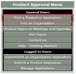
- Go to www.floridabuilding.org
- On the menu on the left side of the page, click on Product Approval. Or, click this link to go directly to the search page.
- On the Product Approval Menu, click on Find a Product or Application. Note that at this location you can also search for approved organizations such as certification agencies, evaluation entities, quality assurance entities, testing laboratories and validation entities.
- Ensure the proper Code Version is shown. The current 2014 Florida Code is based on the 2012 International Codes.
- At this point, several options can be searched. You can search for all approvals by a specific product manufacturer or a certain type of building component by searching Category and Subcategory, or if searching for a specific product, by entering the manufacturer’s name and the product name.
I hope you find the information contained in the Florida Product Approval system useful. Do you have other needs to find approved products?

Kids + Structural Engineering = The Tech Challenge!
This week’s post comes from Marlou Rodriguez who is an R&D Engineer at our home office. Prior to joining Simpson Strong-Tie, Marlou worked as a consulting engineer. His experience includes commercial, multi-family residential, curtain wall systems and the design of seismic bracing for non-structural components. Marlou is a licensed professional Civil and Structural Engineer in California, and too many other states to list. He received his bachelor’s degree in Architectural Engineering from Cal Poly San Luis Obispo. Here is Marlou’s post.Continue Reading

Truss Repair Information: The Never-Ending Search
Truss repair is one of the most frequently asked about truss topics. Not surprisingly, when we asked for suggested truss topics in a truss blog earlier this year, truss repair information made the list. Because the summer months bring about a peak in new construction – and plenty of truss repairs to go along with it – the beginning of June is the perfect time to visit this topic.
From trusses that get dropped or cut/drilled/notched at the jobsite, to homeowners who want to modify their existing trusses to add a skylight or create attic space to fire-damaged trusses, a multitude of scenarios fall under the broad topic of truss repair. Today’s post focuses on various references and resources that can provide some assistance. But first it helps to break down the broad “truss repair” topic into more manageable-sized categories.
New Construction vs. Recent Construction vs. Old Construction
By far, the easiest type of truss repair is new construction, when the trusses either haven’t been installed yet or are still in the process of being installed. Whether the repair is relatively simple (e.g. a broken web) or a little more complicated (e.g. the trusses need to be stubbed), the beauty of new truss construction is that the truss manufacturer – and truss Designer – can be contacted and help with the repair. The truss Designer can easily open up the truss designs in the truss design software, quickly evaluate the trusses for the appropriate field conditions and issue a repair.
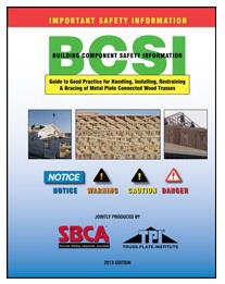
A good reference related to truss repairs for new truss construction is the Building Component Safety Information (BCSI) booklet jointly produced by SBCA and TPI. Section B5 of the BCSI booklet, which is also available as a stand-alone summary sheet, covers Truss Damage, Jobsite Modifications & Installation Errors. This field-guide document describes the steps to take when a truss at the jobsite is damaged, altered or improperly installed, common repair techniques, and the information to provide to the truss manufacturer when a truss is damaged, which will assist in the repair process.
The next easiest truss type to repair is recent construction, where the trusses were constructed recently enough that: a) the truss plates are easy to identify, and b) the truss design drawings may even still be available. In these cases, design professionals other than the original truss Designer may be contacted to repair the trusses. For some types of repairs, the design professional can work off the truss design drawing to design the repair. Other times it might be necessary to model and analyze the truss using structural design software; alternatively, a truss manufacturer can be contacted to model the truss in their truss design software for a fee.
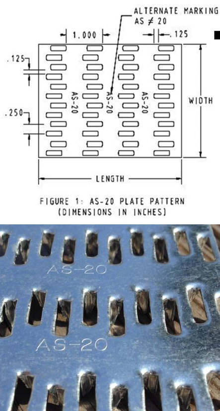
Often, the design professional wants to know the design values for the truss plates that were used to construct the truss. If there are truss design drawings available, they will indicate which truss plates were used in the design, and then the truss plate manufacturer can be contacted for more information. It is also easy to search for the truss plate code reports online (for instance, check icc-es.org). If no truss design drawing is available, there is still a way to identify the truss plates. Currently, there are only five major truss plate manufacturers in the United States, and they are listed on the Truss Plate Institute website. That makes identification of the truss plates used in recently constructed trusses easier because all of the current manufacturers’ plates will have markings that are described in their code reports. (Note that there are also a couple of truss manufacturers in the U.S. that manufacture their own truss plates.)
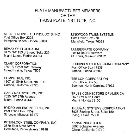
Finally, the most challenging type of trusses for truss repairs are those found in older buildings. Design professionals involved in these types of repair often aren’t sure where to start. Truss design drawings are often not available, and the act of trying to identify the truss plate manufacturer is challenging at best, unsuccessful at worst. As a point of reference, there were 14 truss plate manufacturers that were TPI members in 1987 (see image below), and only one of those companies is still in the current list of five companies. Therefore, the truss plates found in a truss built around 1987 will be difficult to identify. One option is to contact TPI and see if they can point you in the right direction.
Simple vs. Complex Repairs
Another way to break down truss repairs is to divide them into easy and challenging repairs. People often ask for “standard” truss repair details. Unfortunately, standard details only address the simplest types of repair; and those usually aren’t the types of repair that are asked about. Details simply cannot cover the wide range of truss configurations and every type of repair situation.
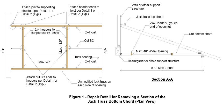
With the exception of simple repairs, most truss repairs rely heavily on the judgment and experience of the design professional doing the repair. And because there are not entire textbooks devoted to truss repair (that I am aware of, anyway), Designers must pull from a variety of resources, both to learn more about truss repair and to design the repair. For repairs using plywood or OSB gussets, the APA Panel Design Specification is a must-have reference. Some people prefer to use dimension lumber scabs for their repairs, whenever possible, simply because they are more familiar with dimension lumber (and the NDS) than they are with Plywood/OSB or the APA Panel Design Specification.
Next, the fasteners for the repair must be selected and the allowable loads determined. For nail design values, I am a big fan of the American Wood Council’s Connection Calculator, which provides allowable nail shear values for just about any combination of main and side members that you can think of, including OSB and plywood side members – particularly handy for truss repairs. For more complex repairs, and especially repairs involving higher forces, an excellent fastener choice is a structural wood screw such as our Strong-Drive® SDS or SDW screws. When I worked in the R&D department at Simpson Strong-Tie, a frequently asked question was whether we had double-shear values for our SDS screws. The questions always seemed to come from Designers who wanted them for truss repairs. Fortunately, we do have double-shear values for our SDS screws. You can find them on page 136 of our Fastening Systems Technical Guide.
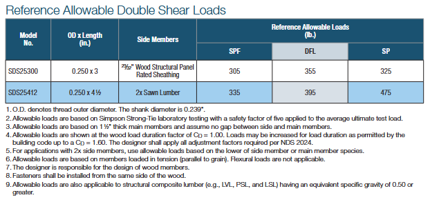
The Strong-Drive SDW screw was developed after the SDS screw, and while there are currently no double-shear values for the SDW, it is still another good option for repairs.
Fire-Damaged Trusses and Truss Collapses
These situations are in a category by themselves because they go beyond even the most complex repairs involving a major modification to the truss. The biggest difference is that the latter case involves mostly known facts and perhaps some conservative assumptions, whereas damage due to fire or collapse includes many unknowns. Most of the truss Designers I have spoken to about truss damage due to fire or truss collapse often recommend replacement of the trusses rather than repair because it is usually too difficult to quantify the damage to the lumber and/or joints. In fires, there can be “hidden” damage due to the sustained high temperatures, while the truss appears to have no visible damage. Likewise, in a truss collapse, not only may there be too many breaks in the trusses involved in the collapse, but there may also be trusses that suffered severe stresses during the collapse and have damage that is not visible. To attempt a repair in either of these cases often requires an inspection at the jobsite, and the result may still end up being replacement of some or all of the trusses. Therefore, the cost of a full-blown inspection should be weighed against the cost of replacing the trusses.
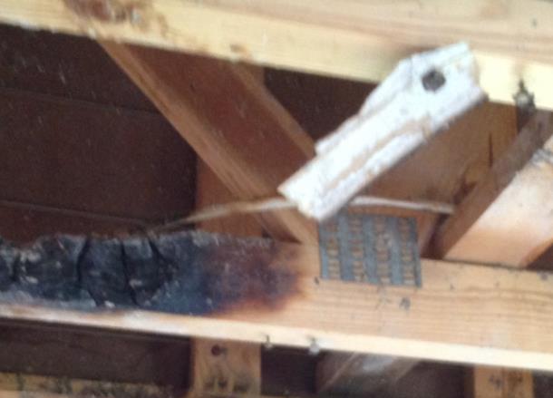
The Structural Building Components Association website has a page with information pertaining to fire issues. It includes a couple of documents related to fire damage that are worth checking out.
Beyond the Blog: Where to Get More Truss Repair Information
The best bet for getting practical design information related to truss repairs is to keep an eye out for short courses, workshops or seminars. ASCE has hosted a Truss Repair Seminar (Evaluating Damage and Repairing Metal Plate Connected Wood Trusses) in the past and may very well offer something like it again. Virginia Tech recently hosted a short course on Advanced Design Topics in Wood Construction Engineering, which included a section on Wood Truss Repair Design Techniques.
What other references or resources for truss repair do you use? Are there any upcoming truss repair courses that you know of? Please let us know in the comments below!
Anchor Reinforcement for Concrete Podium Slabs
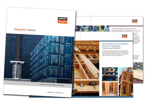
How often do you get the opportunity to high five a co-worker in the office? Maybe it’s when you just worked through a complex calculation, or finally figured out that tough detail. Whatever it might be, there are times when we should raise a hand and celebrate the hard work that we do. So when we recently relaunched the Simpson Strong-Tie Strong-Rod™ Systems website, which includes a link to our new Shallow Podium Anchorage Solutions, there were a few high fives going around the office. With that in mind, we want to share the latest developments and continue our anchorage-to-concrete blog discussions that began in May 2012, continued with a March 2014 post referencing the Structure magazine article on anchor testing, and more recently one discussing our release of anchor reinforcement solutions for Steel Strong-Wall® shearwall to grade beams.

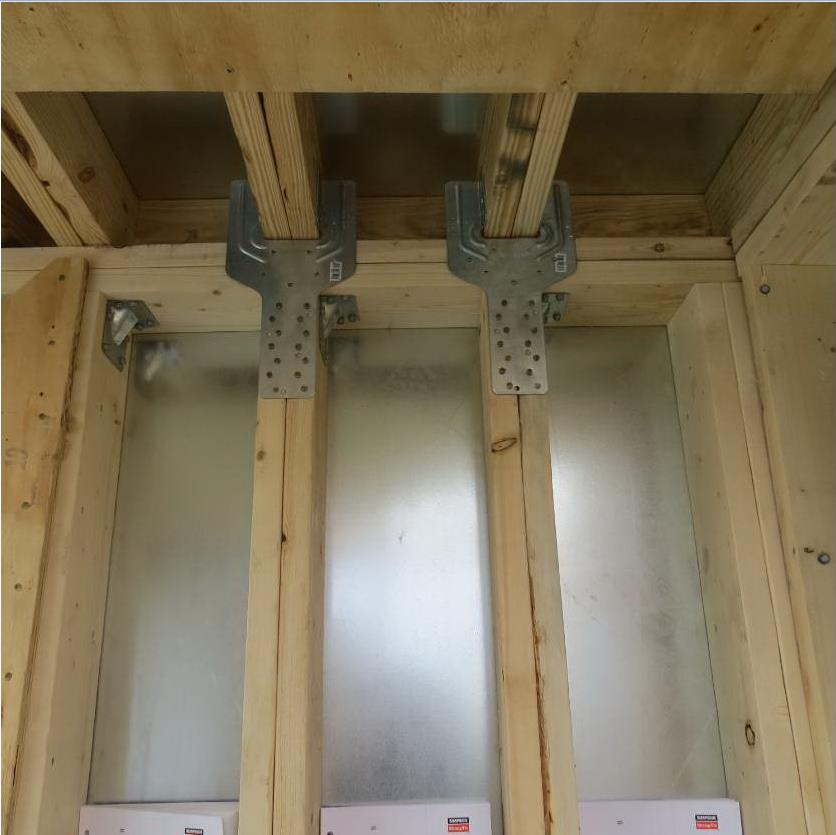
Continuous Rod Restraint Systems for Multi-Story Wood Structures
This week was our new employee Sales and Product Orientation class. Although breaking stuff is fun, my second favorite part of the class is teaching about the importance of a continuous load path. I think it is really the most important thing a Structural Engineer does. If we don’t pay attention to the loads, where they occur and create a path so they can get where they need to go, a building may not stand up. This week, we also released some new tools and information for our new Strong-Rod™ Systems, which are used to complete the load path for multi-story wood-framed shearwall overturning restraint and roof uplift restraint.
Two Load Paths
All wood-framed buildings need to be designed to resist shearwall overturning and roof-uplift forces. To transfer these tensile forces through the load path, connectors (hurricane ties, straps and holdowns) have been the traditional answer. Simpson Strong-Tie offers a few options there. With the growth in multi-story wood-framed structures, where the code requires shrinkage to be addressed and overturning and uplift forces are typically higher, rod systems have become an increasingly popular load restraint solution. Our Anchor Tiedown System (ATS) for shearwall overturning restraint has been around for many years. A new Strong-Rod Systems Design Guide and revamped web pages provide information on new design options, components and configurations.
The guide and website focus more on the unique design considerations for rod systems, how you should specify the system and highlight the design services that we provide. They also provide more detail and design information for our relatively new Uplift Restraint System (URS) for roofs. Connectors are a common choice for transferring the net roof uplift forces from wind events down the structure. Although in some high-wind areas, rod systems are preferred.
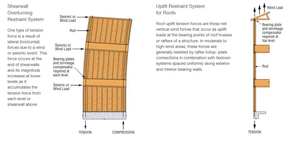
I’ll touch on some of the design considerations for these types of systems below, but back to the load path. For shearwall overturning restraint using holdowns, the load path is fairly simple. Once the lateral load is in the shearwall, the sheathing and nailing lifts up on the post. The holdown connects to the post, holding it down and transferring the forces to the foundation or level below. A continuous rod tiedown system follows a little different path. The sheathing and nailing lifts up on the boundary posts and the posts push up on the framing above until the load is resisted in bearing by a bearing plate. The load is then transferred into the rod and down to the foundation. There has been a lot of testing and research on the effects of skipping restraint locations where a bearing plate restraint is installed at every other floor or only at the top level. Doing that will change the load path because the load has to continue to travel up until a restraint holds it down. It also negatively impacts the stiffness and drift of the shearwall stack, not to mention increases project cost because the boundary posts, rod and bearing must be sized to transfer the cumulative overturning forces from each level.
Wood Shrinkage, Take-up Devices and Displacement Limits
Shrinkage is not just a Seinfeld episode cult classic. It is also something that designers need to consider when designing wood structures. IBC Section 2304.3.3 requires that designers evaluate the impact of wood shrinkage on the building structure when bearing walls support more than two floors and a roof. The effects of wood shrinkage can impact many things in the structure from finishes to MEP systems to the continuous rod system. As the wood members lose moisture, the wood shrinks and the building settles. This can cause gaps at the bearing plate locations of continuous rod systems because the continuous steel rod doesn’t shrink. That is where the magic of take-up devices comes in. They allow the building to shrink but keep gaps from forming by filling the gap (expanding devices – can be screw style or ratcheting), ratcheting down the rod (ratcheting devices), or making the rod shrink as much as the wood (contracting coupling device).
In addition to keeping the rod system tight to ensure the intended performance, it is important to consider the movement associated with the rod system when under wind or earthquake loading. The IBC requires shearwall displacements to be within story drift limits in moderate to high seismic regions. We highlighted some of the changes coming for the evaluation of shearwall deflection in the previous post discussing the New Treatment of Shear Wall Aspect Ratios in the 2015 SDPWS. For continuous rod systems, there are some additional limits. ICC-ES AC316 Acceptance Criteria for Shrinkage Compensating Devices requires designs to limit displacement between restraints to 0.20 inches (including rod elongation and device displacement) for shearwall restraint. The movement of the take-up device plays a big part in meeting this requirement and the rod diameter required. Screw-style devices have the lowest total movement. Ratcheting devices are appropriate in many cases as well such as the upper levels where loads are lower, but may require larger rod diameters to meet the displacement limit.
 ICC-ES AC391 Acceptance Criteria for Continuous Rod Tie-down Runs and Continuous Rod Tie-down Systems Used to Resist Wind Uplift covers continuous rod systems for roof uplift restraint. The displacement limit for the Continuous Rod Tie-down Run (just the rod system components) is limited to 0.18 inches of rod elongation for the total length of rod. The Strong-Rod URS evaluates the Continuous Rod Tie-down System (the whole load path). Displacement limits for the system are L/240 for the top plate bending and 0.25 inches total deflection at the top plate between tie-down runs (including top plate bending, rod elongation, wood bearing deformation and take-up device displacement). The differences between the rod run and rod system analysis as well as other design considerations are explained in more detail in the design guide and on our website.
I always end my continuous load path presentation during orientation class with the same questions and if they were paying attention I get the response I want.
“What is the most important thing a Structural Engineer does?”
“Designs a continuous load path for the building!”
“What does Simpson Strong-Tie do?”
“Provides product and system solutions to help engineers do their job!”
Take a look at the new Strong-Rod Systems tools and information and let us know how we can help you with your next multi-story wood-framed project.
What related blog topics would you like to discuss? Let us know in the comments below.

Holdown Anchorage Solutions
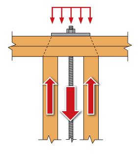
A common question we get from specifiers is “What anchor do I use with each holdown?” Prior to the adoption of ACI 318 Chapter 17, this was somewhat simple to do. We had a table that listed which anchor worked with each holdown.
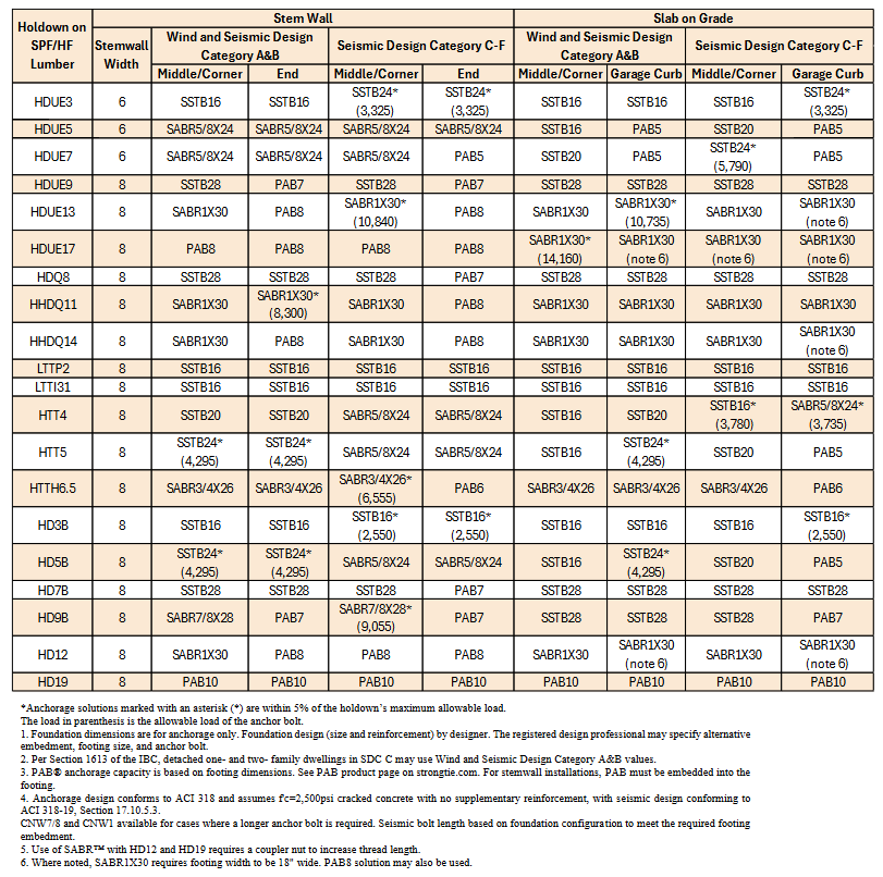
During the good old days, anchor bolts had one capacity and concrete wasn’t cracked. ACI 318 Chapter 17 gives us reduced capacities in many situations, different design loads for seismic or wind and reductions for cracked concrete. These changes have combined to make anchor bolt design more challenging than it was under the 1997 Uniform Building Code.
This blog has had several posts related to holdowns. So, What’s Behind a Structural Connector’s Allowable Load? (Holdown Edition) explained how holdowns are tested and load rated in accordance with ICC-ES Acceptance Criteria. Damon Ho did a post, Use of Holdowns During Shearwall Assembly, which discussed the performance differences of shearwalls with and without holdowns, and Shane Vilasineekul did a Wood Shearwall Design Example. So I won’t get in to how to pick a holdown.
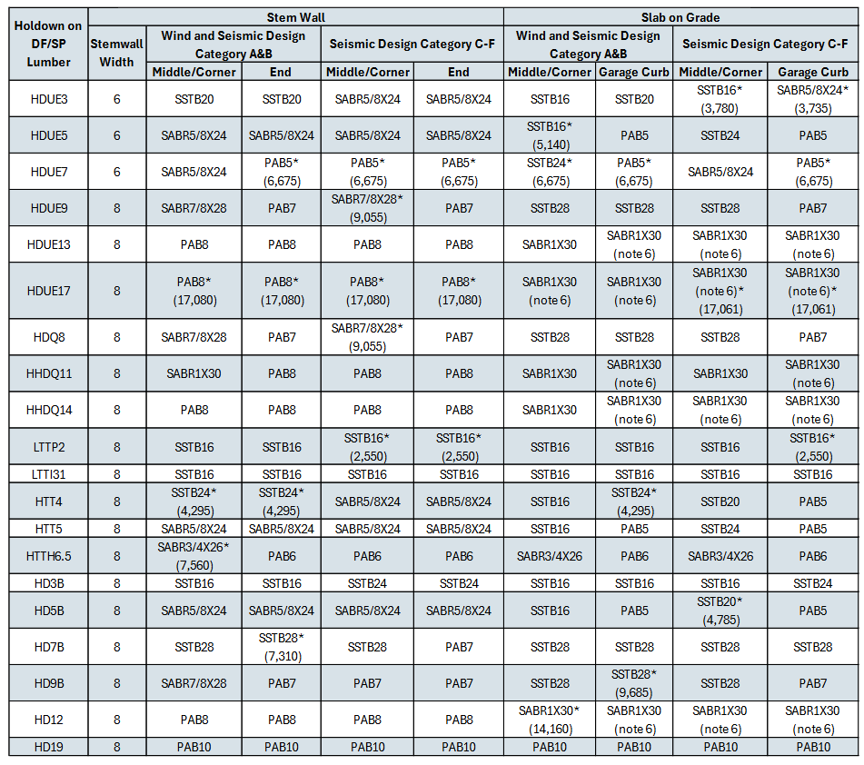
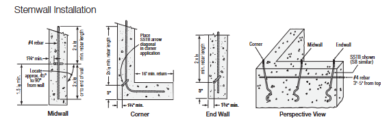
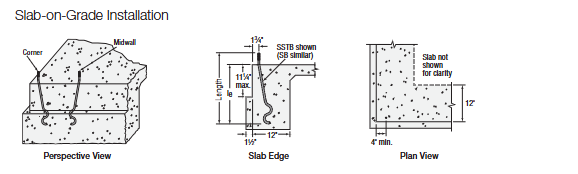
Once you have determined your uplift requirements and selected a post size and holdown, it is necessary to provide an anchor to the foundation. To help Designers select an anchor that works for a given holdown, we have created different tables that provide anchorage solutions for Simpson Strong-Tie holdowns.
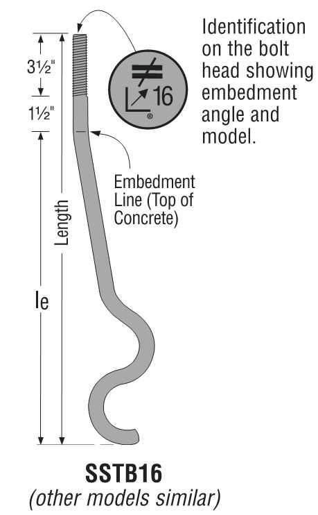
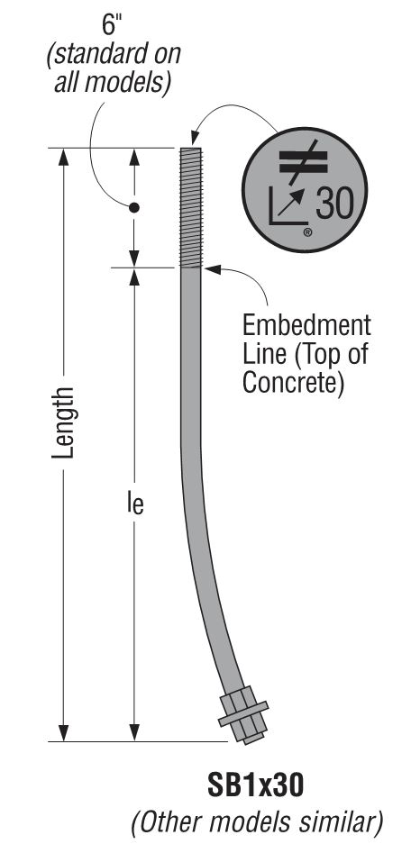
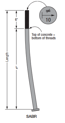
Our current catalog has addressed slab-on-grade, stemwall and grafe curb installation (DF/SP and SPF/HF) to give the most economical anchor design for each post material. The preferred anchor solutions are SSTB, SB or SABR anchors, as these proprietary anchor bolts are tested and will require the least amount of concrete. When SSTB, SB or SABR anchors do not have adequate capacity, we have tabulated solutions for the PAB anchors, which are pre-assembled anchors that are calculated in accordance with ACI 318 Chapter 17.
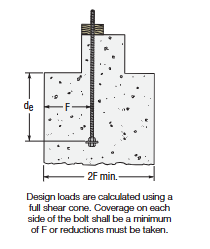
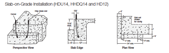
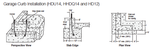
The solutions are designed to match the capacity of the holdowns, which allows the contractor to select an anchor bolt if the engineer doesn’t specify one. They are primarily used by engineers who don’t want to design an anchor or select one from our catalog tables. We received some feedback from customers who were frustrated that some of our heavier holdowns required such a large footing for the PAB anchors, whereas a slightly smaller holdown worked with an SSTB, SB or SABR anchor in a standard 12″ footing with a 1½” pop out.
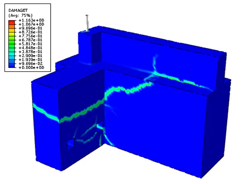
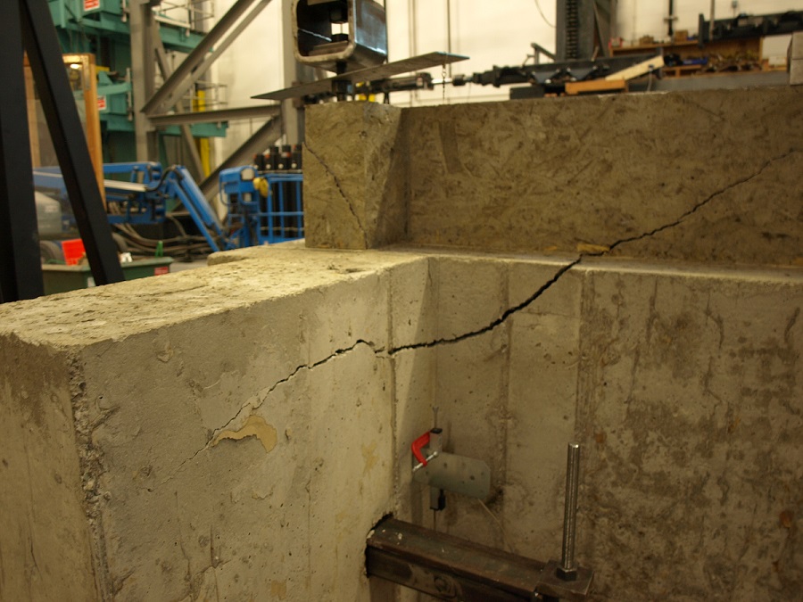
To achieve smaller footings using our SB1x30 and SABR1x30 anchor bolts, we reviewed our original testing and created finite element (FEA) models to determine what modifications to the slab-on-grade foundation details would meet our target loads. Of course, we ran physical tests to confirm the FEA models. With a 6″ pop out, we were able to achieve design loads for HD12, HDUE13, HHDQ14.
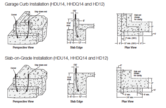
The revised footing solutions for the heavier holdowns require less excavation and less concrete than the previous Chapter 17 calculated solutions, reducing costs on the installation.
What has been your experience with holdown anchorage? Tell us in the comments below.

An Introduction to the Helical Wall Tie
What do you do when brickwork is in bad condition? Depending on what state the brickwork is in, a tear-down may be called for. However, often brickwork can be restored and strengthened using helical ties such as Simpson Strong-Tie® Heli-Tie™ wall ties and stitching ties. This post introduces these two types of helical ties, which might be just what you need for your next brick restoration project.

Which Tornado Saferoom is Right for You?

There certainly seems to be increased awareness of the potential for damage and injury from tornadoes these days. Recent information published by the Federal Emergency Management Agency (FEMA) and the Federal Alliance for Safe Homes (FLASH) help explain that. This increased awareness has led to a growing interest in tornado shelters for protection of life and property.
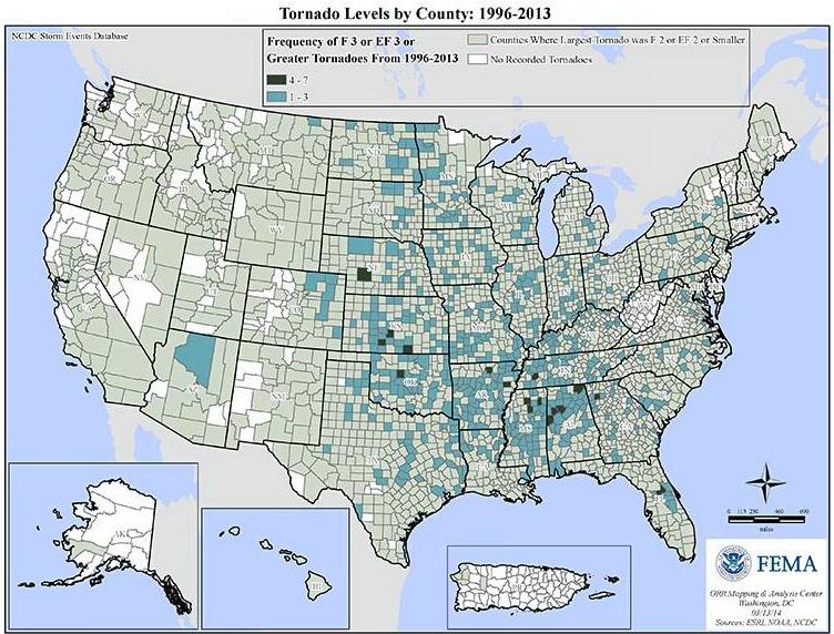
This FEMA graphic shows that most areas of the United States have been affected by a tornado at some point since 1996, and many have been affected by one or more strong tornadoes (EF3 or greater).
Living in North Texas near the Simpson Strong-Tie manufacturing plant in McKinney, Texas, I know all too well the sinking feeling of hearing the tornado sirens and turning on the TV to find you are under a tornado watch. FLASH recently published a graphic developed by the National Weather Service that shows the large number of U.S. counties that have been under a tornado watch between 2003-2014, and the high number of warnings that some counties experienced.
Other than moving to an area that has fewer tornadoes, one of the best ways to protect your family and at least have more peace of mind during tornado season is to have a tornado shelter or safe room. These structures are designed and tested to resist the highest winds that meteorologists and engineers believe occur at ground level during a tornado and the debris that is contained in tornado winds.
Tornado shelters can be either pre-fabricated and installed by a specialty shelter manufacturer, or can be site-built from a designed plan or pre-engineered plan. A good source for information on pre-fabricated shelters is the National Storm Shelter Association, a self-policing organization that has strict requirements for the design, testing and installation of its members’ shelters.
FEMA publishes a document, P-320, Taking Shelter from the Storm, that provides good information on safe rooms in general, as well as several pre-engineered plans for tornado safe rooms.
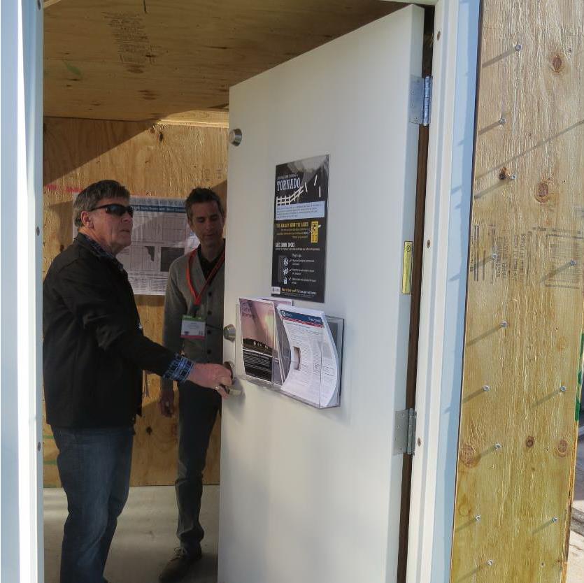
To highlight the different types of safe rooms covered by FEMA P-320, FEMA, FLASH and the Portland Cement Association (PCA) sponsored an exhibit at January’s International Builder’s Show. The exhibit was called the “Home Safe Home Tornado Saferoom Showcase.” It featured six different types of saferooms that builders could incorporate into the homes they build. Simpson Strong-Tie and the American Wood Council collaborated to build a wood frame with steel sheathing safe room meeting the FEMA P-320 plans. Other safe rooms shown at the exhibit included pre-cast concrete and pre-manufactured steel shelters manufactured by NSSA members, and reinforced CMU, ICF cast-in-place concrete and aluminum formed cast-in-place concrete built to FEMA P-320 plans.
Simpson Strong-Tie staff in McKinney, Texas, constructed the wood frame/steel sheathing safe room in panels and shipped it to the show. It was built from locally sourced lumber, readily available fasteners and connectors and sheets of 16 ga. steel (which we happen to keep here at the factory). It had cut-away sheathing at the corners to show the three layers of sheathing needed. Our message to builders was that this type of shelter would be the easiest for their framers to build on their sites.
The sponsors of the exhibit took advantage of the variety of safe rooms in one place to film a video series, “Which Tornado Safe Room is Right for You?” The videos are posted at the FLASH StrongHomes channel on YouTube. The series provides comparative information on cast-in-place, concrete block masonry, insulated concrete forms, precast concrete and wood-frame safe rooms, with the goal of helping consumers to better understand their tornado safe room options.
“Today’s marketplace offers an unprecedented range of high-performing, affordable options to save lives and preserve peace of mind for the millions of families in the path of severe weather,” said FLASH President and CEO Leslie Chapman-Henderson. “These videos will help families understand their options for a properly built safe room that will deliver life safety when it counts.”
FLASH released the videos earlier this month as part America’s PrepareAthon!, a grassroots campaign to increase community emergency preparedness and resilience through hazard-specific drills, group discussions and exercises. The overall goal of the program is to get individuals to understand which disasters could happen in their community, know what to do to be safe and mitigate damage from those disasters, take action to increase their preparedness, and go one step farther by participating in resilience planning for their community. Currently, the program focuses on preparing for the disasters of tornadoes, hurricanes, floods, wildfires, earthquakes and winter storms.
Do you know what the risk of disasters is in your community? If you are subject to tornado risk, would you like to build your own safe room, have one built to pre-engineered plans or buy one from a reputable manufacturer? Let us know in the comments below.
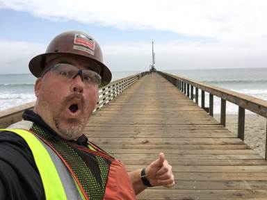
Pier Decking Fasteners
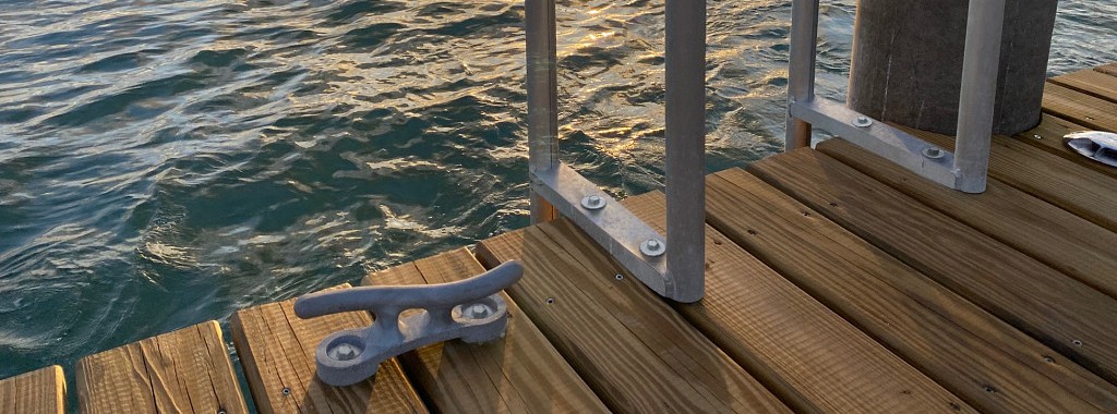
This week’s post is a case study featuring a recent restoration job on the central coast of California and how Simpson Strong-Tie® hot-dipped galvanized screws proved to be a better option than traditional spikes.
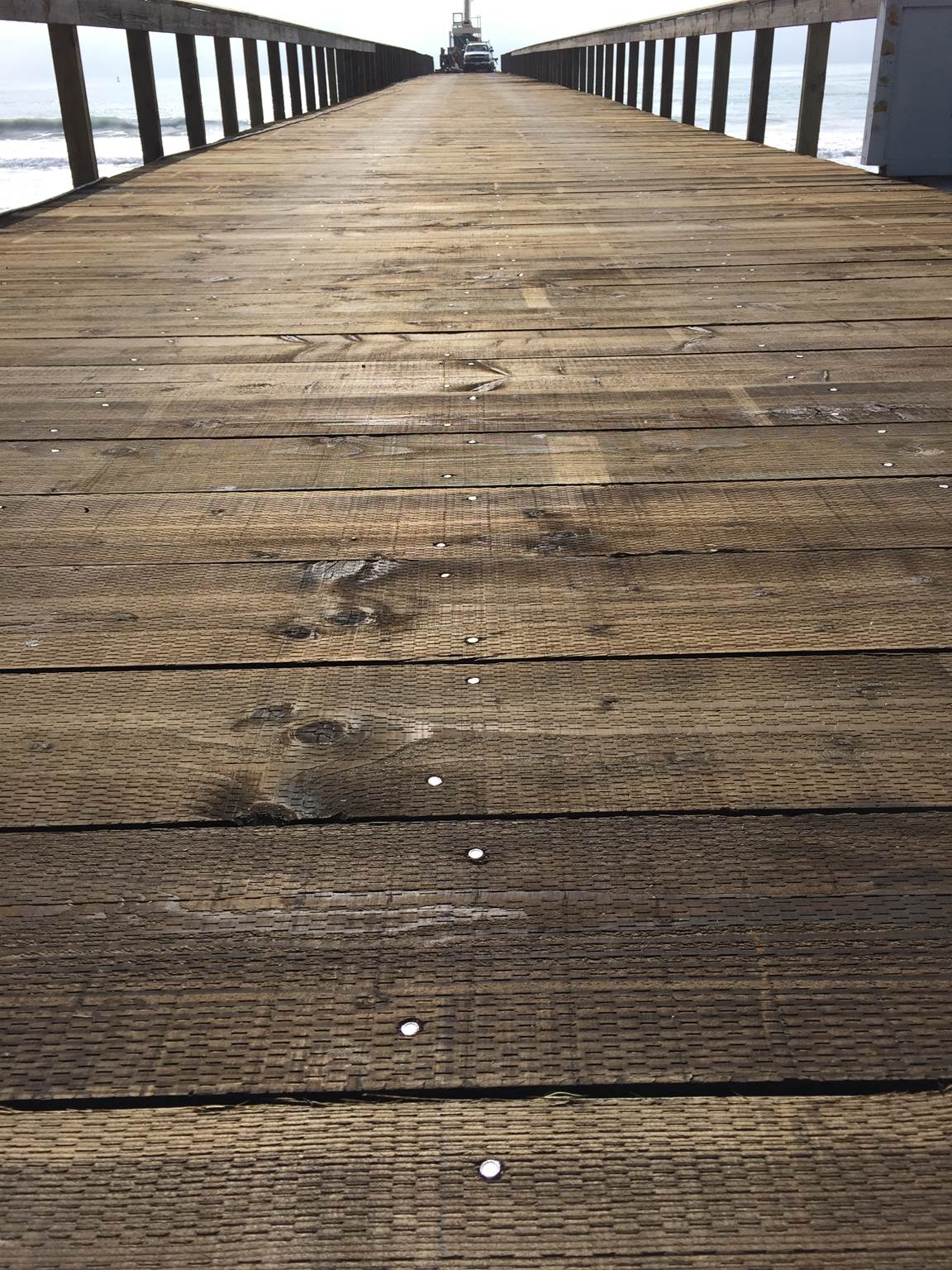
A pier originally constructed in the 1800s was closed a few years ago as general deterioration caused the structure to become unsafe. As preparation for rebuilding the pier began, one of the major concerns was the attachment of the deck boards to the framing.
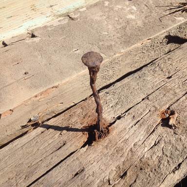
Traditionally, the deck boards have been attached with hot-dip galvanized 60d (0.283″ x 6″) spikes. However, spikes have a low withdrawal resistance, are typically predrilled and have a multi-step installation process. In addition, spikes, over time, can begin to back out so that the heads protrude above the top of the deck boards. This creates an unsafe condition for pedestrians and also results in ongoing maintenance work. Here you can see one of the old spikes.
Simpson Strong-Tie provided two options for replacing these spikes: the Strong-Drive® Timber-Hex HDG screw, SDWH27800G, and its stainless-steel counterpart, the Strong-Drive Timber-Hex SS screw, SDWH27800SS. The SDWH27800G screw measures 0.276″ x 8″ and has a hot-dip galvanized coating, conforming to ASTM A153 Class-C. The SDWH27800SS screw measures 0.276″ x 8″ and is made from Type 316 stainless steel. Both of these screws have integral washer, hex-drive heads and are self-drilling. They are not intended to be self-countersinking though, and as a result, installation with the heads below the deck surface requires a shallow dapped hole.
A comparison of the load values was provided to Shoreline Engineering, Inc. engineers Bruce S. Elster, P.E., and Jonathan T. Boynton, P.E., for their review and approval. In addition, Simpson Strong-Tie Fastening Systems/Dealer Sales Representative Darwin Waite expertly conducted on-site demonstrations for numerous decision makers including the contractor and city officials. These demonstrations allowed the contractor and owners to compare the labor costs and finished appearance of the different fastening methods.
Below is a comparison of the allowable load values* of the potential fasteners. We can see how each of the Simpson Strong-Tie screw options exceeds the spike load values in all load conditions.

*Not to be used for design purposes as footnotes have been left out of this blog post. Table values include wet service factor adjustments.
In the end, the SDWH27800SS stainless-steel screw was specified for the project.
Some might consider a 316 stainless steel screw to be cost prohibitive, but when you factor in the lower cost of installation, the lower maintenance requirements and the actual cost of the fastener, this screw turned out to be the lowest cost alternate. In addition, it provided better withdrawal and lateral load values than the spikes.

The Strong-Drive Timber-Hex SS screws made it possible to complete the deck restoration on time and on budget. Perhaps just as importantly, the pier looks beautiful and should last for many years to come.
Let us know if the comments below if you have any questions about specifying these fasteners for securing decks, docks, pilings and other heavy-duty, coastal applications.
As always, call our Engineering Department if you have any questions.
Have you used the SDWH27800SS screw for a project? Tell us about in the comments below.