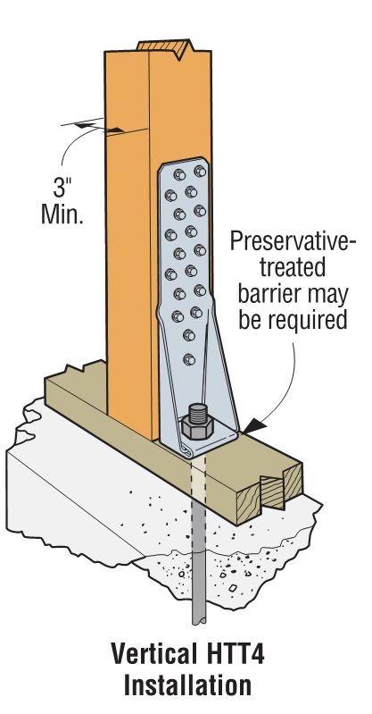
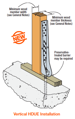
Keith Cullum started off our “How to Select a Connector” series with Hurricane Ties. This week we will discuss how to select holdowns and tension ties, which are key components in a continuous load path. They are used to resist uplift due to shearwall overturning or wind uplift forces in light-frame construction. In panelized roof construction, holdowns are used to anchor concrete or masonry walls to the roof framing.
Holdowns can be separated in two basic categories – post-installed and cast-in-place. Cast-in-place holdowns like the STHD holdowns or PA purlin anchors are straps that are installed at the time of concrete placement. They are attached with nails to wood framing or with screws to CFS framing. After the concrete has been placed, post-installed holdowns are attached to anchor bolts at the time of wall framing. The attachment to wood framing depends on the type of holdowns selected, with different models using nails, Simpson Strong-Tie® Strong-Drive® SDS Heavy-Duty Connector screws or bolts.
A third type of overturning restraint is our anchor tiedown system (ATS), which is common in multistory construction with large uplift forces. I discussed the system in this blog post.
Given the variety of different holdown types, a common question is, how do you choose one?
For prescriptive designs, such as the IRC portal frame method, the IRC or IBC may require a cast-in-place strap-style holdown. Randy Shackelford did a great write-up on the PFH method in this post.
For engineered designs, a review of the design loads may eliminate some options and help narrow down the selection.
Holdown Type
Maximum Load (lb.)
Cast-in-Place
5,300
Nailed
5,090
SDS Screws
17,685
Bolted
19,070
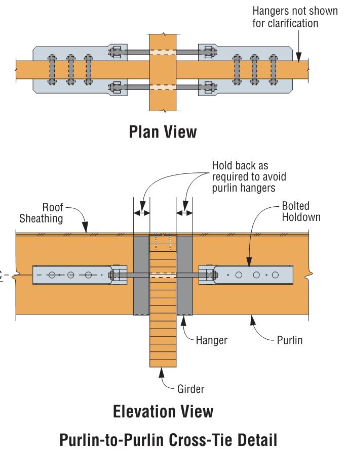
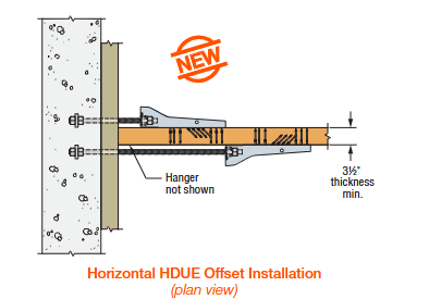
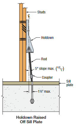
Adjustability should be considered when choosing between a cast-in-place and a post-installed holdown. Embedded strap holdowns are economical uplift solutions, but they must be located accurately to align with the wood framing. If the anchor bolt is located incorrectly for a post-installed holdown, raising the holdown up the post can solve many problems. And anchors can be epoxied in place for missing anchor bolts.
We are often asked if you can double the load if you install holdowns on both sides of the post or beam. The answer is yes, and this is addressed in our holdown general notes.
Nailed or screwed holdowns need to be installed such that the fasteners do not interfere with each other. Bolted holdowns do not need to be offset for double-sided applications. Regardless of fastener type, the capacity of the anchorage and the post or beam must be evaluated for the design load.
Once you have selected a holdown for your design, it is critical to select the correct anchor for the demand loads. Luckily, I wrote a blog about Holdown Anchorage Solutions last year. What connector would you like to see covered next in our series? Let us know in the comments below.
Back in the year 2000, the U.S. Department of Defense (DoD) was charged with incorporating antiterrorism protective features into the planning, design and execution of its facilities. The main document developed to meet this requirement is the Unified Facilities Criteria “DoD Minimum Antiterrorism Standards for Buildings” (UFC 4-010-01). The current version was published in December 2018, with subsequent updates through Change 3 (May 2024). This document covers what is most commonly referred to as “blast” design.Continue Reading
Five Simpson Strong-Tie employees had the opportunity to participate in a week-long Habitat for Humanity build in the small town of Amarante, Portugal, in late April. The company decided to allocate the funds for the CWP to Habitat’s Global Village program, allowing these employees to help renovate and remodel the older home of a widowed mother (Doña Margarida Ribiero) and daughter (Sonia) living in the Portuguese countryside.
Five Simpson Strong-Tie employees had the opportunity to participate in a week-long Habitat for Humanity build in the small town of Amarante, Portugal, in late April. The group was originally scheduled to work on a Habitat project in Nepal late last year as part of Habitat’s Jimmy and Rosalynn Carter Work Project (CWP), but following the signing of a new constitution and civil unrest in the country, the project was canceled.Continue Reading
In last week’s blog post, we introduced the Simpson Strong-Tie® Strong-Wall® Wood Shearwall. Let’s now take a step back and understand how we evaluate a prefabricated shear panel to begin with.
First, we start with the International Building Code (IBC) or applicable state or regional building code. We would be directed to ASCE7 to determine wind and seismic design requirements as applicable. In particular, this would entail determination of the seismic design coefficients, including the response modification factor, R, overstrength factor, Ωo, and deflection amplification factor, Cd, for the applicable seismic-force-resisting system. Then back to the IBC for the applicable building material: Chapter 23 covers Wood. Here, we would be referred to AWC’s Special Design Provisions for Wind and Seismic (SDPWS) if we’re designing a lateral-force-resisting system to resist wind and seismic forces using traditional site-built methods.Continue Reading
The ICC says that “Building Safety Month is a public awareness campaign to help individuals, families and businesses understand what it takes to create safe and sustainable structures. The campaign reinforces the need for adoption of modern, model building codes, a strong and efficient system of code enforcement and a well-trained, professional workforce to maintain the system.” Building Safety Month has a different focus each week for four weeks. Week One is “Building Solutions for All Ages.” Week Two is “The Science Behind the Codes.” Week Three is “Learn from the Past, Build for Tomorrow.” Finally, Week Four is “Building Codes, A Smart Investment.” Simpson Strong-Tie is proud to be a major sponsor of Week Three of Building Safety Month.
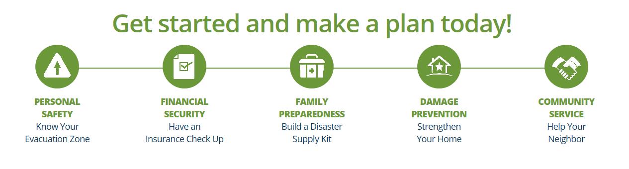
National Hurricane Preparedness Week is recognized each year to raise awareness of the threat posed to Americans by hurricanes. A Presidential Proclamation urged Americans to visit www.Ready.gov and www.Hurricanes.gov/prepare to learn ways to prepare for dangerous hurricanes before they strike. Each day of the week has a different theme. The themes are:
⦁ Determine your risk; develop an evacuation plan
⦁ Secure an insurance check-up; assemble disaster supplies
⦁ Strengthen your home
⦁ Identify your trusted sources of information for a hurricane event
⦁ Complete your written hurricane plan.
This week also marks the NOAA Hurricane Awareness Tour, where NOAA hurricane experts will fly with two of their hurricane research aircraft to five Gulf Coast Cities. Members of the public are invited to come tour the planes and meet the Hurricane Center staff along with representatives of partner agencies. The goal of the tour is to raise awareness about the importance of preparing for the upcoming hurricane season. The aircraft on the tour are an Air Force WC-130J and a NOAA G-IV. These “hurricane hunters” are flown in and around hurricanes to gather data that aids in forecasting the future of the storm. As with Hurricane Preparedness Week, each day of the tour features a different theme. Simpson Strong-Tie is pleased to be a sponsor for Thursday, when the theme is Strengthen Your Home. Representatives from Simpson Strong-Tie will be attending the event on Thursday to help educate homeowners on ways to make their homes safer.
Finally, this week is the official kickoff of a new hurricane resilience initiative, HurricaneStrong. Organized by FLASH, the Federal Alliance for Safe Homes and in partnership with FEMA, NOAA and other partners, the program aims to increase safety and reduce economic losses through collaboration with the most recognized public and private organizations in the disaster safety movement. HurricaneStrong is intended to become an annual effort, with activities starting prior to hurricane season and continuing through the end of the hurricane season on November 30. To learn more, visit www.hurricanestrong.org.
Experts consider these public education efforts to be more important every year, as it becomes longer since landfall of a major hurricane and as more and more people move to coastal areas. The public complacency bred from a lull in major storms has even been given a name: Hurricane Amnesia.
All these efforts may be coming at a good time, assuming one of the hurricane season forecasts is correct. A forecast from North Carolina State predicts an above-average Atlantic Basin hurricane season. On the other hand, forecasters at the Department of Atmospheric Science at Colorado State University are predicting an approximately average year.
Are you prepared for the natural hazards to which your geographic area is vulnerable? If not, do you know where to get the information you need?
Some contractors and framers have large hands, which can pose a challenge for them when they’re trying to install the holdown nuts used to attach our Strong-Wall® SB (SWSB) Shearwall product to the foundation. Couple that challenge with the fact that anchorage attachment can only be achieved from the edges of the SWSB panel, and variable site-built framing conditions can limit access depending upon the installation sequence. To alleviate anchorage accessibility issues, we’ve required a gap between the existing adjacent framing and SWSB panel equal to the width of a 2x stud to provide access so the holdown nut can be tightened. Even so, try telling a framer an inch and a half is plenty of room in which to install the nut!Continue Reading
This week’s post was written by Kevin Gobble of Habitat for Humanity. Kevin is the Program Manager for Habitat for Humanity’s new Habitat Strong initiative. Kevin has spent over 22 years in residential construction building energy-efficient, high-performing home, and has consulted with several sustainable building programs on ways to develop their own best practices. As a third-generation builder, he has knowledge in the field of residential building science and has furthered his education to include many industry certifications — NARI Certified Remodeler, NAHB Certified Green Professional, RESNET Certified Green Rater, BPI Building Analyst, FORTIFIED evaluator, and Level 1 Infrared Thermography — while working directly with industry partners to focus on cost-effective construction solutions. Kevin has built and remodeled numerous homes to high-performance standards as certified by various building programs, including his latest project for himself: converting a condemned historic property in Atlanta to EarthCraft House Platinum.
In a previous blog post, we discussed the background of the Habitat Strong program. Habitat Strong promotes the building of resilient homes that are better equipped to withstand natural disasters in every region of the country. This program uses IBHS FORTIFIED Home™ standards and works well within Habitat’s model of building affordable, volunteer-friendly homes.Continue Reading
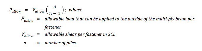
Larger beams are often built up out of smaller 2x or 1¾” members. This can be done for several different reasons: for the convenience of handling smaller members on the jobsite, or because solid 4x, 6x or glulam material is not readily available, or for reasons of cost. Engineered wood such as laminated veneer lumber (LVL) is often used for its high load capacity and multiple 1¾” plies are built up to get the required capacity for the application.
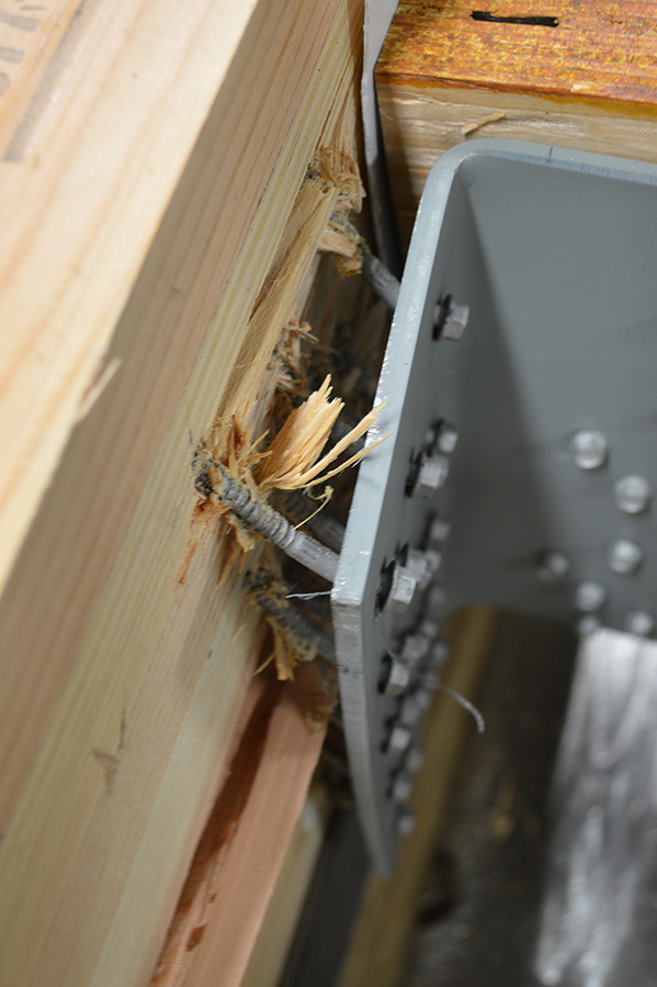
8-Ply LVL Beam in HHGU14 Test
When a built-up beam is loaded concentrically as in the test setup shown, fastening the members is not critical since that giant steel plate will load each ply of the beam. In the field, built-up beams or girders commonly support joists or beams framing into their side. The built-up members must be connected to transfer load from the loaded ply into the other plies.
Allowable Uniform Loads and Spacing Requirements
Page 124 of our Fastening Systems Technical Guide, C-F-2025TECHSUP provides allowable uniform load tables for side-loaded multi-ply assemblies using LVL, PSL or LSL material. The calculation for the allowable load applied to the outside ply of a multi-ply beam is:
While uniform loads are very common, Designers often request additional information to design multi-ply beam connections to transfer concentrated loads. Simpson Strong-Tie has created a new engineering letter, L-F-SDWMLTPLY16, which complements the information in the Fastening Systems catalog by providing allowable loads in a single fastener format. Designers can use the information to calculate the number of fasteners required for a given point load.
Simpson Strong-Tie® Strong-Drive® SDW EWP-Ply Screw – Allowable Loads for Side-Loaded Multi-Ply Assemblies per Screw
In order to ensure load transfer, the SDW screws need to be located relatively close to the connection. At first glance, it may appear challenging to fit enough fasteners while meeting the non-staggered row-spacing requirements. However, we have found that most loads can be managed by taking advantage of the ⅝” stagger allowance.
SDW – Maximum Fastener Spacing from Point Load
If you are curious what happened in that HHGU14 test, the screws pulled out of the header with a load slightly exceeding 101,000 pounds. Failure photo 2 shows a close-up of the pullout failure. The tested load was very close to the maximum calculated capacity for the SDS screws in the connector, so it was a great test result. What are your thoughts? Let us know in the comments below.
Did you know that Simpson Strong-Tie is celebrating its 60th birthday this year? We started out with one punch press and the ability to bend light-gauge steel. Then, one Sunday evening in the summer of 1956, Barclay Simpson’s doorbell rang and a request for our first joist hanger led us into the wood connector business. Since then, we’ve continued to grow that business by focusing on our engineering, research and development efforts. Some might say that nowadays we’re an engineering company that also happens to manufacture products, as evidenced by our focus on developing technology tools over the past few years such as web calculators, an updated website and design software. Our focus on technology, however, is really another aspect of our continued commitment to excellence in manufacturing and our application of the tenets of lean manufacturing.
Many of you may already be familiar with the idea of lean manufacturing made famous by Toyota in the early 2000s, along with the principles of continual improvement and respect for people. The concept of continual improvement is based on the idea that you can always make small changes to improve your processes and products. Although they were established in a manufacturing setting, these ideals ring very true for engineering as well; eliminate steps in your design process that don’t add any value to the final project and always be on the lookout for tools or techniques that can speed up your process. Thinking lean isn’t about cutting corners to get your result faster, it’s about mindfully getting rid of the steps that aren’t helping you and finding better ways of doing everyday tasks.
As structural engineers, we can find ourselves working on a variety of projects that lead us to perform repetitive calculations to check different conditions, such as varying parapet heights on the exterior of a building, or we may find ourselves working with an unfamiliar material, such as light-gauge or cold-formed steel (CFS), where we have to take some time away from design to review reference materials such as AISI S200-12 North American Standard for Cold-Formed Steel Framing. Wouldn’t it be great if there were a design tool that could help you complete your light-gauge projects more quickly, in complete compliance with current building codes?
It turns out that Simpson Strong-Tie offers a design tool called CFS Designer™ to help structural engineers improve their project design flow. This program gives engineers the ability to design light-gauge stud and track members with complex beam loading and span conditions according to building code specifications. What does that actually mean, though? Allow me to illustrate with an example of a design project.
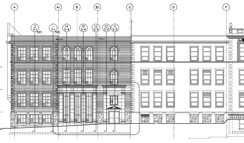
Let’s say you’re designing a building and part of your scope is the exterior wall framing, or “skin” of the building. You probably get sent some architectural plans that look something like this:
Figure 1. Sample building elevation with section marks.
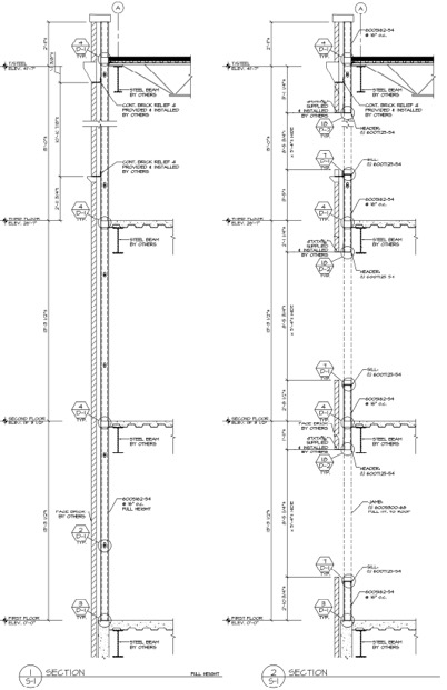
The architectural elevations will have wall section marks indicated for different framing situations. Two sample wall sections are shown in Figure 2.
Figure 2. Sample building wall sections.
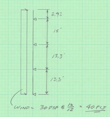
This building has several different wall section types that include door and window locations, varying parapet heights, diverse finish materials that need to meet different deflection criteria, and different connection points back to the base building. The traditional design calculation that you would need to run for one wall section might begin with a loading diagram similar to Figure 3 below.
Figure 3. Sample calculation of wall stud loading diagram.
Once you have your loading diagram generated, you would need to use reference load tables or a computer analysis program to solve for the axial and moment demands, the reactions at the pinned supports, and the member deflections.
After you determine the demand loads, you would then need to select a CFS member with sufficient properties, and you may need to iterate a few times to find a solution that meets the load and deflection parameters. After you’ve selected a member with the right width, gauge and steel strength, you’ll need to select an angle clip that can handle the demand loads, as well as fasteners to connect the clip to the CFS stud and to the base building. You would also need to also check the member design to ensure that it complies with bridging or bracing requirements per AISI. Then, after all that, you’d have to repeat the process again for all of the wall section types for your project.
Figure 4. Hmm, CFS design would sure be a lot easier if buildings were just huge windowless boxes…
Just writing out that whole process took some time, and you can imagine that actually running the calculations takes quite a bit longer. I think we can all agree that the design process we’ve outlined is time-consuming, and here’s where using CFS Designer™ to streamline your design process can really help.
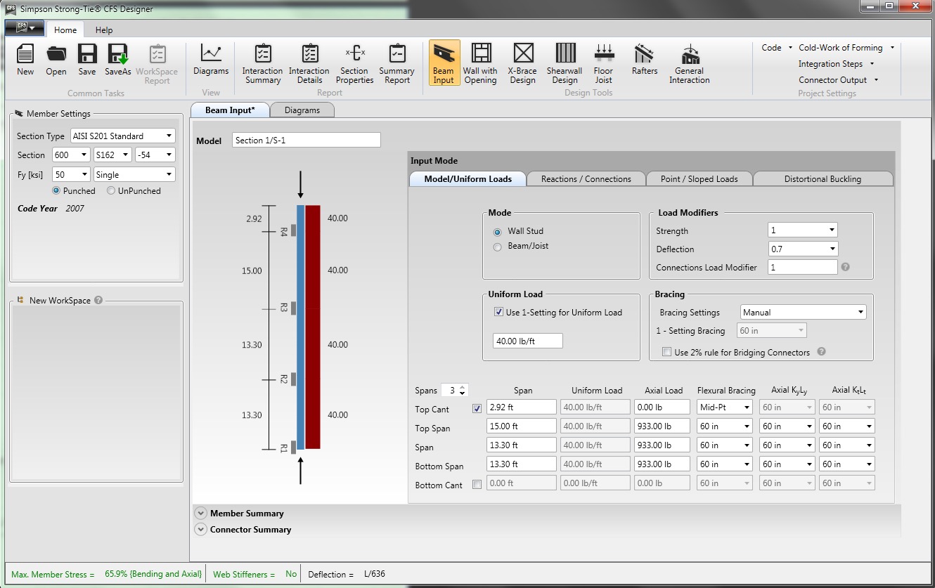
CFS Designer is a structural engineering design program that can automate many of the manual steps that are required in the design process. It has an easy-to-understand graphical user interface that allows you to input your project parameters within a variety of design modules from walls and beams, jambs and headers, X-brace walls, shearwalls, floor joists, and roof rafters. The program also enables the design of single stud or track members, built-up box-sections, back-to-back sections, and nested stud or track sections. Figure 5 shows an example of how you would input the same stud we looked at before into the program.
Figure 5. CFS Designer™ user interface for wall stud design.
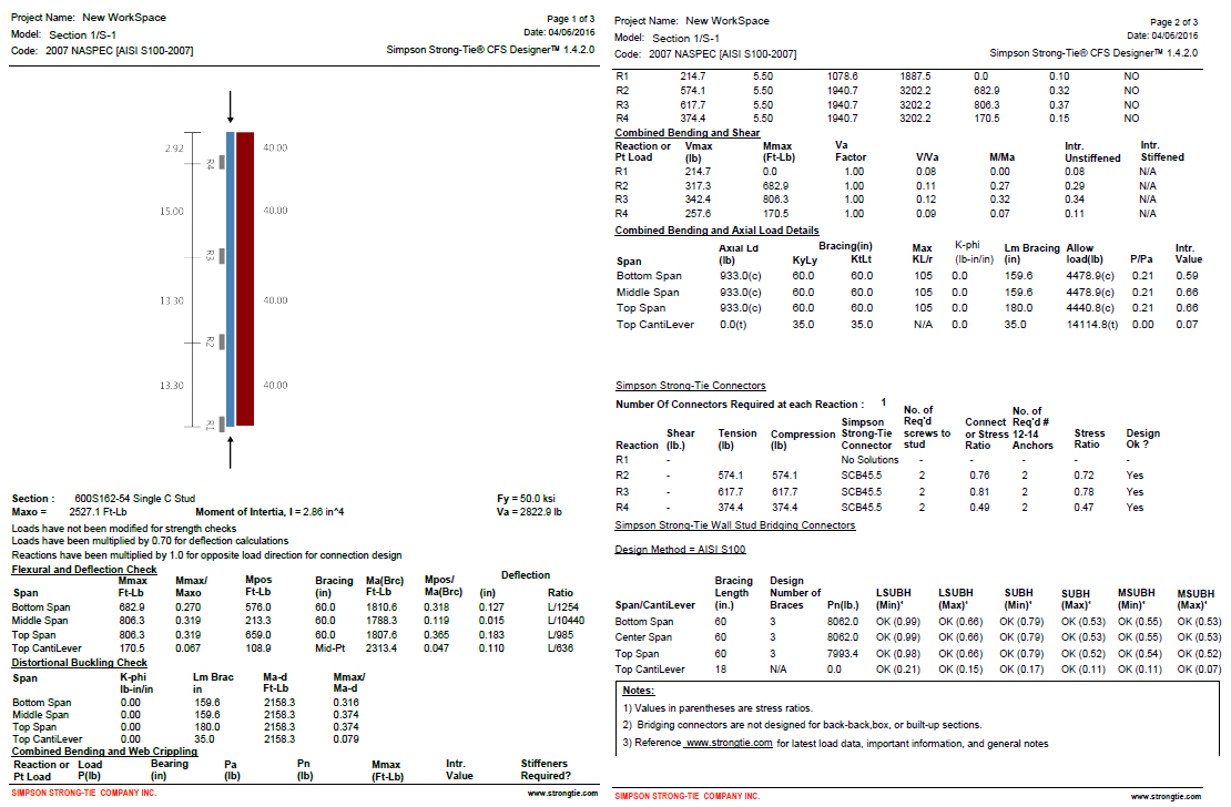
The program will generate the loading diagrams and complete calculation package for all of these different situations. And along with checking the member properties and deflection limits, CFS Designer will also check bridging and bracing requirements and provide connector solutions for the studs using tested and code-listed Simpson Strong-Tie products. Figure 6 shows an example of the summary output you would receive.
Figure 6. The comprehensive summary output page that covers the complete member design down to the bracing and connection solutions.
One unique part of the output is toward the center of the second page, under the heading “Simpson Strong-Tie Connectors.” This section summarizes the tension and compression loads at each reaction point and then shows a connector solution (such as the SCB45.5) along with the number of screws to the stud and the number of #12 sheet-metal screws to anchor back to the base building. Simpson Strong-Tie has developed and tested a full array of connectors specifically for CFS curtain-wall construction as well as for interior tenant improvement framing, which allows designers to select a connection clip straight out of a catalog without needing to calculate their own designs per the code. It’s just another way we’re helping you to get a little leaner!
The last part of the output shown in Figure 6 is titled “Simpson Strong-Tie Wall Stud Bridging Connectors.” It checks the bridging and bracing requirements per AISI S100 and selects a SUBH bridging connector, an innovative bridging solution developed by Simpson Strong-Tie that snaps into place and achieves design loads while only requiring one #10 screw to connect for 75% of applications.
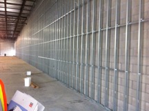
Figure 8. A close-up of the SUBH installed (left) and a wall of studs with bridging installed using the LSUBH clips (right).
You can download a free trial of CFS Designer™ and give it a test drive to see how much time it can save you on a design project. The trial version has almost full functionality, with the exception of not being able to print the output sheets. You can see purchasing information online, and you should always feel free to contact your local Simpson Strong-Tie engineering department with any questions you may have. I hope you are able to take advantage of this great tool to further improve your everyday design processes. We will be sure to keep you updated on our latest technology tools that help speed up the design process. If you’re using CFS Designer, we’d like to hear your thoughts about the program. Please share them in the comments below.
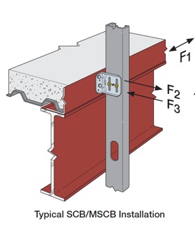
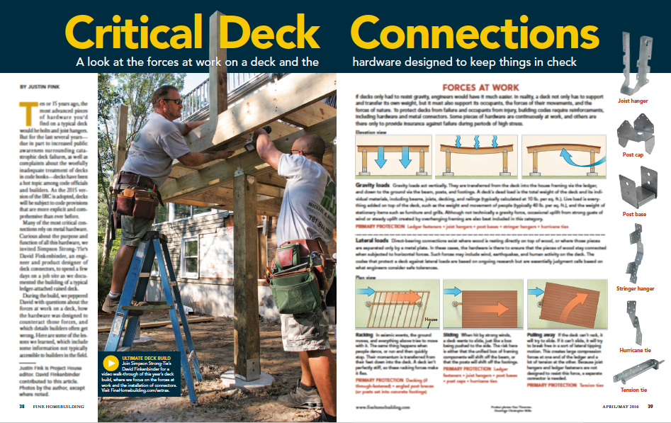
We’re partnering with folks at Fine Homebuilding on a video series on how to build a deck that is code compliant and that highlights the critical connections of a deck. This series is called Ultimate Deck Build 2016. The video series comprises five videos that walk professionals through the recent code changes for the key connections of a deck.
The series features David Finkenbinder, P.E., a branch engineer for Simpson Strong-Tie who is passionate about deck codes and safety. He offers information on load resistance and the hardware that professionals can use at the crucial connections to make a deck code compliant. “This was a great opportunity to collaborate with the team at Fine Homebuilding, to communicate the connections on a typical residential deck and the role that they serve to develop a strong deck structure,” said David. “These same connections would also likely be common in similar details created by an Engineer, when designing a deck per the International Building Code (IBC).”
The videos are being released every Wednesday during the month of March and feature the following deck connections:
Ledger Connection: This is the primary connection between a deck and a house. David tells the Fine Homebuilding team about various code- compliant options for attaching a deck ledger to a home.
Beam and Support Posts: David explains how connectors at this critical point can prevent uplift and resist lateral and downward forces. He also discusses footing sizes and post-installation anchor solutions.
Joists: This video reviews proper joist hanger installation and the benefits of installing hurricane ties between the joists and the beams. David goes into common joist hanger misinstallations, such as using the wrong fasteners or using a joist hanger at the end of a ledger.
Guardrail Posts: David reviews the different ways that you can attach a guardrail post so as to resist an outward horizontal load.
Stairs: David explains code-compliant options for attaching stringers to a deck frame.
Make sure to watch the series and let us know what you think. For more information, Fine Homebuilding has created an article titled “Critical Deck Connections.”
(Please note: this article is member-only/subscription content, so to read it you’ll need to either subscribe online or pick up the April/May issue of Fine Homebuilding.)
We use cookies on this site to enhance your user experience. By clicking "I AGREE" below, you are giving your consent for us to set cookies. Privacy PolicyI AGREE
Privacy & Cookies Policy
Privacy Overview
This website uses cookies to improve your experience while you navigate through the website. Out of these cookies, the cookies that are categorized as necessary are stored on your browser as they are essential for the working of basic functionalities of the website. We also use third-party cookies that help us analyze and understand how you use this website. These cookies will be stored in your browser only with your consent. You also have the option to opt-out of these cookies. But opting out of some of these cookies may have an effect on your browsing experience.
Necessary cookies are absolutely essential for the website to function properly. This category only includes cookies that ensures basic functionalities and security features of the website. These cookies do not store any personal information.
Any cookies that may not be particularly necessary for the website to function and is used specifically to collect user personal data via analytics, ads, other embedded contents are termed as non-necessary cookies. It is mandatory to procure user consent prior to running these cookies on your website.


 Given the variety of different holdown types, a common question is, how do you choose one?

 We are often asked if you can double the load if you install holdowns on both sides of the post or beam. The answer is yes, and this is addressed in our holdown general notes.