


“From a seismological standpoint, Northridge was not a big earthquake.” This is first sentence of the “Resilience by Design” report by L.A. Mayor’s Seismic Safety Task Force led by Dr. Lucy Jones of the U.S. Geological Survey (USGS). The report is the culmination of a year-long investigation into the greatest vulnerabilities of the city from a major seismological event. Continue Reading
Tag: Simpson Strong-Tie

Seismic Safety Regulations and Solutions
I have a special place in my heart for old buildings. Every college design course I took was related to new design. Concrete, steel, or wood design, the design problem was invariably part of a new building. I thought structural engineers designed new buildings. When I showed up for my first day of work wearing dress pants, a button-down shirt and a tie, I was handed a flashlight, tape measure, a clipboard and a Thomas Guide map (no Google maps back then) and sent to do as-built drawings for a concrete tilt-up that we were retrofitting.
When I was designing buildings, I created a lot of as-built drawings. Figuring out how a building was put together, what the structural system was (or wasn’t!) and designing a lateral load path in these old, and often historic buildings, was immensely satisfying. Knowing that history, it should not be surprising I have done a number of blog posts related to seismic retrofits. Soft-Story Retrofits, San Francisco’s Soft-Story Retrofit Ordinance, Remembering Loma Prieta, Resilient Communities, FEMA P-807, and Home Seismic Retrofit (there are probably a couple I forgot).
This week, Los Angeles Mayor Eric Garcetti proposed new seismic safety regulations . The recommendations are to retrofit soft-story wood-framed buildings within five years and older concrete buildings within 30 years. While these are only recommendations, it is encouraging to see politicians supporting policies to promote resiliency and life safety.
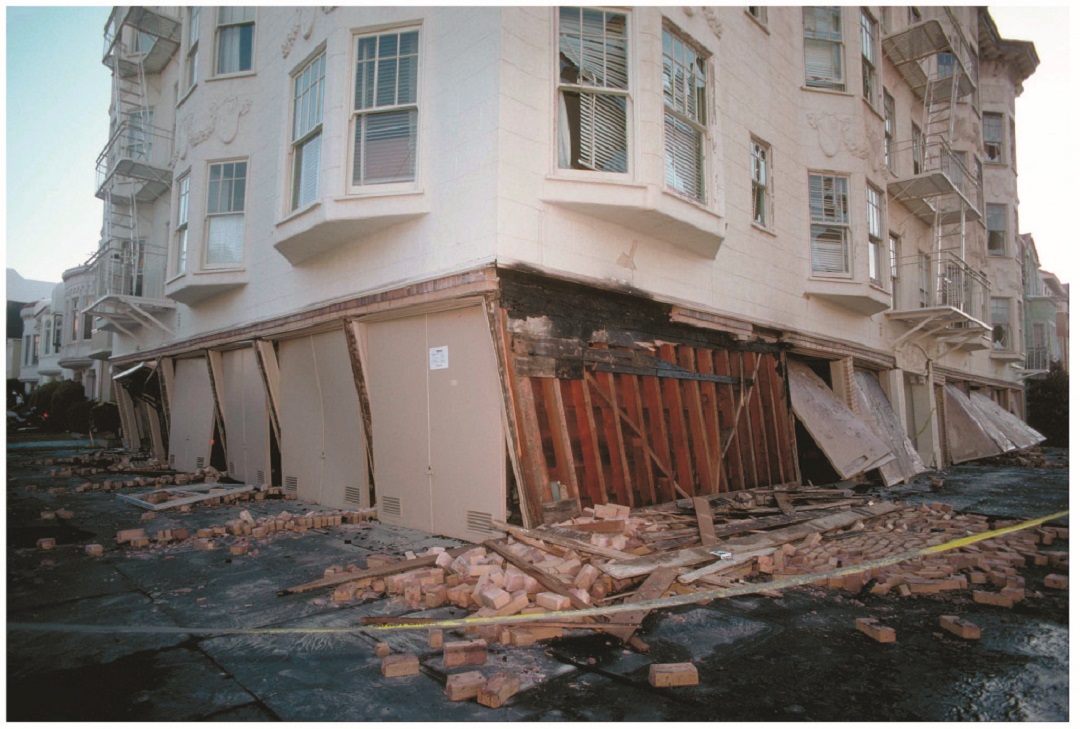
In San Francisco, thousands of building owners are already required by law to seismically retrofit multi-unit (at least five) soft-story, wood-frame residential structures that have two or more stories over a “soft” or “weak” story. These buildings typically have parking or commercial space on the ground floor with two or more stories above. As a result, the first floor has far more open areas of the wall than it actually has sheathed areas, making it particularly vulnerable to collapse in an earthquake.
San Francisco’s ordinance affects buildings permitted for construction before Jan. 1, 1978. Mandatory seismic retrofit program notices requiring that buildings be screened were sent out in September, 2013, to more than 6,000 property owners. It is anticipated that approximately 4,000 of those buildings will be required to be retrofitted by 2020.
“When we look at the demographic of these buildings, they house approximately 110,000 San Franciscans. It’s paramount that we have housing for people after a disaster. We know we will see issues in all types of buildings, but this is an opportunity for us to be able to retrofit these buildings while keeping an estimated 1100,000 San Franciscans in their homes and, by the way of retrofit, allowing them to shelter in place after a disaster,” according to Patrick Otellini, San Francisco’s chief resilience officer and director of the city’s Earthquake Safety Implementation Program. “This exponentially kick starts the city’s recovery process.”
One solution to strengthen such buildings is the Simpson Strong-Tie® Strong Frame® special moment frame. Its patented Yield-Link™ structural fuses are designed to bear the brunt of lateral forces during an earthquake, isolating damage within the frame and keeping the structural integrity of the beams and columns intact.
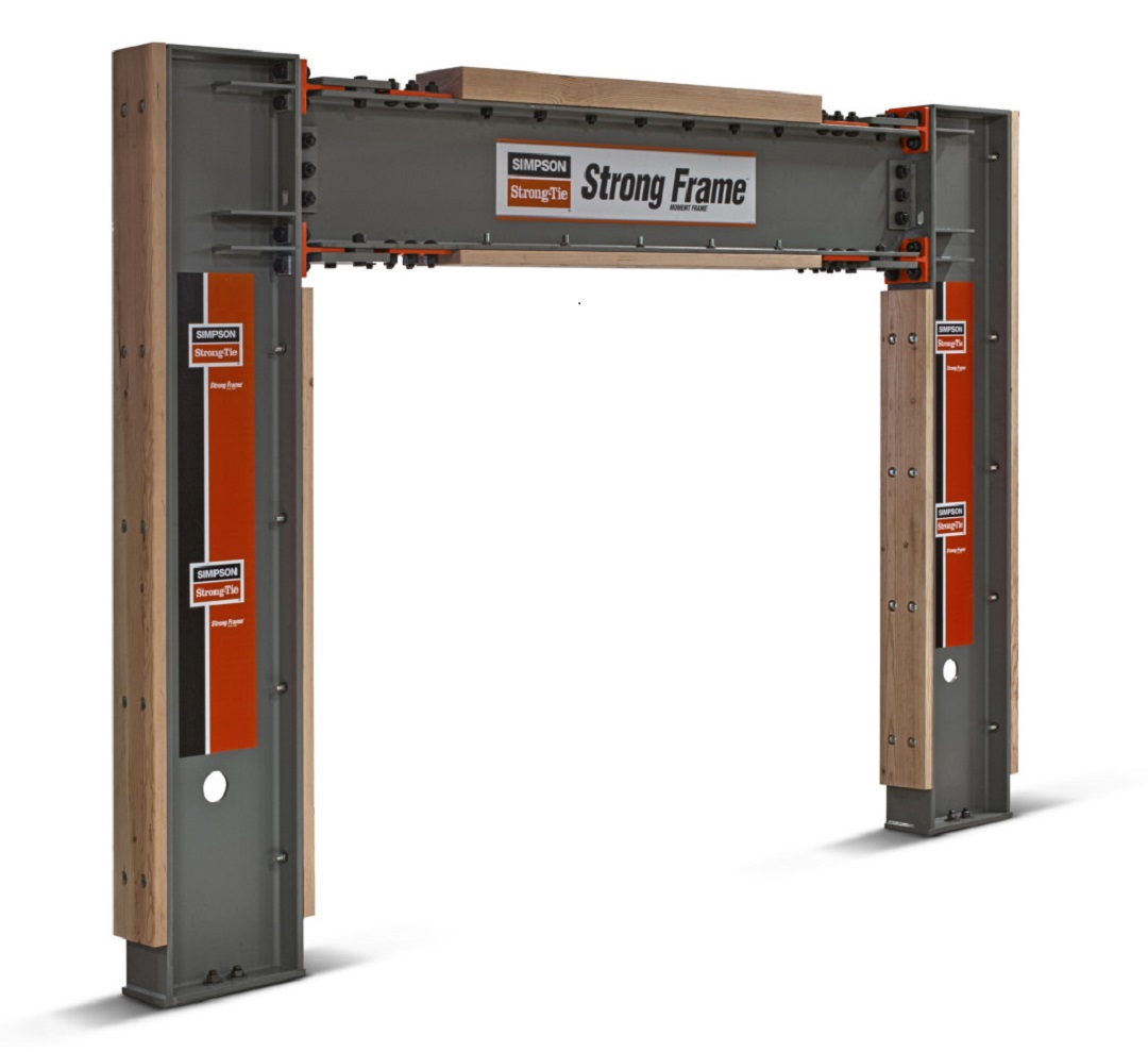
“The structural fuses connect the beams to the columns. These fuses are designed to stretch and yield when the beam twists against the column, rather than the beam itself, and because of this the beams can be designed without bracing. This allows the Strong Frame to become a part of the wood building and perform in the way it’s supposed to,” said Steve Pryor, S.E., International Director of Building Systems at Simpson Strong-Tie. “It’s also the only commercially-available frame that bolts together and has the type of ductile capacity that can work inside of a wood-frame building.”
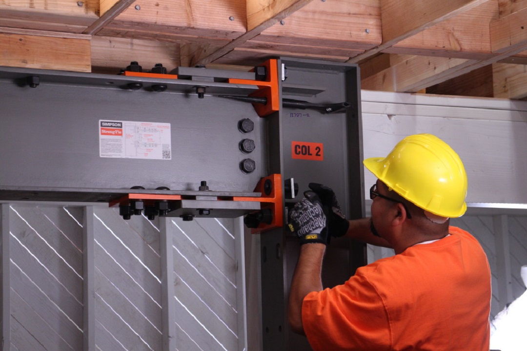
Another key advantage of the Simpson Strong-Tie special moment frame is no field welding is required, which eliminates the risk of fire in San Francisco’s older wood-framed buildings.
To learn more about San Francisco’s retrofit ordinance, watch a new video posted on strongtie.com/softstory. For more information about the Strong Frame special moment frame, visit strongtie.com/strongframe.

Remembering Barclay Simpson
On Saturday evening, Barclay Simpson passed away peacefully in his sleep, surrounded by his family. He was 93 years old. With Barc’s passing, Simpson Strong-Tie has lost a beloved and inspirational leader. Our country has lost a generous philanthropist, visionary and great American entrepreneur. Those of us who were fortunate enough to know and work with Barc have lost a dear friend, champion and guide.
Barc’s contributions to the construction industry, non-profit community and our employees are immeasurable. He instilled the core values — our “Secret Sauce” — that have made Simpson Strong-Tie a unique and inspiring place to work and have built our reputation as a quality, trusted manufacturer and solid corporate citizen.

The first time I met Barc was less than a week after I started working in the R&D department. I was meeting with a product manager and Barc was walking by, so he stopped in to say hello. We introduced ourselves and chatted for a few minutes. I told him about my work experience, where I went to school, what I was working on, and he even asked where I grew up. He was genuinely interested in getting to know me, which made me feel welcome.
I later noticed that Barc usually parked at the end of the building furthest from his office. He would take a different path through the building – sometimes through engineering, other times he would walk through marketing, accounting, or even the connector test lab. Barc cared deeply for all of his employees, and the intentionally long walk gave him the opportunity to talk with folks.
He firmly believed that everybody in the company is important, and he took every opportunity to remind us. In the video, Barclay Simpson’s Nine Principles of Doing Business, Barc speaks quite passionately about dignifying the contribution of every individual at every level.
In the end of a previous blog post, I mentioned Barc’s 1974 list of Rambling Thoughts on Making One’s Fleeting Moment on This Planet a Pleasant One. In the context of that post, the thoughts of “Attitude Conquers All” and “Keep it light. It really isn’t that important” were appropriate.
Thinking of Barc and his legacy, I prefer this rambling thought from his list:
Strive to have a POSITIVE EFFECT upon those lives touched by your own.

Our Latest Online Resource: Steel Deck Diaphragm Calculator
Although Simpson Strong-Tie is best known for our structural products: engineered structural connectors, lateral systems, fasteners and fastening systems, anchoring products and most recently, concrete repair, protection and strengthening (RPS) systems, we are continually developing new and exciting software solutions. As we’ve discussed in prior blog posts, Simpson Strong-Tie has numerous software programs and web and mobile apps available for download or online use at www.strongtie.com/software. Today, I’d like to review our recently launched web app, the Steel Deck Diaphragm Calculator. The calculator is accessible from any web browser and doesn’t require downloading or installing special software.
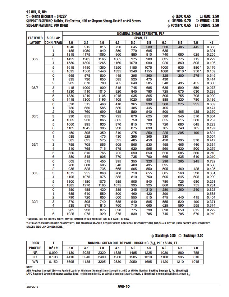
While the method of designing and specifying a steel deck and its attachment can vary by region, most designers are familiar with the Steel Deck Institute (SDI) and its Diaphragm Design Manual, 3rd Edition (DDM03). DDM03 presents diaphragm shear strength and stiffness equations for various steel deck profiles and commonly used attachment types (welds, power-actuated fasteners, or screws). The calculations can be quite tedious, so the SDI has developed numerous tables using these equations and placed them at the back of DDM03 for easy reference.
Since the tables in DDM03 are based solely on the fasteners and deck profiles included, determining diaphragm capacities utilizing any other proprietary fastener or deck profile fall on the designer or the proprietary product’s manufacturer. Enter Simpson Strong-Tie.
Our Steel Deck Diaphragm Calculator enables users to produce custom diaphragm tables similar to those in DDM03, generate detailed calculations using SDI equations based on project-specific inputs, as well as optimize deck fastening systems to ensure the most cost-effective design is utilized. The calculator incorporates our X-series steel decking screws, including the recently launched Strong-Drive® XL Large-Head Metal Screw, which has one of the highest capacities in the industry and in most cases, can be used as a 1-for-1 replacement of pins or 5/8 diameter puddle welds. (For additional information comparing Simpson Strong-Tie X-series and XL screws to pins or welds, review F-Q- STLDECK14.)

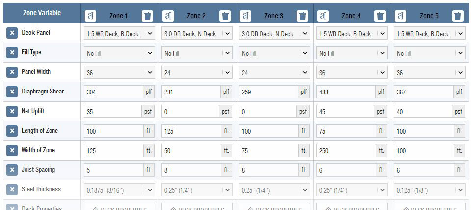
The app can be used with minimal required input to generate tables and project-specific calculations. A more detailed analysis can be performed by inputting parameters for up to five unique zones, including overall dimensions, diaphragm shear, joist spacing, uplift and more.
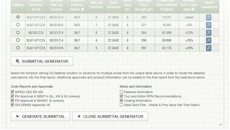
One unfortunate aspect of many web apps is that your work is typically lost once you close your web browser. I’m happy to report that the folks here in our app development group have added the ability to save and upload project files. The calculator also provides a clean PDF printout of your results while giving you the option to generate a submittal package with supporting documentation, such as code reports, product approvals and installation recommendations.
Try the revised Steel Deck Diaphragm Calculator yourself and let us know what you think. We always appreciate the feedback!

Meet Our Genuine Connector Campaign Grand Prize Winners
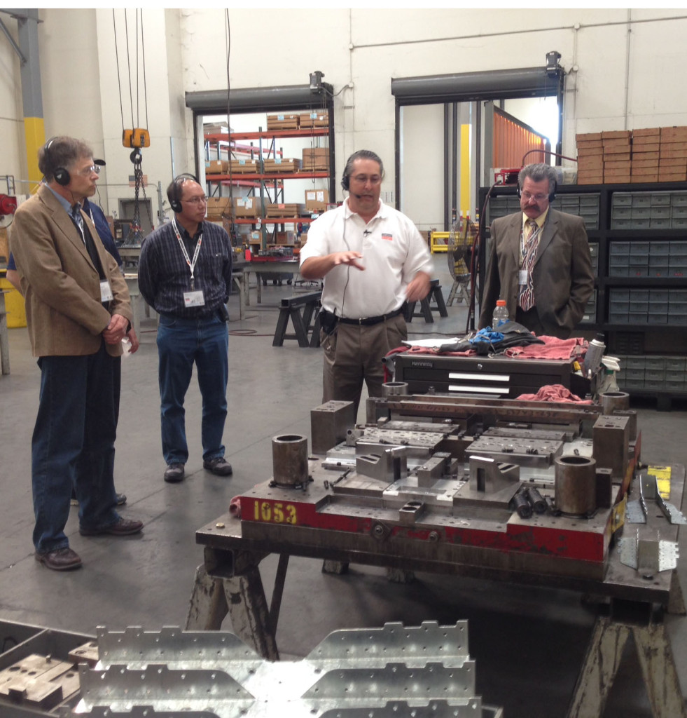
As part of our Genuine Connector Campaign, we had the pleasure of meeting with customers who won our Genuine Simpson Strong-Tie® Connectors contest. The grand prize was an all-expense paid trip to the San Francisco Bay area, and the opportunity to tour our state-of-the-art lab facilities as well as meet our senior managers. There were six winners; four visited us last October and we’re looking forward to meeting two more next month.
We launched a contest last year inviting customers to tell us their Genuine story. I shared mine in this blog post last January. As I mentioned in my previous post, our founder Barclay Simpson, made his very first connector for a customer in 1956. Barc believed in doing whatever it took to help the customer succeed. Today, helping the customer remains our number one priority. Whether that’s being on a jobsite to help with a product installation, making office calls to conduct product training or spending endless hours on R&D and product testing. This is what we promise to do everyday, and we do it genuinely.
But we wanted to know what it means to you. So we asked the question, “Why do you choose Genuine Simpson Strong-Tie® Connectors?”
We received many thoughtful, amazing responses. Honestly, it was hard to choose just six to receive our grand prize! Here are our the winning entries:
“It would be very easy for me to say that Simpson Strong-Tie Connectors are the only brand available in my area, which is true, but given a choice I would always select Simpson Strong-Tie. There are several reasons why I will always purchase Simpson Strong-Tie. First, I am quite impressed by Simpson Strong-Tie research and development to improve existing products and produce new ones. I have been fascinated by the extensive research facilities depicted in online videos. Especially, a video of the four- or five-story structure on the shake table for earthquakes. Your level of R&D tells me Simpson Strong-Tie backs everything they sell. Secondly, the quality of the products is impressive. The products are clean, without sharp edges or burrs from manufacturing processes, consistent in size and fit. Third, I appreciate the Simpson Strong-Tie commitment to meeting and exceeding building codes and keeping me up-to-date with specific applications. Lastly, I am impressed with Simpson Strong-Tie as a company: its people, leadership in its field and commitment to the building industry. Simpson Strong-Tie does not just talk about it. Simpson Strong-Tie does it.” P. Austin, North Adams, MA
“Think about what the world would be like without Genuine Simpson Strong-Tie® Connectors. In the Midwest, where recent storms have ravaged many communities, the losses would have been exponentially worse. The design and construction industries rely on this product line to make design and construction simpler using Simpson Strong-Tie. We take it for granted, I’m glad Simpson Strong-Tie doesn’t.” P. Lum, Florissant, MO
“Whether it is coated, stainless or composite, Simpson Strong-Tie is my connection. None of our projects are simple. Our strength, ingenuity and commitment require us to use the best of everything. Using Simpson Strong-Tie products means “never having to say you’re sorry.” The range of your products offer solutions to the many challenges we face. Many thanks to Barclay and his people for creating a company I can count on. It’s just that simple. I look forward to meeting your team someday. Many thanks, and keep up the good work!” T. Gould, Ashaway, RI
“My customers are looking for quality and innovation that they can count on. For years we have experienced that quality with Simpson Strong-Tie and continue to reap the benefits of products that save time and money and perform above expectations. The ability for Simpson Strong-Tie to build and ship custom products is second to none and often just what is needed to solve unexpected issues during the framing stage of our customers’ projects. Simpson Strong-Tie seems to always be ahead of code changes and working to help our customers with compliance. There is no equal!” L. Holmes, Torrington, WY
“The reason I use Simpson Strong-Tie is that they have the BEST customer service of any vendor that I have ever used. ANYONE that you get on the phone has the answer NOW on pricing, availability and any technical questions. The shipments are ALWAYS on time and in my 15 years, I have never seen a mistake. I deal with a lot of vendors and no one holds a candle to the service that Simpson Strong-Tie provides.” M. Stroupe, West Hartford, CT
“I have four reasons why I choose Genuine Simpson Strong-Tie Connectors. You can see them here in this picture. From left to right, they are Lilah, Callie, Hollie (being held), and Seth. Their safety is worth specifying connectors I can trust.” P. Giessel, Eagle River, AK
The contest may be over, but we’re still interested in your answer to the question: “Why do you choose Genuine Simpson Strong-Tie® Connectors?”

Genuine Connector Collection Art
In this earlier post, I shared the story of my brother-in-law indicating that he thought some of the connectors specified on a swim club project were “ugly.” The contractor and I were able to come up with some other options, but I guess I’m still upset with my brother-in-law for calling Simpson Strong-Tie® connectors ugly. I’ll have to walk into his office sometime and comment on the attractiveness of his financial audits. How pretty are those nonrecurring charges, unrealized capital gains and special purpose entities?Continue Reading

How to Safely Select Nail Substitutions for Connectors
A few days ago, I was speaking to a customer about an application using nail substitutions for a joist hanger installation. Her questions come up often, so I thought I would dedicate a blog post to some of the resources available that cover the use of different nails in connectors.
Designers and builders often wish to use different fasteners than the catalog specifies. The application could require short nails that don’t penetrate through the back of a ledger or they want to use screws or sinker nails for easier installation. The Wood Connectors Catalog provides multiple options for alternate nailing for face mount hangers and straight straps on page 24.

The load adjustments for alternate fasteners cover substitutions from a common diameter of 16d to a 10d, or a 10d to an 8d. Multiple different replacement lengths are also covered, with reduction factors ranging from 0.64 to 1.0.
It is important to remember that double shear hangers require 3” minimum joist nails. Short nails installed at an angle in double shear hangers will not have adequate penetration into the header.

Pneumatic nail guns used for connector installation are commonly referred to as positive placement nail guns. These tools either have a nose piece that locates connector hole, or the nail itself protrudes from the tool so that the installer can line the nail up with the hole. Most positive placement tools do not accept nails longer than 2½”, so framers using these tools will want to use 1½” or 2½” nails. To accommodate installers using pneumatic nails, we have a technical bulletin T-PNUEMATIC. This bulletin provides adjustment factors for many of our most common embedded holdowns, post caps and bases, hangers and twist straps.
The question of nail size also comes up when attaching hangers to rim board, which can range from 1” to 1¾”. The adjustment factors in C-2013 don’t necessarily apply with rim board, since the material may be thinner the length of the nails used. We also have a technical bulletin for that application – T-RIMBDHGR.
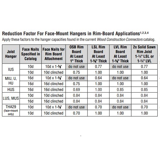
Several of the reduction factors are the same as those in the catalog. Testing of hangers with 10dx1½ nails on 1” OSB or 1¼” LVL did not do as well, however. We observed that once the nails withdrew a little bit under load, they quickly lost capacity. For that reason, we recommend full length 10d or 16d nails on those materials.
Understanding that alternate fasteners are available for many connectors can help you pick the right fastener for you application. When you specify a connector, it is important to also specify the fasteners you require to achieve your design load.
What are your thoughts? Visit the blog and leave a comment!