Simpson Strong-Tie® Research and Testing Lab Grand Opening, WSU Pullman

On Thursday, May 5, 2016, Washington State University at Pullman, state dignitaries, construction leaders, WSU construction alumni, PACCAR management, Simpson Strong-Tie management and the press celebrated the grand opening and dedication of the PACCAR Environmental Technology Building (PETB) and the Simpson Strong-Tie Research and Testing Laboratory.

pullman1

The Simpson Strong-Tie team comprised senior leadership, engineering and marketing representatives, led by our CEO, Karen Colonias. In her speech at the opening ceremony, Karen Colonias highlighted the leadership of Simpson Strong-Tie in the engineering and construction materials industry in the U.S. and the world. She emphasized the longstanding partnership between WSU and Simpson Strong-Tie, which spans over twenty years of collaboration in various testing and code development programs, and communicated our excitement at the opportunity to collaborate more closely with WSU’s highly respected engineering department on testing and engineering programs.

Karen Colonias speaking at the Grand Opening

The Paccar Environmental Technology Building (PETB) is 96,000 square feet and houses the Composite Materials and Engineering Center (CMEC) – a highly integrated hub of interdisciplinary research and education in the areas of renewable materials, sustainable design, water quality, and atmospheric research. The shared space in this new building will foster the synergy needed to find new solutions to complex industry problems, such as creating human environments that are at once safe, economical and resilient.

pullman3

The Simpson Strong-Tie® Research and Testing Lab at Washington State University (WSU) is a versatile laboratory designed specifically for the structural testing and prototyping of tall timber buildings, post frame buildings, concrete durability, building repair and retrofit and deck safety, as well as seismic and wind mitigation.

The lab includes a high-capacity reaction 28′ x 46′ concrete floor area with tie-downs, 75-kip capacity at two foot centers through the floor area; a high-capacity wall 28′ long by 2’thick by 18′ tall strong wall that is capable of withstanding a 200-kip reaction in any direction; a central 90-gallon-per-minute hydraulic pump, overhead crate and concrete mixing station. The laboratory is a dynamic space to test new material and design concepts developed in the PETB. This is one of the most visible spaces in the PETB and includes capabilities for mock-ups of new building systems, structural testing and advanced digital manufacturing. Adjoining the lab is an outdoor 32′ by 52′ reaction slab that allows for project display (e.g., Solar Decathlon competition), for developing taller and or larger structures than would be possible on the interior strong floor and for natural weather exposure testing.

pullman4

The lab is part of the Composite Materials and Engineering Center (CMEC), which has been a leader in the development of wood composite materials for more than 65 years. It is an International Code Council–accredited testing facility. The laboratory highlights engineered wood composites and is constructed of cross-laminated timber, glulam, Parallam and, of course, Simpson Strong-Tie® No- Equal connectors.

pullman5

Simpson Strong-Tie and WSU, as Karen Colonias mentioned in her speech, have a longstanding and productive partnership going back over 20 years. The two institutions have worked together in a number of areas, including new product testing, deck safety and seismic risk mitigation.

This year, Simpson Strong-Tie made a significant commitment and established the Simpson Strong-Tie Excellence Fund at the Voiland College of Engineering and Architecture at Washington State University (WSU). The fund provides an annual gift of $100,000 per year over the next eight years to support the new Simpson Strong-Tie® Research and Testing Lab in the PACCAR Environmental Technology Building (PETB). In addition to the lab, the Excellence Fund will support fellowships for professors and graduate students to present research findings, brainstorm about future research and conduct continuing education training.

The faculty of the Composite Materials and Engineering Center is committed to addressing the challenge of restoring and improving the U.S. civil infrastructure and offering an integrated approach linking material discovery, manufacturing innovation, product development, and customized design methodologies that will lead to high-performing, cost-effective solutions for the built environment. The core faculty possess diverse expertise that spans materials science (polymers, wood, cement, steel), durability and corrosion protection, manufacturing and sustainable design. The faculty also has a long history of involvement in developing building codes, standards and product acceptance criteria.

This year, the WSU Voiland College of Engineering and Architecture has more than 1,050 students enrolled in civil engineering, architecture and construction management programs. The alumni from these programs are founders of and senior executives in America’s top construction and design firms. The Wall Street Journal ranked WSU among the 25 universities whose graduates are top-rated by industry recruiters, and the Civil Engineering program is the 13th largest in the nation.

On October 29, 2016, and in line with this partnership, Simpson Strong-Tie is conducting its first annual engineering symposium at Washington State University Pullman. In this symposium, Simpson Strong-Tie engineers will share with the engineering and construction management students the various career opportunities that are available in the industry upon their graduation and introduce them to the exciting history of research and innovation at Simpson Strong-Tie. The Symposium will also include testing in the new lab of our No-Equal structural connectors and solutions.

At Simpson Strong-Tie, we are excited to be strengthening the partnership and increasing the collaboration with WSU faculty and students. We are looking forward to an extended and outstanding relationship that drives research and innovations and introduces new methods to design and construct safer, more resilient, sustainable and economical structures.

Onward and Upward!

Louay Shamroukh, P.E., S.E.

Engineering Manager, Northwestern U.S.

Simpson Strong-Tie® Strong-Wall® Wood Shearwall – The Latest in Our Prefabricated Shearwall Panel Line Part 2

In last week’s blog post, we introduced the Simpson Strong-Tie® Strong-Wall® Wood Shearwall. Let’s now take a step back and understand how we evaluate a prefabricated shear panel to begin with.

First, we start with the International Building Code (IBC) or applicable state or regional building code. We would be directed to ASCE7 to determine wind and seismic design requirements as applicable. In particular, this would entail determination of the seismic design coefficients, including the response modification factor, R, overstrength factor, Ωo, and deflection amplification factor, Cd, for the applicable seismic-force-resisting system. Then back to the IBC for the applicable building material: Chapter 23 covers Wood. Here, we would be referred to AWC’s Special Design Provisions for Wind and Seismic (SDPWS) if we’re designing a lateral-force-resisting system to resist wind and seismic forces using traditional site-built methods.Continue Reading

Hurricane Strong

This week will see the ultimate combination of events intended to raise public awareness of the necessity for disaster-resistant construction: It is week three of ICC’s Building Safety Month; National Hurricane Preparedness Week, as proclaimed by the U.S. president; the  NOAA Hurricane Awareness Tour of the Gulf Coast; and the kickoff of the new HurricaneStrong program.

hurricanestrong1

The ICC says that “Building Safety Month is a public awareness campaign to help individuals, families and businesses understand what it takes to create safe and sustainable structures. The campaign reinforces the need for adoption of modern, model building codes, a strong and efficient system of code enforcement and a well-trained, professional workforce to maintain the system.” Building Safety Month has a different focus each week for four weeks.  Week One is “Building Solutions for All Ages.”  Week Two is “The Science Behind the Codes.”  Week Three is “Learn from the Past, Build for Tomorrow.” Finally, Week Four is “Building Codes, A Smart Investment.” Simpson Strong-Tie is proud to be a major sponsor of Week Three of Building Safety Month.

hurricanestrong2

National Hurricane Preparedness Week is recognized each year to raise awareness of the threat posed to Americans by hurricanes. A Presidential Proclamation urged Americans to visit www.Ready.gov and www.Hurricanes.gov/prepare to learn ways to prepare for dangerous hurricanes before they strike. Each day of the week has a different theme. The themes are:
⦁ Determine your risk; develop an evacuation plan
⦁ Secure an insurance check-up; assemble disaster supplies
⦁ Strengthen your home
⦁ Identify your trusted sources of information for a hurricane event
⦁ Complete your written hurricane plan.

hurricanestrong3

hurricanestrong4

This week also marks the NOAA Hurricane Awareness Tour, where NOAA hurricane experts will fly with two of their hurricane research aircraft to five Gulf Coast Cities. Members of the public are invited to come tour the planes and meet the Hurricane Center staff along with representatives of partner agencies. The goal of the tour is to raise awareness about the importance of preparing for the upcoming hurricane season. The aircraft on the tour are an Air Force WC-130J and a NOAA G-IV. These “hurricane hunters” are flown in and around hurricanes to gather data that aids in forecasting the future of the storm. As with Hurricane Preparedness Week, each day of the tour features a different theme.  Simpson Strong-Tie is pleased to be a sponsor for Thursday, when the theme is Strengthen Your Home.  Representatives from Simpson Strong-Tie will be attending the event on Thursday to help educate homeowners on ways to make their homes safer.

hurricanestrong5

hurricanestrong6

Finally, this week is the official kickoff of a new hurricane resilience initiative, HurricaneStrong. Organized by FLASH, the Federal Alliance for Safe Homes and in partnership with FEMA, NOAA and other partners, the program aims to increase safety and reduce economic losses through collaboration with the most recognized public and private organizations in the disaster safety movement. HurricaneStrong is intended to become an annual effort, with activities starting prior to hurricane season and continuing through the end of the hurricane season on November 30. To learn more, visit www.hurricanestrong.org.


Experts consider these public education efforts to be more important every year, as it becomes longer since landfall of a major hurricane and as more and more people move to coastal areas. The public complacency bred from a lull in major storms has even been given a name: Hurricane Amnesia.


All these efforts may be coming at a good time, assuming one of the hurricane season forecasts is correct. A forecast from North Carolina State predicts an above-average Atlantic Basin hurricane season. On the other hand, forecasters at the Department of Atmospheric Science at Colorado State University are predicting an approximately average year.


Are you prepared for the natural hazards to which your geographic area is vulnerable? If not, do you know where to get the information you need?


Simpson Strong-Tie® Strong-Wall® Wood Shearwall – The Latest in Our Prefabricated Shearwall Panel Line Part 1

Some contractors and framers have large hands, which can pose a challenge for them when they’re trying to install the holdown nuts used to attach our Strong-Wall® SB (SWSB) Shearwall product to the foundation. Couple that challenge with the fact that anchorage attachment can only be achieved from the edges of the SWSB panel, and variable site-built framing conditions can limit access depending upon the installation sequence. To alleviate anchorage accessibility issues, we’ve required a gap between the existing adjacent framing and SWSB panel equal to the width of a 2x stud to provide access so the holdown nut can be tightened. Even so, try telling a framer an inch and a half is plenty of room in which to install the nut!Continue Reading

Habitat STRONG Blog

This week’s post was written by Kevin Gobble of Habitat for Humanity. Kevin is the Program Manager for Habitat for Humanity’s new Habitat Strong initiative. Kevin has spent over 22 years in residential construction building energy-efficient, high-performing home, and has consulted with several sustainable building programs on ways to develop their own best practices. As a third-generation builder, he has knowledge in the field of residential building science and has furthered his education to include many industry certifications — NARI Certified Remodeler, NAHB Certified Green Professional, RESNET Certified Green Rater, BPI Building Analyst, FORTIFIED evaluator, and Level 1 Infrared Thermography — while working directly with industry partners to focus on cost-effective construction solutions. Kevin has built and remodeled numerous homes to high-performance standards as certified by various building programs, including his latest project for himself: converting a condemned historic property in Atlanta to EarthCraft House Platinum.

In a previous blog post, we discussed the background of the Habitat Strong program. Habitat Strong promotes the building of resilient homes that are better equipped to withstand natural disasters in every region of the country. This program uses IBHS FORTIFIED Home™ standards and works well within Habitat’s model of building affordable, volunteer-friendly homes.Continue Reading

Multi-Ply Beam Load Transfer

Larger beams are often built up out of smaller 2x or 1¾” members. This can be done for several different reasons: for the convenience of handling smaller members on the jobsite, or because solid 4x, 6x or glulam material is not readily available, or for reasons of cost. Engineered wood such as laminated veneer lumber (LVL) is often used for its high load capacity and multiple 1¾” plies are built up to get the required capacity for the application.

8-Ply LVL Beam in HHGU14 Test

When a built-up beam is loaded concentrically as in the test setup shown, fastening the members is not critical since that giant steel plate will load each ply of the beam. In the field, built-up beams or girders commonly support joists or beams framing into their side. The built-up members must be connected to transfer load from the loaded ply into the other plies.

SDW - Uniform Allowable Loads
Allowable Uniform Loads and Spacing Requirements

SDW - Assembly Types and Spacing Requirements

Page 303 of our Fastening Systems catalog, C-F-14 provides allowable uniform load tables for side-loaded multi-ply assemblies using LVL, PSL or LSL material. The calculation for the allowable load applied to the outside ply of a multi-ply beam is:

Screen Shot 2016-04-28 at 2.07.29 PM

While uniform loads are very common, Designers often request additional information to design multi-ply beam connections to transfer concentrated loads. Simpson Strong-Tie has created a new engineering letter, L-F-SDWMLTPLY16, which complements the information in the Fastening Systems catalog by providing allowable loads in a single fastener format. Designers can use the information to calculate the number of fasteners required for a given point load.

Simpson Strong-Tie® Strong-Drive® SDW EWP-Ply Screw – Allowable Loads for Side-Loaded Multi-Ply Assemblies per Screw

In order to ensure load transfer, the SDW screws need to be located relatively close to the connection. At first glance, it may appear challenging to fit enough fasteners while meeting the non-staggered row-spacing requirements. However, we have found that most loads can be managed by taking advantage of the ⅝” stagger allowance.

SDW – Maximum Fastener Spacing from Point Load

If you are curious what happened in that HHGU14 test, the screws pulled out of the header with a load slightly exceeding 101,000 pounds. Failure photo 2 shows a close-up of the pullout failure. The tested load was very close to the maximum calculated capacity for the SDS screws in the connector, so it was a great test result. What are your thoughts? Let us know in the comments below.

HHGU14 Test Failure 1 HHGU14 Test Failure 2

Get There Quicker! How CFS Designer Can Help Speed Up Your Design Process

Did you know that Simpson Strong-Tie is celebrating its 60th birthday this year? We started out with one punch press and the ability to bend light-gauge steel. Then, one Sunday evening in the summer of 1956, Barclay Simpson’s doorbell rang and a request for our first joist hanger led us into the wood connector business. Since then, we’ve continued to grow that business by focusing on our engineering, research and development efforts. Some might say that nowadays we’re an engineering company that also happens to manufacture products, as evidenced by our focus on developing technology tools over the past few years such as web calculators, an updated website and design software. Our focus on technology, however, is really another aspect of our continued commitment to excellence in manufacturing and our application of the tenets of lean manufacturing.

Many of you may already be familiar with the idea of lean manufacturing made famous by Toyota in the early 2000s, along with the principles of continual improvement and respect for people. The concept of continual improvement is based on the idea that you can always make small changes to improve your processes and products. Although they were established in a manufacturing setting, these ideals ring very true for engineering as well; eliminate steps in your design process that don’t add any value to the final project and always be on the lookout for tools or techniques that can speed up your process. Thinking lean isn’t about cutting corners to get your result faster, it’s about mindfully getting rid of the steps that aren’t helping you and finding better ways of doing everyday tasks.

As structural engineers, we can find ourselves working on a variety of projects that lead us to perform repetitive calculations to check different conditions, such as varying parapet heights on the exterior of a building, or we may find ourselves working with an unfamiliar material, such as light-gauge or cold-formed steel (CFS), where we have to take some time away from design to review reference materials such as AISI S200-12 North American Standard for Cold-Formed Steel Framing. Wouldn’t it be great if there were a design tool that could help you complete your light-gauge projects more quickly, in complete compliance with current building codes?

It turns out that Simpson Strong-Tie offers a design tool called CFS Designer™ to help structural engineers improve their project design flow. This program gives engineers the ability to design light-gauge stud and track members with complex beam loading and span conditions according to building code specifications. What does that actually mean, though? Allow me to illustrate with an example of a design project.

Let’s say you’re designing a building and part of your scope is the exterior wall framing, or “skin” of the building. You probably get sent some architectural plans that look something like this:

Figure 1. Sample building elevation with section marks.

The architectural elevations will have wall section marks indicated for different framing situations. Two sample wall sections are shown in Figure 2.

Figure 2. Sample building wall sections.

This building has several different wall section types that include door and window locations, varying parapet heights, diverse finish materials that need to meet different deflection criteria, and different connection points back to the base building. The traditional design calculation that you would need to run for one wall section might begin with a loading diagram similar to Figure 3 below.

Figure 3. Sample calculation of wall stud loading diagram.

Once you have your loading diagram generated, you would need to use reference load tables or a computer analysis program to solve for the axial and moment demands, the reactions at the pinned supports, and the member deflections. 

After you determine the demand loads, you would then need to select a CFS member with sufficient properties, and you may need to iterate a few times to find a solution that meets the load and deflection parameters. After you’ve selected a member with the right width, gauge and steel strength, you’ll need to select an angle clip that can handle the demand loads, as well as fasteners to connect the clip to the CFS stud and to the base building. You would also need to also check the member design to ensure that it complies with bridging or bracing requirements per AISI. Then, after all that, you’d have to repeat the process again for all of the wall section types for your project.

Figure 4. Hmm, CFS design would sure be a lot easier if buildings were just huge windowless boxes…

Just writing out that whole process took some time, and you can imagine that actually running the calculations takes quite a bit longer. I think we can all agree that the design process we’ve outlined is time-consuming, and here’s where using CFS Designer™ to streamline your design process can really help.

CFS Designer is a structural engineering design program that can automate many of the manual steps that are required in the design process. It has an easy-to-understand graphical user interface that allows you to input your project parameters within a variety of design modules from walls and beams, jambs and headers, X-brace walls, shearwalls, floor joists, and roof rafters. The program also enables the design of single stud or track members, built-up box-sections, back-to-back sections, and nested stud or track sections. Figure 5 shows an example of how you would input the same stud we looked at before into the program.

Figure 5. CFS Designer™ user interface for wall stud design.

The program will generate the loading diagrams and complete calculation package for all of these different situations. And along with checking the member properties and deflection limits, CFS Designer will also check bridging and bracing requirements and provide connector solutions for the studs using tested and code-listed Simpson Strong-Tie products. Figure 6 shows an example of the summary output you would receive.

Figure 6. The comprehensive summary output page that covers the complete member design down to the bracing and connection solutions.

One unique part of the output is toward the center of the second page, under the heading “Simpson Strong-Tie Connectors.” This section summarizes the tension and compression loads at each reaction point and then shows a connector solution (such as the SCB45.5) along with the number of screws to the stud and the number of #12 sheet-metal screws to anchor back to the base building. Simpson Strong-Tie has developed and tested a full array of connectors specifically for CFS curtain-wall construction as well as for interior tenant improvement framing, which allows designers to select a connection clip straight out of a catalog without needing to calculate their own designs per the code. It’s just another way we’re helping you to get a little leaner!

speed7

Figure 7. A typical SCB/MSCB bypass framing slide-clip connector showing directional loading along with the table of allowable connector loads.

The last part of the output shown in Figure 6 is titled “Simpson Strong-Tie Wall Stud Bridging Connectors.” It checks the bridging and bracing requirements per AISI S100 and selects a SUBH bridging connector, an innovative bridging solution developed by Simpson Strong-Tie that snaps into place and achieves design loads while only requiring one #10 screw to connect for 75% of applications.

Figure 8. A close-up of the SUBH installed (left) and a wall of studs with bridging installed using the LSUBH clips (right).

You can download a free trial of CFS Designer™ and give it a test drive to see how much time it can save you on a design project. The trial version has almost full functionality, with the exception of not being able to print the output sheets. You can see purchasing information online, and you should always feel free to contact your local Simpson Strong-Tie engineering department with any questions you may have. I hope you are able to take advantage of this great tool to further improve your everyday design processes. We will be sure to keep you updated on our latest technology tools that help speed up the design process.  If you’re using CFS Designer, we’d like to hear your thoughts about the program. Please share them in the comments below.


Fine Homebuilding Video Series: How to Build a Deck

We’re partnering with folks at Fine Homebuilding on a video series on how to build a deck that is code compliant and that highlights the critical connections of a deck. This series is called Ultimate Deck Build 2016. The video series comprises five videos that walk professionals through the recent code changes for the key connections of a deck.

The series features David Finkenbinder, P.E., a branch engineer for Simpson Strong-Tie who is passionate about deck codes and safety. He offers information on load resistance and the hardware that professionals can use at the crucial connections to make a deck code compliant. “This was a great opportunity to collaborate with the team at Fine Homebuilding, to communicate the connections on a typical residential deck and the role that they serve to develop a strong deck structure,” said David. “These same connections would also likely be common in similar details created by an Engineer, when designing a deck per the International Building Code (IBC).”

Screen Shot 2016-03-30 at 3.49.17 PM

The videos are being released every Wednesday during the month of March and feature the following deck connections:

  • Ledger Connection: This is the primary connection between a deck and a house. David tells the Fine Homebuilding team about various code- compliant options for attaching a deck ledger to a home.
  • Beam and Support Posts: David explains how connectors at this critical point can prevent uplift and resist lateral and downward forces. He also discusses footing sizes and post-installation anchor solutions.
  • Joists: This video reviews proper joist hanger installation and the benefits of installing hurricane ties between the joists and the beams. David goes into common joist hanger misinstallations, such as using the wrong fasteners or using a joist hanger at the end of a ledger.
  • Guardrail Posts: David reviews the different ways that you can attach a guardrail post so as to resist an outward horizontal load.
  • Stairs: David explains code-compliant options for attaching stringers to a deck frame.

Make sure to watch the series and let us know what you think. For more information, Fine Homebuilding has created an article titled “Critical Deck Connections.”

(Please note: this article is member-only/subscription content, so to read it you’ll need to either subscribe online or pick up the April/May issue of Fine Homebuilding.)

Screen Shot 2016-03-30 at 4.06.33 PM

Corrosion Resistance Classification

This week we’re blogging about corrosion, and we’re not talking about rusting of the soul — we’re talking about oxidation of steel.

In 2014, we reviewed our corrosion protection recommendations for new catalog publications. In doing so, we realized that we could facilitate selection of hardware and fasteners if our Corrosion Resistance Classifications for treated wood were linked to common design conditions described in the codes. We made some revisions to our Corrosion Resistance Classifications during that exercise. This blog post talks about those changes and some current related activity in the wood treatment industry.

The common design conditions for corrosion-resistant wood construction include the wood materials with associated treatments and the environmental corrosion agents. The American Wood Protection Association (AWPA), which is an ANSI-accredited consensus standards organization, publishes the code-referenced standard, AWPA U1-15 Use Category System: User Specifications for Treated Wood.

When you specify treated wood, this is the standard that defines the appropriate treatment chemicals and chemical retentions depending on the exposure condition and bio-hazard, which the AWPA has summarized into a Use Category (UC) system. Figure 1 is a clip from the AWPA web site that gives a glimpse at the UC system. As the UC rating increases from UC1 to UC5, the chemical retention increases because the bio-hazard is increasing. Corrosion hazards are directly related to the combination of treatment chemical, treatment chemical retention and use environment.

Figure 1. Summary of AWPA Use Category System (http://www.awpa.com/standards/U1excerpt.pdf)
Figure 1. Summary of AWPA Use Category System http://www.awpa.com/standards/U1excerpt.pdf

The AWPA UC system does not include environmental corrosion agents. As a result, we had to separately integrate those with treatment chemical effects as we developed the corrosion resistance classifications.

Finally, one more evaluation system had to be addressed: the exposure conditions of ICC-ES AC257 — Corrosion Resistant Fasteners and Evaluation of Corrosion Effects of Wood Treatment Chemicals. In the end, we developed Corrosion Resistance Classifications that considered the AWPA Use Categories, environmental corrosion agents and the ICC-ES AC257 exposure conditions.

Some of you may be thinking that we have not mentioned another aspect of corrosion — galvanic corrosion. Galvanic corrosion results when metals with dissimilar electrical potentials are placed in contact in the presence of an electrolyte (water). We’ll take up galvanic corrosion in a subsequent blog post.

Our basic Corrosion Resistance Classification table is shown in Figure 2.

Figure 2. Corrosion Resistance Classifications (from C-F-2014, p. 15, or strongtie.com)

The ratings shown in the table — Low, Medium, High and Severe — refer to the corrosion resistance of Simpson Strong-Tie coating systems and base metals. An example of a coating system that is rated “Low” is paint or electro-galvanized zinc. An example of a material rated for “Severe” corrosion conditions is Type 316 stainless steel.

To use the Corrosion Resistance Classifications table, find the Environment, then move to the correct column in the Material to Be Fastened section; identify a rating. Then look in the companion table labeled “Corrosion Resistance Recommendations” to identify a coating or base metal that is appropriate for your project. Be sure to read the table notes to the Corrosion Resistance Classifications for exceptions and limitations. We implemented this system to simplify product selection. Let’s take a look at each aspect that contributes to the Corrosion Resistance Classifications table.

Environment                                                                                      

The environment captures the moisture, atmospheric conditions and other elements that affect corrosion rate. “Dry Service” usually means an interior space with low moisture content or dampness. No liquid water is present in this sort of environment. The absence of moisture limits the electrochemical reaction needed to produce what we see as corrosion. “Wet Service” usually means exterior exposure and involves liquid water as direct exposure or condensation and wood moisture contents that can exceed air-dry conditions and may be temporary or persist for prolonged periods. We incorporated environmental agents with the “Elevated Service and Ocean/Waterfront” conditions. These environmental agents include fumes, acid rain, airborne salinity, etc. The “Uncertain Environment” was included for the Designer who does not know the corrosive conditions in service.

Material Being Fastened

Here we distinguish between clean materials and wood treated with chemicals — wood preservatives or fire-retardant chemicals (FRT). Untreated softwoods used for framing are generally not significantly corrosive. This does not include cedars and redwood, which are a special case. Cedars tend to be corrosive and particularly prone to staining when fastened with carbon steel hardware and fasteners. As a result, our recommendations for untreated softwoods are generally a function of the environment — moisture, weather exposure and corrosion agents such as salt spray, sulfur or fertilizer fumes and acid rain are all examples.

Some treatment chemicals do not significantly increase the corrosion hazard. These are the SBX-DOT treatment chemicals (inorganic boron and borate treatments). These are not typically used in exterior environments or for high-moisture conditions. The preservatives are not chemically bound to the wood and they can leach out under exposure to liquid moisture, which would leave the wood unprotected.  The corrosion hazard attendant to these chemicals is similar to that of untreated wood and the codes permit the use of bare carbon steel in contact with wood treated with these chemicals (IBC2015, Section 2304.10.5.1 and IRC2015, Section R317.3.1 (exception 3)).

Most of the waterborne chemicals in common use contribute to an elevated corrosion hazard. Some of the common wood treatment chemicals include formulations of alkaline copper quaternary (ACQ), copper azole (CA), ammoniacal copper zinc arsenate (ACZA) and micronized copper azole (MCA). The AWPA UC system defines the exposure conditions for each Use Category as well as the chemical retention required to prevent a decay failure. The MCA formulations are alternatives to those specified in the code-referenced standard through the evaluation report process and are not standardized by the AWPA. The evaluation report process for wood preservatives requires the submission of evidence in compliance with ICC-ES AC326 — Proprietary Wood Preservative Systems Common Requirements for Treatment Process, Test Methods and Performance.

We realize that UC4A is a general-use ground-contact condition, and further, it is the maximum necessary specification for treated wood in many building applications. The Simpson Strong-Tie Corrosion Resistance Classifications recognize that the corrosion hazard of treatment chemical retentions for UC4A in Wet Service is a “Medium” corrosion condition (with the exception of ACZA, which is rated “High” in Wet Service). This means that carbon steel products with sufficient corrosion resistance (e.g., ZMAX, double barrier coating, etc.) can be used in these conditions assuming no other corrosion-causing agents are present.

On the other hand, the moisture conditions and treatment chemical retentions are elevated in UC4B and UC4C, and there is also a potential for salt exposure, which further escalates the corrosion hazard. In these conditions, stainless steel is generally recommended for connectors and fasteners as the best material for mitigating the corrosion risk.

The last column in the Corrosion Resistance Classifications table is devoted to FRT wood. Fire-retardant treatment chemicals are proprietary and are deemed to meet the requirements of the codes through the evaluation report process (ICC-ES AC66 — Acceptance Criteria for Fire-Retardant-Treated Wood). We cannot evaluate the corrosion resistance of hardware to all of the FRT formulations.  However, we have reviewed most of the FRT evaluation reports for corrosion information. The corrosion effects of FRT chemicals, like preservative treatment chemicals, are minimized in dry-service conditions because the electrochemical reaction cannot progress or is slowed without an electrolyte. The Corrosion Resistance Classifications reflect that information. The Designer should always follow the FRT evaluation reports in addition to considering our recommendations.

It is important to note that the Corrosion Resistance Classifications are not associated with specific applications. Rather, the ratings are based on the integrated effects of the environment and the wood treatment where the chemical retentions given in the AWPA Use Category system play an important role in the ratings. This makes it relatively straightforward to select hardware that is adequate for a design environment.

Changes to the AWPA U1 Standard and Effects on Corrosion Resistance Classifications

As noted here and in the online JLC article, wood preservative chemicals can achieve compliance with the codes by either of two methods:

  1. The product is a generic product (e.g., ACQ-D or CA-B) and is listed in the AWPA U1 standard; or
  2. The product has an evaluation report obtained by submitting evidence in accordance with ICC-ES AC326 — Proprietary Wood Preservative Systems Common Requirements for Treatment Process, Test Methods and Performance.

You may be aware that the AWPA is revising its code-referenced standard, AWPA U1-15, Use Category System: User Specification for Treated Wood. The consensus process is ongoing and is not complete. However, AWPA member chemical companies (Viance, Koppers, and Arch) have placed information in the market.  In parallel with the AWPA, ICC-ES has modified AC326 to reflect the changes ongoing in the AWPA U1 standard. Simpson Strong-Tie has been in contact with the AWPA, other industry associations and industry professionals to understand the potential effects on metal hardware of the AWPA U1 and ICC-ES AC326 revisions.

The proposed revisions to the AWPA U1 standard modify the definitions for UC3A, UC3B, UC4A, UC4B and UC4C. The most important revisions are to UC3B and UC4A. The new definition for applications in UC3B suggests that beams and joists in decks and docks may have bio-hazards that exceed the UC3B assumptions, while the new UC4A definition will include above-ground applications with ground- contact hazards. The revised AWPA U1 standard will be published in the May–June 2016 time frame; AWPA U1-16 will be included in the 2018 codes.

The revision to ICC-ES AC326 also modifies the definitions for UC3B, UC4A and UC4B. ICC-ES AC326 has an implementation date of July 2016, which will cause some changes to specifications this summer.  Micronized copper azole (MCA) formulations are the most common treatment chemicals that will be affected by this action.

Revisions to the Use Category definitions are being driven by two issues:

  1. Wood treated for UC3 is sometimes used in near-ground applications where the bio-hazard is more like UC4.
  2. Under-treatment compromises the margin of safety to bio-hazards, which can lead to decay failures.

Rather than revisit the retention specifications in AWPA U1 standard, the AWPA is modifying the definitions for the Use Categories that are involved, and that language has been carried into ICC-ES AC326 to ensure that the two systems are consistent with each other. The result of changes to the Use Category definitions will likely cause some specifications to change from UC3B to UC4A or from UC4A to UC4B. The main effects will likely be to specifications in eastern and southern states, where there may be more chemical in the wood to meet retention specifications.

The Simpson Strong-Tie Corrosion Resistance Classifications make specific reference to the corrosive levels of environmental conditions and the chemical treatment and retentions of the AWPA Use Categories, not to applications. As a result, the AWPA U1 revisions and the parallel changes to ICC-ES AC326 will not necessitate a change in our corrosion recommendations, because the chemical retentions for each Use Category have not changed. However, your hardware specifications could change for typical applications depending on the Use Category of the treated wood in your project. Our information suggests that this issue is still not settled within the industry, and we will pass along information as we learn it.

Simpson Strong-Tie is currently preparing new catalogs for the coming year and will be updating the corrosion information in those publications and our website. We’re interested in your experience with our Corrosion Resistance Classifications and whether you have suggestions for how we might make the content more useful to you.

Introducing Our New Website

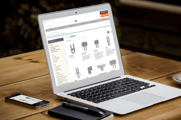
We know many of you visit our website on a regular basis for product and technical information and to use our software, calculator tools and other web apps. If you haven’t visited strongtie.com recently, it has a new look and several new features, including enhanced search and browsing and a mobile-friendly design. Here are some of the new features and site improvements:

  • Update-to-date product information: If there is a new code report, catalog or product you will be able to find that information on our new website first. It has the latest product and technical information while retaining the same features and information you expect.
  • Enhanced search and browsing: You can now search for our products based on specific product attributes. Our enhanced search capabilities allow you to explore our collection of products by applying filters so you can quickly and easily browse and find the products that you are looking for.
  • Mobile-friendly: Our new site has a responsive design that allows you to view the site in any format. From large desktops to mobile devices, you can view our site in the office or while on the go.
  • Enhanced Visuals: We have added new and improved photographs, illustrations and graphics so that you can see our products in greater detail.

We hope the new website better serves your design and technical needs. If you have any suggestions, comments or feedback, please email us at web@strongtie.com or leave a comment below.

str-eng-blog-new-site-v2