

Last week’s post reviewed some of the common questions WoodWorks receives from engineers designing five-story, Type III wood-frame buildings—including those related to fire retardant-treated building elements, and fire-rated floor and wall assemblies. This week, we extend that conversation to another common issue—details and fire rating of floor-to-wall intersections.Continue Reading
Category: Building Codes
It can be hard to keep up with or understand all of the building codes. That’s where Simpson Strong-Tie’s engineers coming in.
Fire Protection Considerations with Five-Story Wood-Frame Buildings Part 1
As a regional director for WoodWorks, my job is to provide technical assistance related to the design of nonresidential and multi-family wood buildings. I’ve been with the program since it launched in 2007 and, although we support a full range of building types, I’ve seen a steady increase in the number of design professionals looking for information and support related to mid-rise wood structures in particular.Continue Reading
Concrete Anchor Design for the International Building Code: Part 3
Specification of Concrete Anchors
The 2012 IBC and its Referenced Standard, ACI 318-11, is the first to mandate that contract documents specifically address installation, inspections and design parameters of concrete anchorage. For this reason, the specification of anchors in drawing details alone is impractical. To fully and effectively address these code mandates, concrete anchorage is more practically specified in both drawing detail(s) and the General
Structural Notes or specifications of the contract documents. The drawing detail(s) would typically call out the anchor type, material specification, diameter, and embedment depth. The General Structural Notes or specifications would include the name of the qualified anchor(s) and address the installation, inspections and design parameter requirements of ACI 318-11.
The following sections of ACI 318-11 discuss the contract document requirements for concrete anchorage:
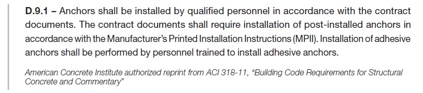
The commentary in ACI 318-11, RD.9.1 discusses the sensitivity of anchor performance to proper installation. It emphasizes the importance of qualified installers for all anchors, and compliance with the Manufacturer’s Printed Installation Instructions (MPII) for post-installed anchors. Training is required for adhesive anchor installers per ACI 318-11 D.9.1. Simpson Strong-Tie Co. Inc. provides free installer training by experienced Technical Sales Representatives for our adhesive, mechanical and specialty anchors. Contact us at 1-800-999-5099. Special inspection and proof loading are addressed in ACI 318-11 D.9.2
and D.9.2.1.
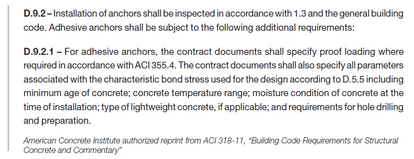
Per the section above, anchor installation requires inspection per Section D.9.2. In addition, the design parameters for adhesive anchors are required to be specified in the contract documents. An explanation of the design parameters listed in ACI 318-11 D.9.2.1 is provided below:
- Proof loading where required in accordance with ACI 355.4. Proof loading is only required for adhesive anchors loaded in tension in which the inspection level chosen for the adhesive anchor design is “Continuous” (Ref. ACI 355.4 Section 10.4.6). Selecting “Continuous Inspection” can result in a higher “Anchor Category,” which in turn results in a higher strength reduction factor, φ. Reference Section 13.3.4 of ACI 355.4 for the minimum requirements of the proof loading program, where required. The Design Professional is responsible for performing the quantity, the duration of
the applied load, and the proof load to which the anchors will be tested. These parameters will be specific to the anchor design conditions. - Minimum age of concrete at time of anchor installation. Per ACI 318 D.2.2, adhesive anchors must be installed in concrete having a minimum age of 21 days at time of anchor installation. Simpson Strong-Tie® has performed in-house testing of SET-XP®, AT-XP®, and ET-HP® adhesive anchors installed in 7-day- and 14-day-old concrete. The results of testing are published in an engineering letter (L-A-ADHGRNCON15.pdf), which can be viewed and downloaded at www.strongtie.com.
- Concrete temperature range. This is the in-service temperature of the concrete into which the adhesive anchor is installed. Temperature Ranges are categorized as 1, 2 or 3. Some manufacturers use A, B, or C as the category designations. Each Temperature Range category has a maximum short-term concrete temperature and a maximum long-term concrete temperature. Short-term concrete temperatures are those that occur over short intervals (diurnal cycling). Long-term concrete temperatures are constant temperatures over a significant time period.
- Moisture condition of concrete at time of installation. Moisture conditions, as designated by ACI 355.4, are “dry,” or “water-saturated.” Moisture condition impacts the characteristic bond stress of an adhesive.
- Type of lightweight concrete, if applicable.
- Requirements for hole drilling and preparation. These requirements are specific to the adhesive, and are described in the Manufacturer’s Printed Installation Instructions (MPII). Reference to the MPII in the contract documents is sufficient.
Adhesive anchors installed in a horizontal or upwardly inclined orientation that resist sustained tension loads require a “certified” installer.
A certification program has been established by ACI/CRSI. Installers can obtain certification by successful completion of this program. Contact your local ACI or CRSI chapter for more information. Other means of certification are permitted, and are the responsibility of the licensed design professional.
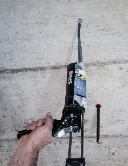
The installation of adhesive anchors in a horizontal or upwardly inclined orientation presents unique challenges to the installer. Simply put, the effects of gravity for these applications make it difficult to prevent air bubbles and voids, which can limit full adhesive coverage of the insert (threaded rod or reinforcing bar). Due to the increased installation difficulty of these anchors, they are required to be continuously inspected by a certified special inspector.
Suggested General Structural Notes or specifications for post-installed anchors can be viewed and downloaded at here, or contact a Simpson Strong-Tie® representative for help with your post-installed General Structural Notes or specifications.
Simpson Strong-Tie Suggested General Note for Anchor Products
Post-Installed Anchors into Concrete, Masonry and
Steel and Cast-in-Place Anchors into Concrete
The below products are the design basis for this project. Substitution requests for products other than those listed below may be submitted by the contractor to the Engineer-of-Record (EOR) for review. Substitutions will only be considered for products having a code Report recognizing the product for the appropriate application and project building code. Substitution requests shall include calculations that demonstrate the substituted product is capable of achieving the equivalent performance values of the
design basis product. Contractor shall contact manufacturer’s representative (800-999-5099) for product installation training and a letter shall be submitted to the EOR indicating training has taken place. Refer to the building code and/or evaluation report for special inspections and proof load requirements.
- For anchoring into cracked and uncracked concrete
a) Mechanical anchors shall have been tested in accordance with ACI 355.2 and/or ICC-ES AC193 for cracked concrete and seismic applications. Pre-approved products include:
i. Simpson Strong-Tie® Strong-Bolt® 2 (ICC-ES ESR-3037)
ii. Simpson Strong-Tie® Titen HD® (ICC-ES ESR-2713)
iii. Simpson Strong-Tie® Torq-Cut® (ICC-ES ESR-2705)
iv. Simpson Strong-Tie® Titen HD® Rod Hanger (ICC-ES ESR-2713)
v. Simpson Strong-Tie® Blue Banger Hanger® (ICC-ES ESR-3707, except roof deck insert)
b) Adhesive anchors shall have been tested in accordance with ACI 355.4 and/or ICC-ES
AC308 for cracked concrete and seismic applications. Adhesive anchors shall be installed
by a certified adhesive anchor installer where designated on the contract documents.
Pre-approved products include:
i. Simpson Strong-Tie® AT-XP® (IAPMO-UES ER-263)
ii. Simpson Strong-Tie® SET-XP® (ICC-ES ESR-2508)
III. Simpson Strong-Tie® ET-HP® (ICC-ES ESR-3372)
Concrete Anchor Design for the International Building Code: Part 2
Designing “Alternative Materials”
Concrete anchor types whose designs are not addressed in the IBC or its Referenced Standards, or are specifically excluded from the scope of the Referenced Standard (ACI 318-11), may be recognized as Alternative Materials. Section 1909 of the 2012 IBC requires that “The strength design of anchors that are not within the scope of Appendix D of ACI 318, shall be in accordance with an approved procedure.” Section D.2.2 of ACI 318-11 lists some concrete anchor types that are considered “Alternative Materials” and specifically excludes these anchors from its scope. The list of “Alternative Material” anchors provided in this section is not, however, a comprehensive list.
Section 104.11 of the 2012 IBC describes how the design professional must approach the design of Alternative Materials.
Section 104.11 provides the design professional with two options for the substantiation of the acceptable performance of an Alternative Material:
a. Research Reports. As described in the previous section (Design of Code Anchors), Research Reports are referenced as the primary source for the design and qualification of Alternative Materials. Research Reports for anchors are published by IAPMO UES or ICC-ES, both ANSI ISO 17065 accredited agencies. Publicly developed, majority-approved acceptance criteria are used to establish the test program and minimum performance requirements for an anchor type. Some Alternative Material anchor types have established acceptance criteria to which a product can be evaluated:
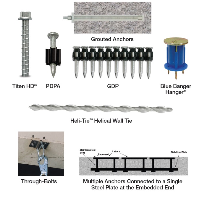
- Screw Anchors in Concrete (such as Simpson Strong-Tie® Titen HD®): ICC-ES AC193
- Headed Cast-in Specialty Inserts (such as Simpson Strong-Tie® Blue Banger Hanger®): ICC-ES AC446
- Powder- or Gas-Actuated Fasteners (such as Simpson Strong-Tie® PDPA and GDP): ICC-ES AC70
If Research Reports are used to substantiate an anchor’s performance, the design professional is bound by the design methodology and product limitations described in the Research Report.
b. Tests. If a Research Report is not available, and no acceptance criteria exists for a given anchor type, IBC Section 104.11 permits the use of tests performed in accordance with “recognized and accepted test methods” by an “approved agency” to substantiate performance. One example of an anchor type for which no acceptance criteria exists is:
- Helical Wall Ties (such as Simpson Strong-Tie® Heli-Tie™)
Cracked Concrete Determination
One of the many design considerations that the design professional must determine when designing either “Code Anchors” or anchors qualified as “Alternative Materials” is whether to consider the state of the concrete “cracked” or “uncracked.” The concrete state can significantly influence the anchor’s capacity. Neither the IBC nor ACI 318, Appendix D explicitly defines which applications should be categorized as “cracked” or “uncracked” concrete. The design professional must determine by analysis whether cracking will occur in the region of the concrete member where the anchors are installed. Absent an analysis to determine whether cracking will occur, the design professional may conservatively assume that the concrete state is “cracked.” With that said, there are two circumstances that require the design professional to design for “cracked” concrete:
a) Anchors in structures assigned to Seismic Design Categories C, D, E, or F (per 2012 IBC, Chapter 16) are required to be designed for “cracked” concrete unless the design professional can demonstrate that cracking does not occur at the anchor locations. The prequalification requirements of ACI 355.2 for mechanical anchors and ACI 355.4 for adhesive anchors include a test program that evaluates the performance of anchors in cracked concrete. Only anchors that have been tested and have passed the cracked concrete test program qualify for use in “cracked” concrete. The Research Report for a post-installed anchor (mechanical or adhesive) will clearly indicate whether it qualifies for use in “cracked concrete.”
b) Anchors located in a region of the concrete element where analysis indicates cracking at service level loading must be designed for “cracked” concrete (e.g. fr ≥ 7.5λ√f’c, ACI 318-11 eq. 9-10).
The design professional must consider additional factors that have the potential to result in concrete cracking in the region of anchorage. These factors include restrained shrinkage, temperature changes, soil pressure, and differential settlement. If no cracking is assumed in the region of the anchorage, the design professional should be able to justify that assumption.
Design Calculations
The design methodology in ACI 318 Appendix D is cumbersome. Calculations can be performed by hand using the design equations in Appendix D, inserting the substantiated data from an anchor manufacturer’s data tables or Research Reports to design with post-installed anchors. Designing with cast-in-place “Code Anchors” does not require additional data beyond what is included in ACI 318, Appendix D since these are “standard” anchors with standard design characteristics.
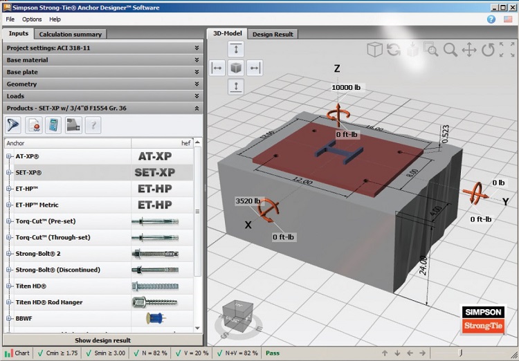
Performing hand calculations can be time-consuming, and for most design professionals is impractical due to the complexity of the design equations associated with multiple failure modes required to be considered. Design software, such as Simpson Strong-Tie® Anchor Designer™ Software for ACI 318, ETAG and CSA provides a fast, reliable method of calculating anchor performance for both cast-in-place and post-installed anchors. This software designs both “Code Anchors” and “Alternative Materials” for which an acceptance criteria exists.
Simpson Strong-Tie® Anchor Designer™ Software for ACI 318, ETAG and CSA is free and can be downloaded here.
Concrete Anchor Design for the International Building Code: Part 1
Purpose
The intent of this technical bulletin is to clarify code language and outline the correct path for the design of concrete anchors under the International Building Code (IBC). The reader will be able to clearly distinguish between “code anchors” and anchors that are considered “alternative materials,” as well as understand the logical sequence of code language for designing each type. The distinction between “cracked” concrete and “uncracked” concrete anchor design will be made. This technical bulletin will lend clarity to the qualification of post-installed anchors for use in concrete. Excerpts from the IBC and its Referenced Standards will be provided to facilitate the description of the design requirements.
Background
More than a decade after the introduction of the American Concrete Institute’s ACI 318, Appendix D design methodology for anchor design in 2002, many design professionals either do not fully understand or are unaware of the code requirements for the design of concrete anchors. Several factors contribute to the challenges associated with understanding the code mandates:
1. The incorrect notion that ACI 318, Appendix D is exclusively for anchors designed for “cracked concrete,” leading to regionally varying degrees of enforcement and implementation of the design requirements
2. Multiple Reference Standards for the design and qualification of different anchor types
3. The evolving scope of Reference Standards, which have reclassified some anchors as “Code Anchors” that were previously considered “Alternative Materials”
4. Confusing language in IBC sections that address concrete anchorage
5. Complexity of the anchor design methodology itself
6. Varying levels of special inspections enforcement
It is nevertheless incumbent upon the licensed design professional to design anchors in accordance with the minimum provisions of the code in order to protect public safety, reduce liability risk and fulfill professional responsibilities.
The International Building Code, beginning with the 2000 edition, describes the design methodology of concrete anchors by virtue of the language within the IBC itself, or through language in the Referenced Standard (ACI 318). In this technical bulletin, specific reference to the 2012 IBC and ACI 318-11 will be made, since this is currently the most widely adopted edition of the IBC.
“Code Anchors” and “Alternative Materials”
Anchors can be divided into two major categories: 1) “Code Anchors”, which are those that are specifically addressed in the IBC or its Referenced Standards, and 2) “Alternative Materials”, the design and qualification of which are not addressed in the IBC or its Referenced Standards.
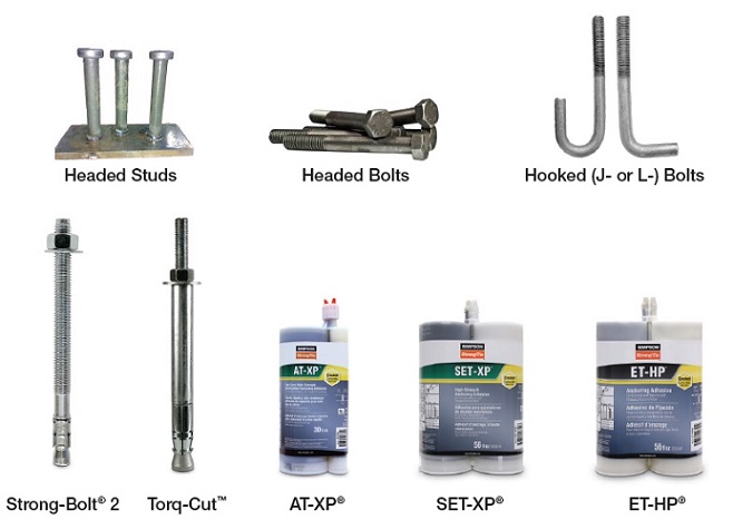
The following “Code Anchors” recognized by the 2012 IBC:
- Headed studs
- Headed bolts
- Hooked (J- or L-) bolts
- Expansion anchors(such as Simpson Strong-Tie® Strong-Bolt® 2)
- Undercut anchors (such as Simpson Strong-Tie® Torq-Cut™)
- Adhesive anchors (such as Simpson Strong-Tie® SET-XP®, AT-XP®, and ET-HP®)
Anchor types not listed above are considered “Alternative Materials.”
The following are anchors qualified as such:
- Screw anchors (such as Simpson Strong-Tie® Titen HD®)
Alternative materials also apply to anchor types specifically excluded from ACI 318-11 calculation and analysis requirements.
- Specialty inserts (such as Simpson Strong-Tie® Blue Banger Hanger®)
- Through-bolts
- Multiple anchors connected to a single steel plate at the embedded end
- Grouted anchors
- Powder- or gas-actuated fasteners (such as Simpson Strong-Tie® PDPA)
Designing “Code Anchors”
The starting point for the design of all anchors is Section 1908 of the 2012 IBC.
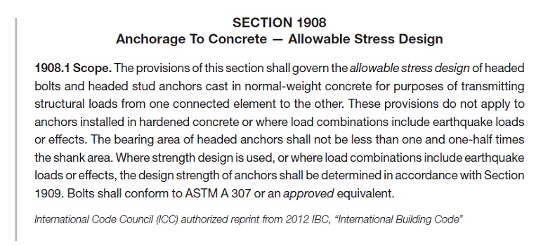
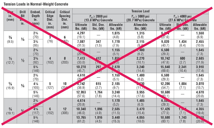
Section 1908.1 states that only cast-in-place headed bolts and headed studs are permitted to be designed using “Allowable Stress Design,” provided that they are not used to resist earthquake loads or effects. For these anchors, Section 1908.2 references Table 1908.2 for the determination of the allowable service load. Section 1908.1 makes explicit reference to post-installed anchors (anchors installed into hardened concrete), stating that the provisions of “Allowable Stress Design” is not permitted. For the design professional, this means that determining anchor by means of “Allowable Load Tables” based on previous test criteria that used a safety factor of 4.0 to determine allowable loads, as in the example below, is not permitted under the IBC.
Section 1909 of the 2012 IBC, “Anchorage to Concrete – Strength Design” makes explicit reference to Appendix D of ACI 318 as the required design standard for the anchors listed in this section.
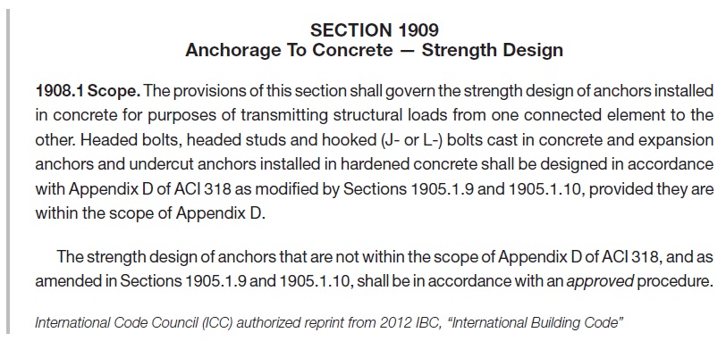
Cast-in-place headed bolts and headed studs used to resist earthquake loads or effects must be designed using “Strength Design” in accordance with ACI 318 Appendix D. Additionally, Section 1909 does not make reference to adhesive anchors, despite their status as “code anchors.” ACI 318-11 was the first edition to include adhesive anchors in its scope; however, the 2012 IBC was approved prior to the approval of ACI 318-11. This resulted in the omission of adhesive anchors from the language in Section 1909 of the 2012 IBC. Section 1901.3 of the 2015 IBC, entitled “Anchoring to Concrete” includes language for adhesive anchors and their applicability to the ACI 318-14 design and qualification requirements. The omission of adhesive anchors from Section 1909 of the 2012 IBC, however, does not exclude them from the design and qualification requirements of ACI 318-11 by virtue of their inclusion in ACI 318-11 Section D.2.2. The design professional must then reference Section D.2 of ACI 318-11, Appendix D to confirm that the anchors being designed fall within its scope.
Note that anchors used for temporary construction means, such as tilt wall panel bracing, are not addressed in the IBC. As a result, they are not required to be designed in accordance with the provisions of ACI 318, Appendix D. Section D.2.2 lists anchor types that fall within its scope, and those that are excluded (considered “Alternative Materials”).
Code Anchors are required to meet the ACI 318-11 Section D.2.3 qualification requirements described below.
ACI 355.2 (Qualification standard for expansion and undercut anchors) and ACI 355.4 (Qualification standard for adhesive anchors) are referenced here as the qualification criteria for specific types of postinstalled anchors. For the design professional it can be difficult to determine, without fully investigating these Referenced Standards, whether a specific proprietary anchor has been tested and is qualified for use in concrete. A simpler means by which to identify whether a proprietary anchor has been qualified to the Referenced Standard is a current Research Report (e.g., Evaluation or Code Report) which provides third-party review and verification that the product has been tested to and meets the qualification standard. There are two primary Research Report providers: IAPMO UES (International Association of Plumbing & Mechanical Officials Uniform Evaluation Service) and ICC-ES (International Code Council Evaluation Service).
These agencies are ANSI ISO 17065 accredited. They review independent laboratory test data, witnessed or conducted by an accredited third party, for a product and verify its conformance to publicly developed and majority-approved qualification criteria (or acceptance criteria) established for a given anchor type. Research Reports are an invaluable tool to the design professional and building official as evidence of conformance with the IBC.
There are two acceptance criteria that apply to post-installed “Code Anchors”:
- ICC-ES AC193 – Acceptance Criteria for Post-Installed Mechanical Anchors in Concrete Elements
- ICC-ES AC308 – Acceptance Criteria for Post-Installed Adhesive Anchors in Concrete Elements
These acceptance criteria reference ACI 355.2 and ACI 355.4, respectively, as the foundation for the test program by which the anchor is evaluated, and establish minimum performance standards for qualification. A Research Report is issued for an anchor that meets these minimum standards.
Deck Guardrail Update
This post is an update to David Finkenbinder’s post on Guard Post Resources from August 13.
As David explained, the requirements in the IRC and IBC for guards are intended to prevent people from falling off of raised surfaces. The failure of this guard is a common source of injuries caused by failures of deck components.
Section R312.1.1 of the 2012 International Residential Code (IRC) states that “Guards shall be located along open-sided walking surfaces, including stairs, ramps and landings, that are located more than 30 inches measured vertically to the floor or grade below at any point within 36 inches horizontally to the edge of the open side.”
Table 301.5 of the 2012 IRC requires that guards and handrails be designed for “[a] single concentrated load” of 200 pounds “applied in any direction at any point along the top.”
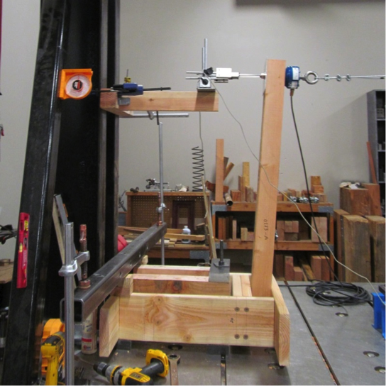
David mentioned the article Tested Guardrail Post Connections for Residential Decks, which described a testing program at Virginia Tech that examined the ability of various assemblies to resist this concentrated load at the top of the guard post. But rather than test in any direction, the researchers decided to test in what they considered the most critical direction: outward away from the deck.
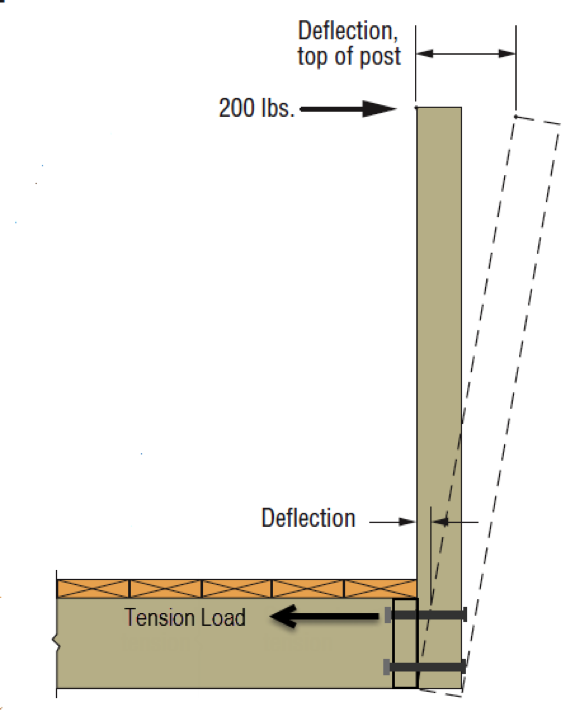
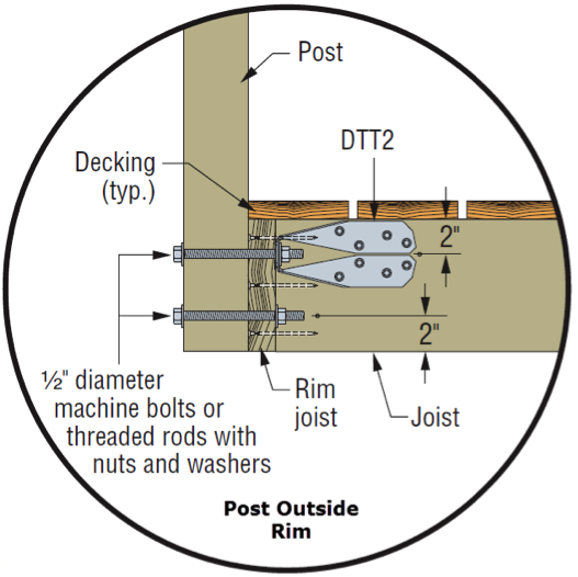
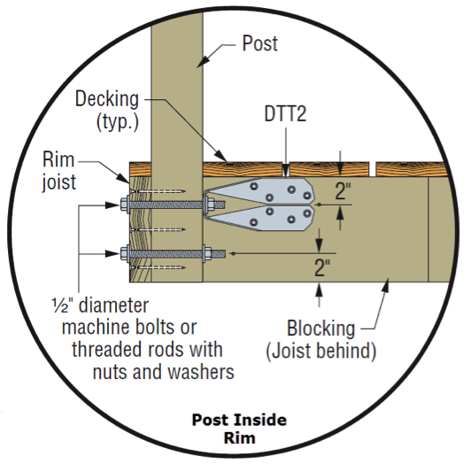
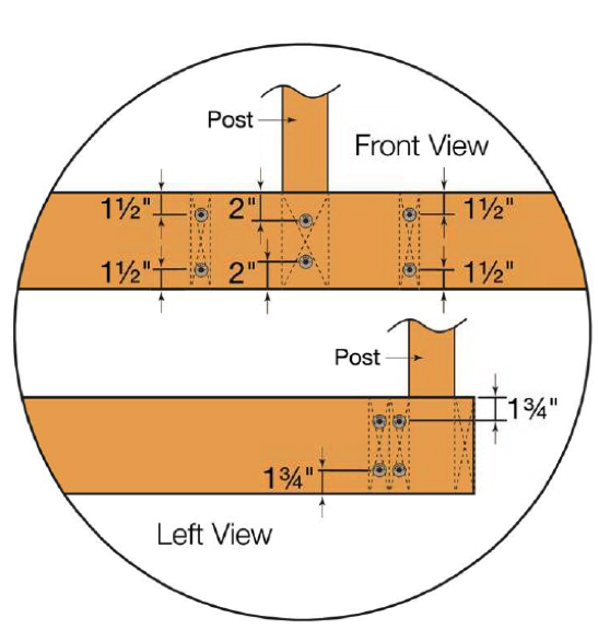
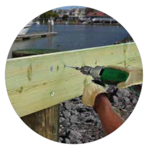
Simpson Strong-Tie subsequently developed a new tension tie, the DTT2Z, to make an economical connection from the top bolt in a deck post back into the framing of the deck to resist the high tension forces that develop in the top bolt when the top of the post is pushed outward. Several details were developed to try to address the various orientations of the post and deck framing.
To allow evaluation of assemblies used to resist this deck guardrail force, ICC-ES developed AC273, Acceptance Criteria for Handrails and Guards. AC273 is available for purchase through the ICC bookstore.
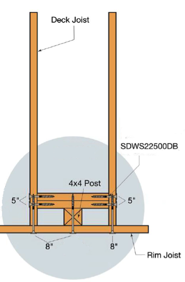
Even with the connectors being readily available, deck builders have asked for guard post connection details that do not involve the use of connection hardware. So Simpson Strong-Tie again tested several framing configurations according to the AC273 criteria, using our Strong-Drive® SDWS TIMBER screws and additional blocking to try to prevent the post from rotating. These details are shown in the engineering letter L-F-SDWSGRD15.
That brings us to the update part.
A committee made up of building officials, manufacturers, deck builders, designers and other interested parties is currently developing a set of code proposals on deck construction for inclusion in the 2018 International Residential Code (IRC). Even though more and more deck information has been incorporated into the last few editions of the IRC, there is still insufficient information in the code to be able to completely build a deck prescriptively. One area of interest is this guard connection. There is a desire to develop prescriptive details for both connection of a 4×4 post to deck framing with blocking and fasteners and for connecting the deck band joist back to the deck framing so that pre-manufactured guard rails can simply be fastened to the deck band with the knowledge that the connection is secure.
The problem is that, with the current requirement, the guard must resist the 200-pound load in ANY direction. All current testing, including AC273, only uses testing in the outward direction away from the floor of the deck. If the post were really required to resist a 200 pound load in the inward direction as well, then two hardware connectors would be required, one on each bolt. However, the belief of the committee is that resistance of 200 pounds in the outward and downward direction is primarily what is needed to ensure the safety of the occupants of the deck.
So they are working on a code proposal to change Table R301.5 of the IRC to require that the guard only resist the 200 pounds in the outward and downward direction and reduce the load to 50 pounds in the inward and upward direction.
The committee recognizes that while this is not necessarily a departure from current practice, it is a departure from current loading requirements in the IRC, IBC, and ASCE 7. So representatives of Simpson Strong-Tie met on September 30 with the NCSEA Code Advisory Committee – General Requirements Subcommittee to get the opinions of this group of active structural engineers. They provided valuable input, including the consideration that at some locations near landings and other changes in elevation, resistance to 200 pounds in the inward direction could be important.
Prior to incorporation of NCSEA’s input, the committee thought the code change might look as shown below.
We are interested in getting additional comments on this code proposal. What do you think? Let us know in the comments below.
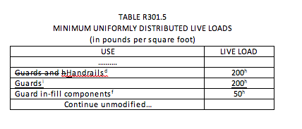
d) A single concentrated load applied in any direction at any point along the top, in pounds.
f) Guard in-fill components (all those except the handrail), balusters and panel fillers shall be designed to withstand a horizontally applied normal load of 50 pounds on an area equal to 1 square foot. This load need not be assumed to act concurrently with any other live load requirement.
h) Glazing used in handrail assemblies and guards shall be designed with a safety factor of 4. The safety factor shall be applied to each of the concentrated loads applied to the top of the rail, and to the load on the in-fill components. These loads shall be determined independent of one another, and loads are assumed not to occur with any other live load.
j) A single concentrated load applied at any point along the top, in pounds. The 200-pound load is required to be applied in either the outward or downward direction, and it is permitted to be reduced to 50 pounds in either the inward or upward direction. The guard is not required to resist these loads applied concurrently with each other.
Accommodating Truss Movement (Besides Vertical Deflection)
Vertical deflection resulting from live and dead loads – of both roof and floor framing components – is an important serviceability consideration in the overall design of the building. And while this could be a blog topic in and of itself, this post is instead going to focus on two other types of truss movements that often prompt questions: seasonal up-and-down movement (of the trusses relative to the walls) and horizontal movement (of scissor trusses).
On the one hand, these are completely different topics. But on the other hand, they both deal with movement; which needs to be properly addressed when incorporating trusses into the overall building. So it’s sensible to discuss them together in one blog post.
Seasonal Up-and-Down Movement
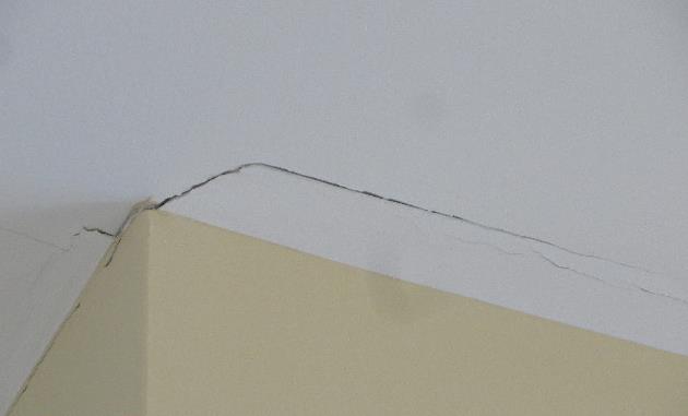
This type of movement goes by many different names that might sound familiar – truss arching, truss uplift, partition separation, or – to use the most formal name – ceiling-floor partition separation. All of these names describe the separation that develops between interior partition walls and ceiling finishes, which can cause gaps in the drywall to open in the winter and close in the summer. This movement is often considered to be a truss issue; however, it is not always the trusses that do the moving, but rather the walls or floors, or both, beneath the trusses.
This issue is also not limited to truss construction, but can also occur with other types of wood construction. The truss industry has information on this topic to help educate the market about the causes of ceiling-floor partition separation, best practices and construction techniques for minimizing the movement, and how to accommodate this movement in the structure to prevent drywall cracking.
For those who are interested in a very thorough and technical discussion of this issue and all of the factors that can contribute to it, there is a Technical Note available from the Truss Plate Institute (TPI) called Ceiling-Floor Partition Separation: What Is It and Why Is It Occurring? Although it was written several years ago (by the Small Homes Council-Building Research Council), the information remains relevant because the problem and its causes are the same now as they were then. The Technical Note discusses the potential causes of ceiling-floor partition separation, which may include one or more of the following: attic moisture (and the differential shrinkage and swelling of truss chords due to seasonal changes in moisture content), foundation settlement, expansive soils, excessive cumulative shrinkage of wood framing members and errors made during the construction process such as pulling the camber out of a truss to attach it to a partition. There is even an Appendix with a brief discussion of longitudinal shrinkage and an example calculation showing how much upward deflection results when a truss arches because of differential shrinkage.
For a condensed version, there is also a document available from the Structural Building Components Association (SBCA) called “Partition Separation Prevention and Solutions (How to Minimize Callbacks Due to Gypsum Cracking at the Wall/Ceiling Interface)”. This single-page document is particularly useful for educating the industry to take the appropriate preventive measures during construction, which help minimize problems later.
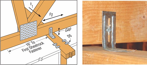
For example, the use of slotted roof truss clips – such as our STC (see below) – is one preventive measure, since these clips allow for vertical movement, but still provide lateral support at the top of the wall. DS drywall clips can be used in conjunction with the STC clips to secure the drywall to the wall. Then, to allow the drywall ceiling to “float,” the drywall is not fastened to the bottom chord within 16” from the wall. Taking these steps allows movement between the truss and the wall, without causing cracking in the drywall at the wall/ceiling interface.
It is important to note that, while foundation settlement may indicate a structural problem and can be prevented by proper design, truss arching resulting from the natural shrinking/swelling of wood does not indicate any structural problem and cannot be avoided in the design process.
Horizontal Movement of Scissor Trusses
In the typical design of a scissor truss, a pin-type bearing is used at one end, and a roller-type bearing is used at the other end, which results in some amount of horizontal deflection at the roller bearing.
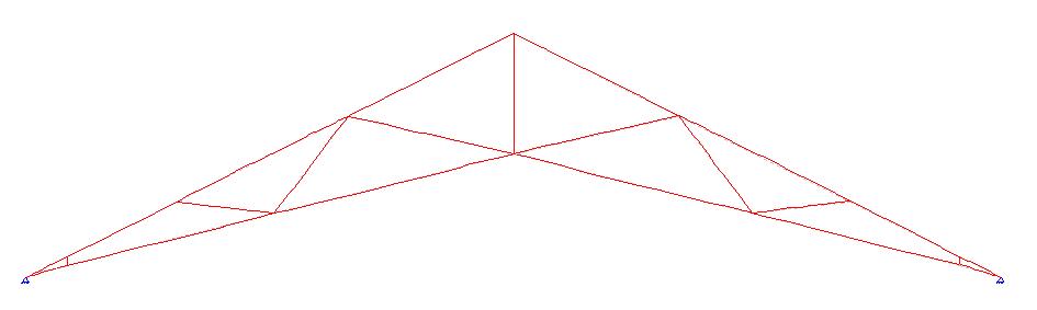
The bearing assumptions used in the design of a scissor truss are important not only to the truss, but they also have design implications for the building as well. Using a pin-type bearing at both ends of the truss has undoubtedly been a temptation to every truss technician at one time or another, when the same scissor truss that is failing the analysis suddenly works as soon as the bearings are switched from pin-roller to pin-pin. Unfortunately, that isn’t a valid option unless the walls are infinitely stiff (which they typically aren’t), or unless special measures are taken to resist the horizontal thrust that develops at the pinned reactions. In most cases, such measures won’t be taken which means with the exception of some rare cases, scissor trusses must be designed with pin-roller bearings.
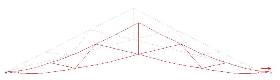
The horizontal deflection that results when a scissor truss is designed with a roller bearing on one end prompts further questions and discussion. What happens when a scissor truss is rigidly secured to the walls of the building – how does that horizontal movement happen? How much horizontal movement is too much? Should the scissor truss be attached to the wall with a sliding (roller-like) connection?
First, a scissor truss that is rigidly secured to both walls will still experience horizontal movement due to the flexibility of the building’s construction in most residential and light commercial construction. How much horizontal movement is too much for the building? This is definitely a question that the Building Designer needs to answer based on his/her evaluation of the overall structure. However, there are a couple of resources that can provide some insight.
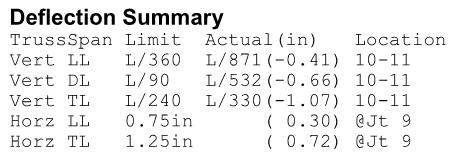
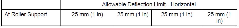
ANSI/TPI 1 has the following provision:
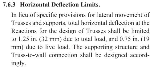
Per ANSI/TPI 1, a scissor truss can have up to 1.25″ of total horizontal deflection in the absence of stricter limits from the Building Designer. Scissor trusses may even be designed with more than this amount of horizontal deflection, along with a warning that special provisions for lateral movement may be required. It is important for the Building Designer to be aware of the calculated horizontal movement of the scissor truss, as reported on the truss design drawing, to ensure that it is an acceptable amount of horizontal movement for the supporting structure and/or to determine whether special provisions for the lateral movement need to be made.
While 1.25″ of total horizontal deflection may seem like a lot of horizontal movement, these calculated horizontal deflections are considered to be conservative; many Designers agree that the predicted movement from the pin-roller bearing combination is greater than will actually occur in the constructed building. This is based on the fact that the design loads may be overstated and the contribution of the sheathing (and drywall if applicable) to resist the horizontal movement is not taken into account during the analysis of the truss.
The National Building Code of Canada (NBC) references Section 5.4.4 of the 2009 Engineering Guide for Wood Frame Construction, which limits lateral movement at the top of each wall to h/500. This correlates to a total allowable horizontal movement of 3/8″ for 8ˈ walls. However, the Canadian truss design standard (TPIC-2014) permits trusses to have a horizontal deflection (at the roller support) of up to 1″. In this case, since the horizontal deflection of the truss exceeds the allowable horizontal deflection of the wall, a sliding connection needs to be used between the truss and the wall.
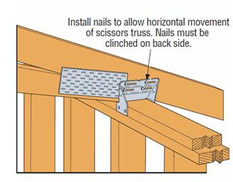
There are different opinions on the use of sliding connections, such as the slotted TC24 or TC26 connectors (see below), which allow for horizontal movement of the trusses without pushing out the wall, and also provide uplift resistance. The use of these clips also varies greatly by region. There are many places where these clips are used regularly and successfully. However, some Designers prefer to restrict the truss horizontal deflection and require the use of a positive connection between the scissor truss and the wall plate due to concerns regarding the transfer of lateral loads from the top of wall to the roof diaphragm. When TC connectors are used, they are often used on alternating ends of the trusses so that there is a positive connection along each wall at every other truss. Some Designers feel this approach minimizes the horizontal movement between the truss and the wall after the building is constructed and fully sheathed and braced.
There is not a single correct answer to address horizontal truss movement for every building. The amount of horizontal movement that is acceptable for the structure and whether or not a sliding connection should be used will depend on the building, the loading conditions, the designer’s experience and/or judgment, and, in some cases, the local building jurisdiction. What is more important than the decision to either restrict horizontal deflection or utilize sliding connectors like the TC24/TC26 (both have been successful) is that the bearing assumptions used in the design of the scissor truss are accounted for in the design of the building. The worst-case scenario is when a scissor truss is designed with a pin-pin bearing and installed in a building where absolutely no measures have been taken to supply the needed resistance to the calculated horizontal thrust.
What are your thoughts or experiences with either seasonal up-and-down movement or horizontal movement? Let us know in the comments below!
Reminders from Hurricane Katrina
This week is the 10th anniversary of Hurricane Katrina, and we have all seen articles on the lessons learned from the storm. Engineers learn something new from every storm. However, I think that Hurricane Katrina just gave us some very strong reminders of things we already knew.
Hurricane Katrina reminded us that hurricanes are flood events as well as high-wind events. And I don’t mean the flooding in New Orleans. No, I mean the flooding along the Gulf Coast from Louisiana to Florida.
I witnessed the complete devastation of the Mississippi Gulf Coast from Waveland to Biloxi. Structures within the first few (and often many) blocks from the beach were simply flattened by water. Fortunately, these areas are coming back, but the structures being built there now bear little resemblance to the homes that graced the beach 10 years ago.
I remember my father-in-law having his new house built on the coast in Waveland more than 20 years ago. As a young engineer, I gave it the once over and noted that the builder had connected the roof framing to the top plate, but little else. I made some recommendations, such as continuing the connections down throughout the rest of the house to the foundation. The builder followed my suggestions and then presented my father-in-law with the bill “for your son-in-law the inspector.” He was happy to pay it. Nevertheless, although the house was wind resistant, it could not stand up to the rushing waters from Hurricane Katrina.
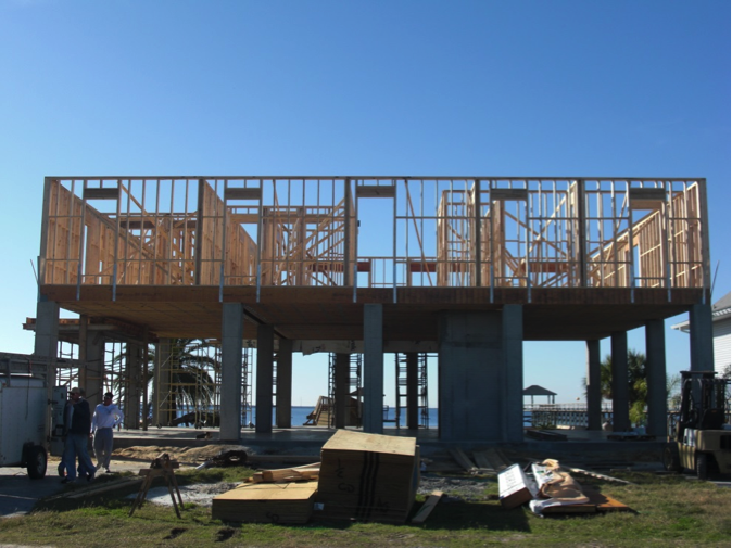
Katrina reminds us that the only way to get away from floods, other than not building near the water, is to elevate structures above them. Due to flood regulations, new houses along the Gulf Coast are now elevated high in the air, in the hope of avoiding flooding from future storms. Simpson Strong-Tie is proud to have developed some products during the last few years that make it easier to build structures elevated on pilings.
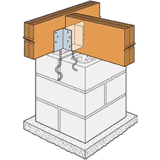
One such product is our CCQM column cap that strengthens the connection of support beams to masonry piers. Another is the Strong-Drive® SDWH Timber-Hex HDG structural screw, which is meant to replace through-bolts to make the connection of a beam to a wood piling easier and more reliable.
Hurricane Katrina reminds us of the value of building codes. After the storm, the LSU Hurricane Center conducted a number of simulation studies on the effect of a direct, Katrina-like storm on the states of Louisiana, Mississippi and Alabama. The simulations were run on the existing stock of buildings, and then run again on the same stock of buildings, assuming that certain features that result from modern building codes were present. These features included shutters or impact-resistant windows, enhanced nailing of the roof deck to the roof framing, framing connected together with hurricane clips and straps to achieve a continuous load path. In addition, in the Louisiana study, a secondary water barrier over the joints in the roof sheathing was added.
The studies found that the decrease in wind damage from the simulated storms was astounding. In Louisiana, the study showed a 79% reduction in economic losses due to wind. In Alabama, the study revealed a 72% reduction in economic losses due to wind. The Gulf states seem to have received the message loud and clear. In the years following Hurricane Katrina, Louisiana adopted a statewide building code and Mississippi adopted a uniform building code for the four counties along the coast. Recently, Alabama has also adopted a statewide residential and energy code. But in general, building codes are still quite varied in coastal states. This report from the Insurance Institute for Business and Home Safety evaluates the effectiveness of building codes in coastal states.
Finally, Hurricane Katrina reminds those of us who do damage surveys that you need to know what you are getting into before you go. As soon as the storm hit and we saw the scope of the damage, four members of the Simpson Strong-Tie Engineering Department in our McKinney, Texas, office decided we needed to go see the damage first-hand before any repairs were made. So two days after the storm struck, off we went to Jackson, Mississippi. There, we rented two vans stocked up with food, water and fuel. Unfortunately, the fuel and the food/water ended up in separate vans. Before long, we were separated in traffic and could not communicate due to loss of cell signal.
Our team spent two days viewing the damage first-hand along the Louisiana and Mississippi coast, but spent a lot of time our last day trying to find some fuel so we could make it back to Jackson. I remember spending the night in a hotel without power full of storm victims, and then months later receiving the bill and being charged for a movie!


What do you remember from Hurricane Katrina? Let us know in the comments below.
Seismic Bracing Requirements for Nonstructural Components
Have you ever been at home during an earthquake and the lights turned off due to a loss of power? Imagine what it would be like to be in a hospital on an operating table during an earthquake or for a ceiling to fall on you while you are lying on your hospital bed.
“You Cannot Escape Responsibility Tomorrow by Evading it Today”
While the contents of this blog are certainly not what Abraham Lincoln had in mind when he made the statement that I’m using to title this blog post, it does speak volumes to the pertinence of what will be discussed today. “Design by others” or some variation of this appears in many parts of Simpson Strong-Tie details.Continue Reading