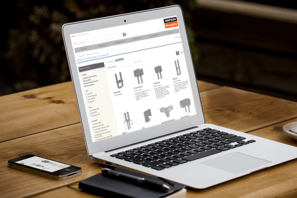
We know many of you visit our website on a regular basis for product and technical information and to use our software, calculator tools and other web apps. If you haven’t visited strongtie.com recently, it has a new look and several new features, including enhanced search and browsing and a mobile-friendly design. Here are some of the new features and site improvements:
Update-to-date product information: If there is a new code report, catalog or product you will be able to find that information on our new website first. It has the latest product and technical information while retaining the same features and information you expect.
Enhanced search and browsing: You can now search for our products based on specific product attributes. Our enhanced search capabilities allow you to explore our collection of products by applying filters so you can quickly and easily browse and find the products that you are looking for.
Mobile-friendly: Our new site has a responsive design that allows you to view the site in any format. From large desktops to mobile devices, you can view our site in the office or while on the go.
Enhanced Visuals: We have added new and improved photographs, illustrations and graphics so that you can see our products in greater detail.
We hope the new website better serves your design and technical needs. If you have any suggestions, comments or feedback, please email us at web@strongtie.com or leave a comment below.
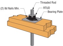
Over the weekend, I had the pleasure of watching my daughter in her cheer competition. I was amazed at all the intricate detail they had to remember and practice. The entire team had to move in sync to create a routine filed with jumps, tumbles, flyers and kicks. This attention to detail reminded me of the new ratcheting take-up device (RTUD) that Simpson Strong-Tie has just developed to accommodate 5/8″ and ¾” diameter rods. The synchronized movement of the internal inserts allows the rod to move smoothly through the device as it ratchets. The new RTUDs are cost effective and allow unlimited movement to mitigate wood shrinkage in a multi-story wood- framed building. When designing such a building, the Designer needs to consider the effect of shrinkage and how to properly mitigate it.
Shrinkage is natural in a wood member. As moisture reaches its equilibrium in a built environment, the volume of a wood member decreases. The decrease in moisture causes a wood-framed building to shrink.
The IBC allows construction of light-framed buildings up to 5 and 6 stories in the United States and Canada respectively. Based on the type of floor framing system, the incremental shrinkage can be up to ¼” or more per floor. In a 5-story building, that can add up to 1-¼” or more and possibly double that when construction settlement is included.
Typical Example of gap forming between nut and plate when wood shrinkage at top level occurs without shrinkage device.
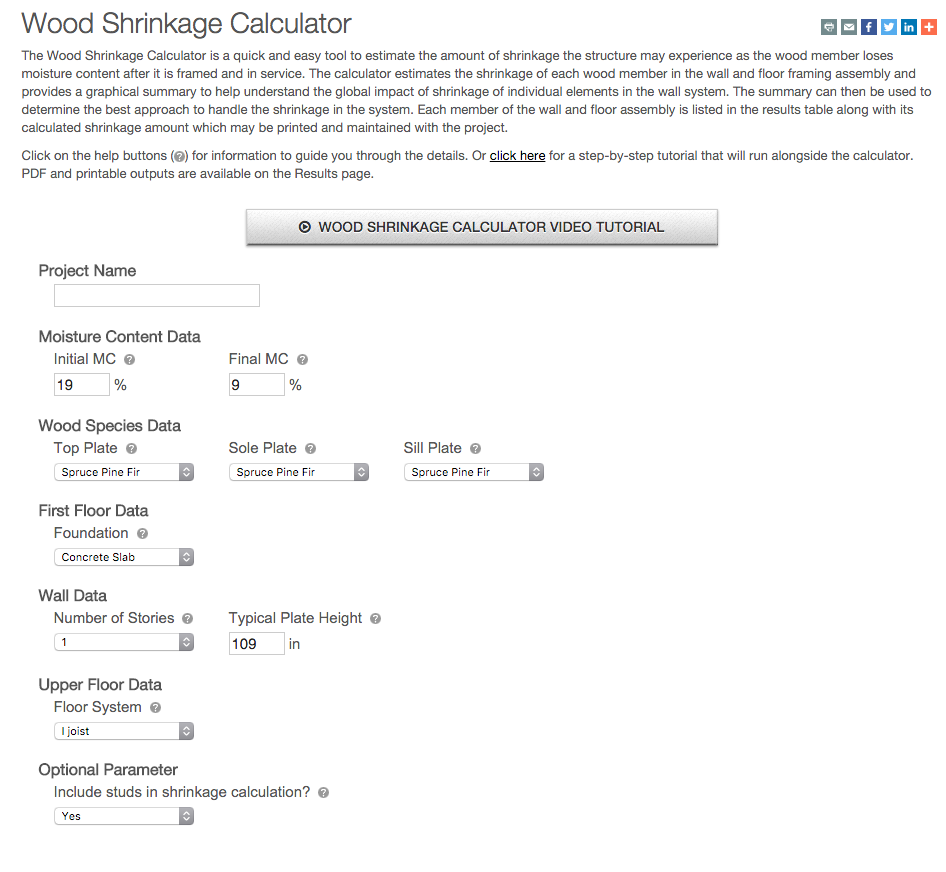
The Simpson Strong-Tie Wood Shrinkage Calculator is a perfect tool to determine the total shrinkage your building can experience.
Wood Shrinkage Calculator
In order to accommodate the shrinkage that occurs in a multi-story wood-framed building, Simpson Strong-Tie offers several shrinkage compensating devices. These devices have been tested per ICC-ES Acceptance Criteria 316 (AC316) and are listed under ICC-ES ESR-2320 (currently being updated for the new RTUD5, RTUD6, and ATUD9-3).
AC316 limits the rod elongation and device displacement to 0.2 inches between restraints in shearwalls. This deflection limit is to be used in calculating the total lateral drift of a light-framed wood shearwall.
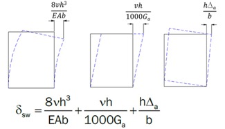
3 Part Shearwall Drift Equation
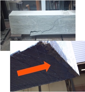
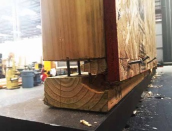
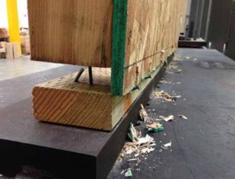
The 0.2-inch allowable limit prescribed in AC316 is important to a shearwall’s structural ability to transfer the necessary lateral loads through the structure below to the foundation level. This limit assures that the structural integrity of the nails and sill plates used to transfer the lateral loads through the shearwalls is not compromised during a seismic or wind event. Testing has shown that sill plates can crack when excessive deformation is observed in a shearwalls. Nails have also been observed to pull out during testing. Additional information on this can be found here.
Sill Plates Cracked due to excessive uplift at ends of shearwall.Nails pull out due to excessive uplift at ends of shearwall.
In AC316, 3 types of devices are listed.
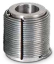
Compression-Controlled Shrinkage Compensating Device (CCSCD): This type of device is controlled by compression loading, where the rod passes uninterrupted through the device. Simpson Strong-Tie has several screw-type take-up devices, such as the Aluminum Take-Up Device (ATUD) and the Steel Take-Up Device (TUD), of this type.
ATUD (CCSCD)
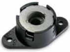
Tension-Controlled Shrinkage Compensating Device (TCSCD): This type of device is controlled by tension loading, where the rod is attached or engaged by the device and allows the rod to ratchet through as the wood shrinks. The Simpson Strong-Tie Ratcheting Take-Up Device (RTUD) is of this type.
RTUD (TCSCD)
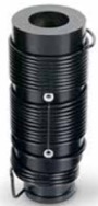
Tension-controlled Shrinkage Compensating Coupling Device (TCSCCD): This type of device is controlled by tension loading that connects rods or anchors together. The Simpson Strong-Tie Coupling Take-Up Device (CTUD) is of this type.
CTUD (TCSCCD)
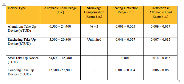
Each device type has unique features that are important in achieving the best performance for different conditions and loads. The following table is a summary of each device.
The most cost-effective Simpson Strong-Tie shrinkage compensation device is the RTUD. This device has the smallest number of components and allows the rod unlimited travel through the device. It is ideal at the top level of a rod system run or where small rod diameters are used. Simpson Strong-Tie RTUDs can now accommodate 5/8″ (RTUD5) and ¾” (RTUD6) diameter rods.
How do you choose the best device for your projects? A Designer will have to consider the following during their design.
RTUD Assembly
Rod Tension (Overturning) Check:
Rods at each level designed to meet the cumulative overturning tension force per level
Standard and high-strength steel rods designed not to exceed tensile capacity as defined in AISC specification
Standard threaded rod based on 36 / 58 ksi (Fy/Fu)
High-strength Strong-Rod based on 92 / 120 ksi (Fy/Fu
H150 Strong-Rod based on 130 / 150 ksi (Fy/Fu)
Rod elongation (see below)
Bearing Plate Check
Bearing plates designed to transfer incremental overturning force per level into the rod
Bearing stress on wood member limited in accordance with the NDS to provide proper bearing capacity and limit wood crushing
Bearing plate thickness has been sized to limit plate bending in order to provide full bearing on wood member
Shrinkage Take-Up Device Check
Shrinkage take-up device is selected to accommodate estimated wood shrinkage to eliminate gaps in the system load path
Load capacity of the take-up device compared with incremental overturning force to ensure that load is transferred into rod
Shrinkage compensation device deflection is included in system displacement
Movement/Deflection Check
System deformation is an integral design component impacting the selection of rods, bearing plates and shrinkage take-up devices
Rod elongation plus take-up device displacement is limited to a maximum of 0.2″ per level or as further limited by the requirements of the engineer or jurisdiction
Total system deformation reported for use in Δa term (total vertical elongation of wall anchorage system per NDS equation) when calculating shearwall deflection
Both seating increment (ΔR) and deflection at allowable load (ΔA) are included in the overall system movement. These are listed in the evaluation report ICC-ES ESR-2320 for take-up devices
Optional Compression Post Design
Compression post design can be performed upon request along with the Strong-Rod System
Compression post design limited to buckling or bearing perpendicular to grain on wood plate
Anchorage design tools are available
Anchorage design information conforms to AC 318 anchorage provisions and Simpson Strong-Tie testing
In order to properly design a continuous rod tie-down system for your shearwall overturning restraint, all of the factors listed above will need to be taken into consideration.
A Designer can also contact Simpson Strong-Tie by going to www.strongtie.com/srs and filling out the online “Contact Us” page to have Simpson Strong-Tie design the continuous rod tie-down system for you. This design service does not cost you a dime. A few items will be required from the Designer in order for Simpson Strong-Tie to create a cost-effective rod run (it is recommended that on the Designer specify these in the construction documents):
There is a maximum system displacement of 0.2″ per level, which includes rod elongation and shrinkage compensation device deflection. Some jurisdictions may impose a smaller deflection limit.
Bearing plates and shrinkage compensation devices are required at every level.
Cumulative and incremental forces must be listed at each level in Allowable Stress Design (ASD) force levels.
Construction documents must include drawings and calculations proving that design requirements have been met. These drawings and calculations should be submitted to the Designer for review and the Authority Having Jurisdiction for approval.
More information can be obtained from our website at www.strongtie.com/srs, where a new design guide for the U.S., F-L-SRS25, and a new catalog for Canada, C-L-SRSCAN22, are available for download.
US Design Guide F-L-SRS25 and Canadian Catalog C-L-SRSCAN22
As many of you know, LinkedIn is a social networking website specifically aimed at business professionals and is designed to help you connect and network with people you know and trust. You can add colleagues, peers and others as contacts and send them messages. You can create and update your personal profile to let your contacts know about your professional activities, and both recommend or endorse your contacts and get recommended or endorsed by your contacts for your professional skills. In addition, you can join groups to communicate with other professionals within the same sector or industry. You are also able to ask and answer industry-related questions, and to learn about and apply for job openings.
A basic membership on LinkedIn is free, but you can also upgrade your account in order to have access to professionals outside of your network.
To help guide you, here are some best practices for how to set up and optimize your LinkedIn account.
Update and Complete Your Profile
Having a complete and updated profile on LinkedIn allows you to put your best face forward. Make sure to summarize your role and responsibilities and current and past work experience, highlighting the details you think will make a prospective customer want to work with you. Include a professional-looking headshot and your current contact information. LinkedIn will even tell you your profile strength on the right-hand rail.
Join Industry Specific Groups
Joining groups that are relevant to our industry will allow you to participate in online industry discussions. Answering questions related to your field of expertise within these discussions is an excellent way to position yourself as an authority and build your professional reputation. Here are some structural engineering groups that you can start with:
Connect with people you already know using your email contacts. This will help you maintain your existing relationships as well as branch out to connect with industry-related people your contacts may know. Another great feature of LinkedIn is that it will tell you “People You May Know” based on where you work or are already linked to. This feature will help you find meaningful connections.
Follow the Company Page and Share Posts
Simpson Strong-Tie has a company LinkedIn page to connect with customers. Company pages are a way to keep up to date on trends in design and building materials, code changes, product launches and other industry news. Make sure to follow the Simpson Strong-Tie company page so that you can stay informed about our latest news and updates.
Manage Privacy Settings
Make sure to review and manage your privacy settings to help you control how many people can view your activities and personal information. You can do this by hovering your mouse on your thumbnail image on the far right- hand side of your home page.You should see an Account & Settings drop-down menu appear with an option that says “Privacy & Settings: Manage.” Click this option. Once you are there, you can manage all of your privacy settings.
How do you use LinkedIn as part of your engineering career? Let us know in the comments below.
This week’s post comes from Brad Erickson, who is the Engineering Manager for the Composite Strengthening Systems™ product line at our home office. Brad is a licensed civil and structural engineer in the State of California and has worked in the engineering field for more than 17 years. After graduating from Cal Poly, San Luis Obispo with a B.S. in Architectural Engineering, he worked for Watry Design, Inc. as an Associate Principal before coming to Simpson Strong-Tie. Brad is the Engineering Manager for Composite Strengthening Systems and his experience includes FRP design, masonry and both post-tensioned and conventional concrete design. While not at work, Brad enjoys spending time carting his three kids around to their competitive soccer games and practices.
Have you ever had a concrete or masonry design project where rebar was left out of a pour? Chances are, the answer is yes. Did you wish you could solve this problem by putting rebar on the outside of that element? That’s exactly what Simpson Strong-Tie Composite Strengthening Systems™ (CSS) can do for you and your project. In effect, composites act like external rebar for your concrete or masonry element. Composites can be used in similar configurations to rebar but are applied on the exterior surface of the element being strengthened.
The initial offering in our CSS line is our fiber-reinforced polymer (FRP) product group. An FRP composite is created by taking carbon or glass fabric and saturating it with a two-part epoxy which, when cured, creates the composite. Together, the weight of the fabric and the number of layers in the composite determine how much strength it will add to your concrete or masonry element.
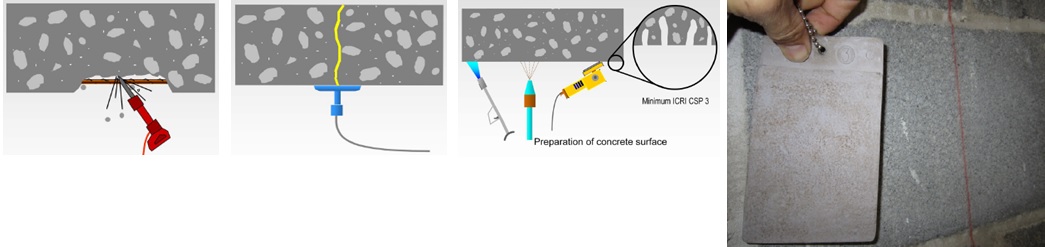
Another form of FRP composite is a precured carbon laminate. The carbon fibers are saturated in the manufacturing facility and are attached to the structure using CSS-EP epoxy paste and filler, an epoxy with a peanut butter–like consistency. We also carry paste profilers (pictured below) that help contractors apply the proper amount of paste to a piece of precured laminate.
Of course, before any concrete or masonry reinforcement project can succeed, proper surface preparation is of the utmost importance. Without a good bond with the substrate, a composite will not be able to achieve the intended performance. Concrete voids must be repaired, cracks must be injected and sealed, and any deteriorated rebar must be cleaned and coated. Prior to composite placement, the surface of the substrate must be prepared to CSP-3 (concrete surface profile) in accordance with ICRI Guideline No. 310.2. Grinding and blasting are the most common surface-preparation techniques.
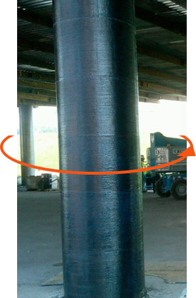
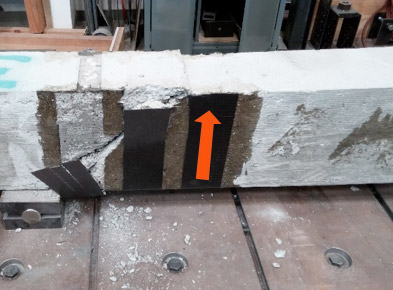
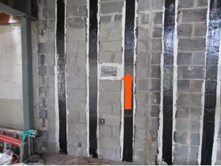
The following are just a few applications where composites can be used for concrete and/or masonry retrofits. The orange arrows show the direction of the fibers in the fabric – in other words, the direction in which the composite provides tension reinforcement.
This is a summary of the basics of composites and their installation on strengthening projects. As composites are not yet in the design codes in the United States, the American Concrete Institute has produced 440.2R-08: Guide for the Design and Construction of Externally Bonded FRP Systems for Strengthening Concrete Structures. This guide has numerous recommendations for using fiber-reinforced polymer systems to strengthen your concrete or masonry construction.
If you would like more information about FRP design, you can learn the best practices for fiber-reinforced polymer (FRP) strengthening design during a recorded webinar offered by Simpson Strong-Tie Professional Engineers. We look at FRP components, applications and installation. We also take you behind the scenes to share the evaluation process informing a flexural beam-strengthening design example and talk about the assistance and support Simpson Strong-Tie Engineering Services offers from initial project assessment to installation.
In this free webinar we dive into some very important considerations including the latest industry standards, material properties and key governing limits when designing with FRCM.
Continuing education credits will be offered for this webinar.
Participants can earn one professional development hour (PDH) or 0.1 continuing education unit (CEU).
For complete information regarding specific products suitable to your unique situation or condition, please visit strongtie.com/rps or call your local Simpson Strong-Tie RPS specialist.
Simpson Strong-Tie is sponsoring the 24th Short Course on Cold-Formed Steel Structures hosted by the Wei-Wen Yu Center for Cold-Formed Steel Structures (CCFSS). The course will be held on October 27-29, 2015 at the Drury Plaza Hotel at the Arch in St. Louis, MO.
This three-day course is for engineers who have limited or no experience designing with cold-formed steel (CFS), as well as those with experience who would like to expand their knowledge of cold-formed steel structural design. Lectures will be given by industry-recognized experts Roger LaBoube, Ph.D., P.E., and Sutton Stephens, Ph.D., P.E., S.E. The course is based on the 2012 AISI North American Specification for the Design of Cold-Formed Steel Structural Members and the 2012 North American Standards for Cold-Formed Steel Framing. Dr. Wei-Wen Yu’s book Cold-Formed Steel Design (4th Edition) will be a reference text.
The course will address such topics as design of wall studs, floor joists, purlins, girts, decks and panels. It is eligible for 2.4 Continuing Education Units (CEUs). Advance registration is requested by October 10, 2015. For more information and to register, click here.
While consideration of bracing is important for any structural element, this is especially true for thin, singly symmetric cold-formed steel (CFS) framing members such as wall studs. Without proper consideration of bracing, excessive buckling or even failure could occur. Bracing is required to resist buckling due to axial or out-of-plane lateral loads or a combination of the two.
There are two methods for bracing CFS studs as prescribed by the American Iron and Steel Institute (AISI) Committee on Framing Standards (COFS) S211 “North American Standard for Cold-Formed Steel Framing – Wall Stud Design” Section B1. One is sheathing braced design and the other is steel braced design.
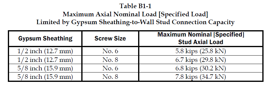
Sheathing braced design has limitations, but it is a cost effective method of bracing studs since sheathing is typically attached to wall studs. This design method is based on an assumption that the sheathing connections to the stud are the bracing points and so it’s limited by the strength of the sheathing fastener to stud connection. Due to this limitation, the Designer has to use a steel braced design for most practical situations. AISI S211 prescribes a maximum nominal stud axial load for gypsum board sheathing with fasteners spaced no more than 12 inches on center. AISI S211 Section B1 and the Commentary discuss the design method and assumptions and demonstrate how to determine the sheathing bracing strength.
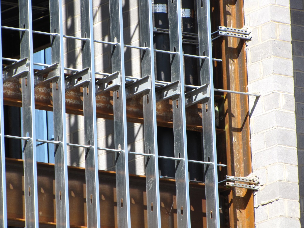
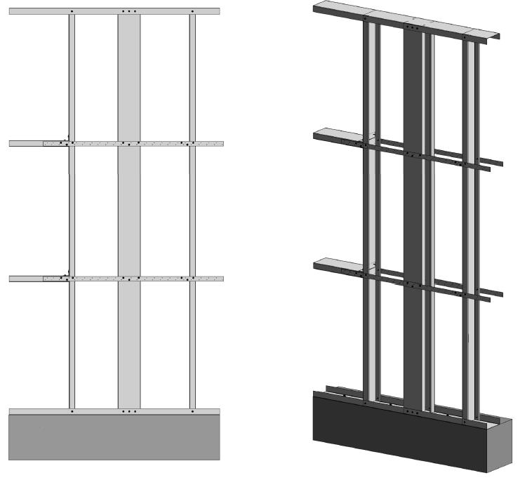
CFS Curtain Wall Stud Steel Clip and Bridging Bracing
Sheathing braced design requires that identical sheathing is used on each side of the wall stud, except the new AISI S240 standard Section B1.2.2.3 clarifies that for curtain wall studs it is permissible to have sheathing on one side and discrete bracing for the other flange not spaced further than 8 feet on center. The wall stud is connected to the top and bottom tracks or supporting members to provide lateral and torsional support and the construction drawings should note that the sheathing is a structural element. When the sheathing on either side is not identical, the Designer must assume the weaker of the two sheathings is attached to each side. In addition, the Designer is required to design the wall studs without the sheathing for the load combination 1.2D + (0.5L or 0.2S) + 0.2W as a consideration for construction loads of removed or ineffective sheathing. The Designer should neglect the rotational restraint of the sheathing when determining the wall stud flexural strength and is limited by the AISI S100 Section C5.1 interaction equations for designing a wall stud under combined axial and flexural loading.
Steel braced design may use the design methodology shown in AISI S211 or in AISI Committee on Specifications (COS) S100 “North American Specification for the Design of Cold-Formed Steel Structural Members.”
AISI S211 Table B1-1 Maximum Axial Nominal Load Limited by Gypsum Sheathing-to-Wall Stud Connection Capacity
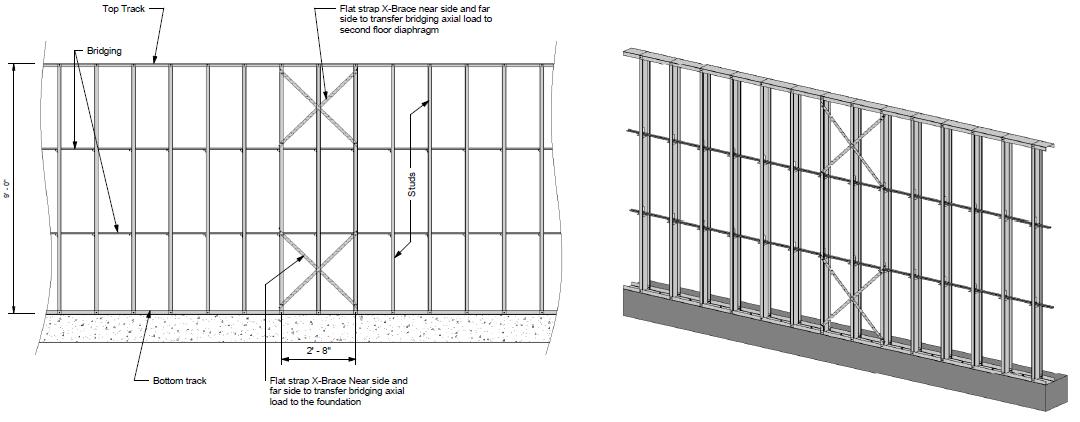
Steel braced design is typically either non-proprietary or proprietary “clip and bridging” bracing, or “flat strap and blocking” bracing periodically spaced along the height of the wall stud.
Steel braced design is a more practical bracing method for several reasons. First, during construction, wall studs go unsheathed for many months, but are subjected to significant construction loads.This is especially true for load-bearing, mid-rise structures. Second, some sheathing products, including gypsum wallboard, can be easily damaged and rendered ineffective if subjected to water or moisture. Third, much higher bracing loads can be achieved using mechanical bracing. IBC Section 2211.4 permits Designers to design steel bracing for axially loaded studs using AISI S100 or S211. However, S100-07 requires the brace to be designed to resist not only 1% of the stud nominal axial compressive strength (S100-12 changes this to 1% of the required compressive axial strength), but also requires a certain brace stiffness. S211 requires the Designer to design the bracing for 2% of the stud design compression force, and it does not have a stiffness requirement. . AISI S100 is silent regarding combined loading, but S211 provides guidance. S211 requires that, for combined loading, the Designer designs for the combined brace force determined using S100 Section D3.2.1 for the flexural load in the stud and either S100 or S211 for the axial load. In addition, the bracing force for stud bracing is accumulative as stated by S211 Commentary section B3. As a result, the periodic anchorage of the bracing to the structure such as strongbacks or diagonal strap bracing is required.
Some benefits and challenges of steel clip and bridging bracing include:
Proprietary solutions, such as the Simpson Strong-Tie SUBH bridging connector, can significantly reduce installed cost since many situations require only one screw at each connection.
Unlike strap bracing, u-channel bracing can be installed from one side of the wall.
U-channel bracing does not create build-up that can make drywall finishing more difficult.
Extra coordination may be required to ensure that u-channel bridging does not interfere with plumbing and electrical services that run vertically in the stud bay.
Bracing for axial loaded studs requires periodic anchorage to the structure, such as using strongbacks or diagonal strap bracing.
Bracing of laterally loaded studs does not require periodic anchorage since the system is in equilibrium as torsion in the stud is resisted by bridging (e.g., U-channel) bending.
Some benefits and challenges of steel flat strap and blocking bracing include:
May be installed at other locations than stud punchout.
Required to be installed on both sides of wall.
Bumps out sheathing.
Bracing for axial loaded studs requires periodic anchorage to structure, such as using strongbacks or diagonal strap bracing (same load direction in stud flanges).
Bracing for laterally loaded studs requires design of periodic blocking or periodic anchorage to the structure (opposite load direction in stud flanges).
There are several good examples Designers may reference when designing CFS wall stud bracing. They include AISI D110 Cold-Formed Steel Framing Design Guide that may be purchased from www.cfsei.org, SEAOC Structural/Seismic Design Manual Volume 2 Example 3 that may be purchased from www.seaoc.org, and the Simpson Strong-Tie wall stud steel bracing design example on page 60 of the C-CFS-15 CFS catalog.
Cold-formed steel framing is a versatile construction material, but Designers need to carefully consider the bracing requirements of the AISI specification and wall stud design standard. What cold-formed steel wall bracing challenges have you encountered and what were your solutions?
This year, the new 5th Edition of the Florida Building Code was released and is now in effect statewide. First printed in 2002, the Florida Building Code was developed as part of Florida’s response to the destruction caused by Hurricane Andrew and other hurricanes in the state.
Another component, which I would like to take a closer look at in today’s post, is a separate Florida Product Approval system designed to be a single source for approval of construction products for manufacturers, Designers and code enforcers. This single system streamlines the previous approach of different procedures for product approval in different jurisdictions. While statewide approval is not required, many jurisdictions, manufacturers and specifiers prefer using the statewide system to the alternative, which is called local product approval. To ensure uniformity of the state system, Florida law compels local jurisdictions to accept state-approved products without requiring further testing and evaluation of other evidence, as long as the product is being used consistent with the conditions of its approval.
The rules of the Florida Product Approval system are in Florida Rule 61G20-3. Here is some basic information about Florida Product Approval.
The Florida Product Approval system is only available for “approval of products and systems, which comprise the building envelope and structural frame, for compliance with the structural requirements of the Florida Building Code.” So users will only find certain types of products approved there. However, if you work in areas where design for wind resistance is required, the Florida system can be a gold mine of information for tested, rated and evaluated products. Not only will you find products like Simpson Strong-Tie connectors with our ICC-ES and IAPMO UES evaluation reports, but thousands of other tested and rated windows, doors, shutters, roof covering materials and other products that don’t typically get evaluation reports from national entities. The specific categories of products covered under the Florida system are exterior doors, impact protective systems, panel walls, roofing, shutters, skylights, structural components and windows.
To protect consumers, a recent law passed in Florida states that a product may not be advertised, sold or marketed as offering protection from hurricanes, windstorms or wind-borne debris unless it has either State Product Approval or local product approval. Selling unapproved products in this way is considered a violation of the Florida Deceptive and Unfair Trade Practices Act.
Once a manufacturer understands the process for achieving a statewide approval, it is not difficult to achieve, but it can be expensive. The manufacturer must apply on the State of Florida Building Code Information System (BCIS) website at www.floridabuilding.org. To prove compliance with the code, the manufacturer must upload either a test report, a product certification from an approved certification entity, an evaluation report from a Florida Professional Engineer or Architect, or an evaluation report from an approved evaluation entity (ICC-ES, IAPMU UES, or Miami-Dade County Product Control). Then, the manufacturer must hire an independent validator to review the application to ensure it complies with the Product Approval Rule and that there are no clerical errors. Finally, once the validation is complete, staff from the Department of Business and Professional Regulation reviews the application. Depending on the method used to indicate code compliance, the application may be approved at that time or it may have to go through additional review by the Florida Building Commission.
Here are several ways to find out if a product is approved.
For Simpson Strong-Tie products, we maintain a page on www.strongtie.com that lists our Florida Product Approvals.
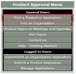
On the menu on the left side of the page, click on Product Approval. Or, click this link to go directly to the search page.
On the Product Approval Menu, click on Find a Product or Application. Note that at this location you can also search for approved organizations such as certification agencies, evaluation entities, quality assurance entities, testing laboratories and validation entities.
Ensure the proper Code Version is shown. The current 2014 Florida Code is based on the 2012 International Codes.
At this point, several options can be searched. You can search for all approvals by a specific product manufacturer or a certain type of building component by searching Category and Subcategory, or if searching for a specific product, by entering the manufacturer’s name and the product name.
Select the option highlighted in red
I hope you find the information contained in the Florida Product Approval system useful. Do you have other needs to find approved products?
There certainly seems to be increased awareness of the potential for damage and injury from tornadoes these days. Recent information published by the Federal Emergency Management Agency (FEMA) and the Federal Alliance for Safe Homes (FLASH) help explain that. This increased awareness has led to a growing interest in tornado shelters for protection of life and property.
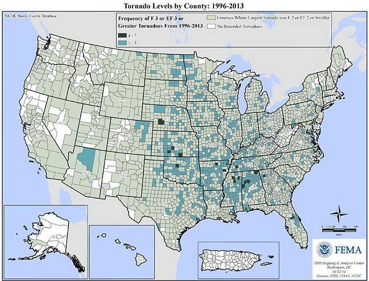
This FEMA graphic shows that most areas of the United States have been affected by a tornado at some point since 1996, and many have been affected by one or more strong tornadoes (EF3 or greater).
Figure 1 – Tornado activity by county: 1996-2013
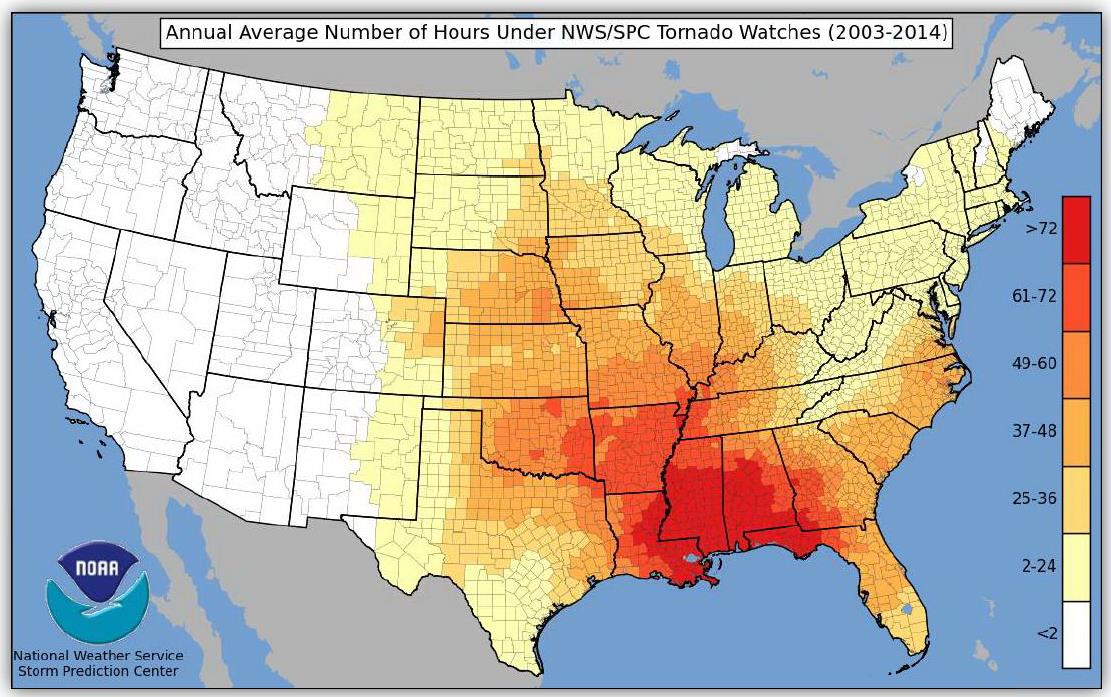
Living in North Texas near the Simpson Strong-Tie manufacturing plant in McKinney, Texas, I know all too well the sinking feeling of hearing the tornado sirens and turning on the TV to find you are under a tornado watch. FLASH recently published a graphic developed by the National Weather Service that shows the large number of U.S. counties that have been under a tornado watch between 2003-2014, and the high number of warnings that some counties experienced.
Figure 2 – Annual average number of hours under NWS/SPC tornado watches (2003-2014)
Other than moving to an area that has fewer tornadoes, one of the best ways to protect your family and at least have more peace of mind during tornado season is to have a tornado shelter or safe room. These structures are designed and tested to resist the highest winds that meteorologists and engineers believe occur at ground level during a tornado and the debris that is contained in tornado winds.
Tornado shelters can be either pre-fabricated and installed by a specialty shelter manufacturer, or can be site-built from a designed plan or pre-engineered plan. A good source for information on pre-fabricated shelters is the National Storm Shelter Association, a self-policing organization that has strict requirements for the design, testing and installation of its members’ shelters.
FEMA publishes a document, P-320, Taking Shelter from the Storm, that provides good information on safe rooms in general, as well as several pre-engineered plans for tornado safe rooms.
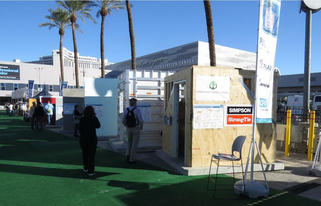
To highlight the different types of safe rooms covered by FEMA P-320, FEMA, FLASH and the Portland Cement Association (PCA) sponsored an exhibit at January’s International Builder’s Show. The exhibit was called the “Home Safe Home Tornado Saferoom Showcase.” It featured six different types of saferooms that builders could incorporate into the homes they build. Simpson Strong-Tie and the American Wood Council collaborated to build a wood frame with steel sheathing safe room meeting the FEMA P-320 plans. Other safe rooms shown at the exhibit included pre-cast concrete and pre-manufactured steel shelters manufactured by NSSA members, and reinforced CMU, ICF cast-in-place concrete and aluminum formed cast-in-place concrete built to FEMA P-320 plans.
Figure 4 – Home Safe Home Tornado Saferoom Showcase
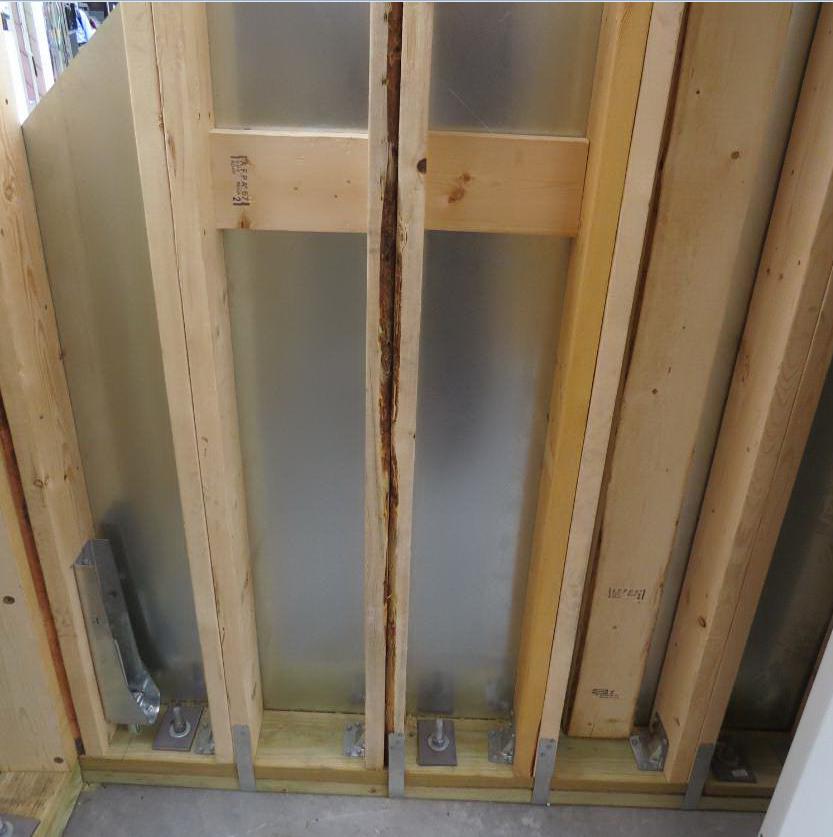
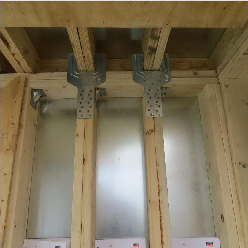
Simpson Strong-Tie staff in McKinney, Texas, constructed the wood frame/steel sheathing safe room in panels and shipped it to the show. It was built from locally sourced lumber, readily available fasteners and connectors and sheets of 16 ga. steel (which we happen to keep here at the factory). It had cut-away sheathing at the corners to show the three layers of sheathing needed. Our message to builders was that this type of shelter would be the easiest for their framers to build on their sites.
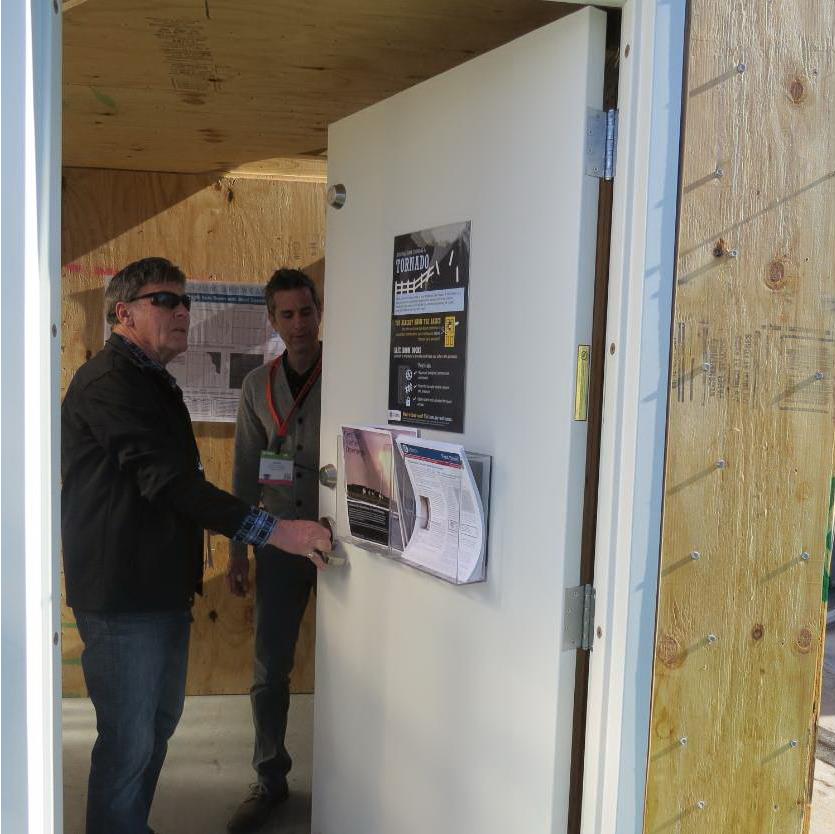
Figure 5: Holdowns and plate anchorageFigure 6: Roof-to-wall connectionsFigure 7: A visitor examines our tested door, a vital component of any shelter. This one was furnished by CECO Doors.
The sponsors of the exhibit took advantage of the variety of safe rooms in one place to film a video series, “Which Tornado Safe Room is Right for You?” The videos are posted at the FLASH StrongHomes channel on YouTube. The series provides comparative information on cast-in-place, concrete block masonry, insulated concrete forms, precast concrete and wood-frame safe rooms, with the goal of helping consumers to better understand their tornado safe room options.
“Today’s marketplace offers an unprecedented range of high-performing, affordable options to save lives and preserve peace of mind for the millions of families in the path of severe weather,” said FLASH President and CEO Leslie Chapman-Henderson. “These videos will help families understand their options for a properly built safe room that will deliver life safety when it counts.”
FLASH released the videos earlier this month as part America’s PrepareAthon!, a grassroots campaign to increase community emergency preparedness and resilience through hazard-specific drills, group discussions and exercises. The overall goal of the program is to get individuals to understand which disasters could happen in their community, know what to do to be safe and mitigate damage from those disasters, take action to increase their preparedness, and go one step farther by participating in resilience planning for their community. Currently, the program focuses on preparing for the disasters of tornadoes, hurricanes, floods, wildfires, earthquakes and winter storms.
Do you know what the risk of disasters is in your community? If you are subject to tornado risk, would you like to build your own safe room, have one built to pre-engineered plans or buy one from a reputable manufacturer? Let us know in the comments below.
This week’s post is a case study featuring a recent restoration job on the central coast of California and how Simpson Strong-Tie® hot-dipped galvanized screws proved to be a better option than traditional spikes.
A pier originally constructed in the 1800s was closed a few years ago as general deterioration caused the structure to become unsafe. As preparation for rebuilding the pier began, one of the major concerns was the attachment of the deck boards to the framing.
Traditionally, the deck boards have been attached with hot-dip galvanized 60d (0.283″ x 6″) spikes. However, spikes have a low withdrawal resistance, are typically predrilled and have a multi-step installation process. In addition, spikes, over time, can begin to back out so that the heads protrude above the top of the deck boards. This creates an unsafe condition for pedestrians and also results in ongoing maintenance work. Here you can see one of the old spikes.
Corroded spike for deck board fastening.
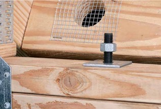
Simpson Strong-Tie provided two options for replacing these spikes: the Strong-Drive® Timber-Hex HDG screw, SDWH27800G, and its stainless-steel counterpart, the Strong-Drive Timber-Hex SS screw, SDWH27800SS. The SDWH27800G screw measures 0.276″ x 8″ and has a hot-dip galvanized coating, conforming to ASTM A153 Class-C. The SDWH27800SS screw measures 0.276″ x 8″ and is made from Type 316 stainless steel. Both of these screws have integral washer, hex-drive heads and are self-drilling. They are not intended to be self-countersinking though, and as a result, installation with the heads below the deck surface requires a shallow dapped hole.
A comparison of the load values was provided to Shoreline Engineering, Inc. engineers Bruce S. Elster, P.E., and Jonathan T. Boynton, P.E., for their review and approval. In addition, Simpson Strong-Tie Fastening Systems/Dealer Sales Representative Darwin Waite expertly conducted on-site demonstrations for numerous decision makers including the contractor and city officials. These demonstrations allowed the contractor and owners to compare the labor costs and finished appearance of the different fastening methods.
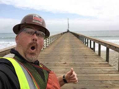
Simpson Strong-Tie Fastening Systems Dealer Sales Representative Darwin Waite takes selfie on the completed dock.
Below is a comparison of the allowable load values* of the potential fasteners. We can see how each of the Simpson Strong-Tie screw options exceeds the spike load values in all load conditions.
Table 1. Comparative allowable properties for hot-dip galvanized spikes (60d), hot-dip galvanized screws (SDWH27600G, SDWH27800G) and stainless steel screws (SDWH27600SS and SDWH27800SS).
*Not to be used for design purposes as footnotes have been left out of this blog post. Table values include wet service factor adjustments.
In the end, the SDWH27800SS stainless-steel screw was specified for the project.
Some might consider a 316 stainless steel screw to be cost prohibitive, but when you factor in the lower cost of installation, the lower maintenance requirements and the actual cost of the fastener, this screw turned out to be the lowest cost alternate. In addition, it provided better withdrawal and lateral load values than the spikes.
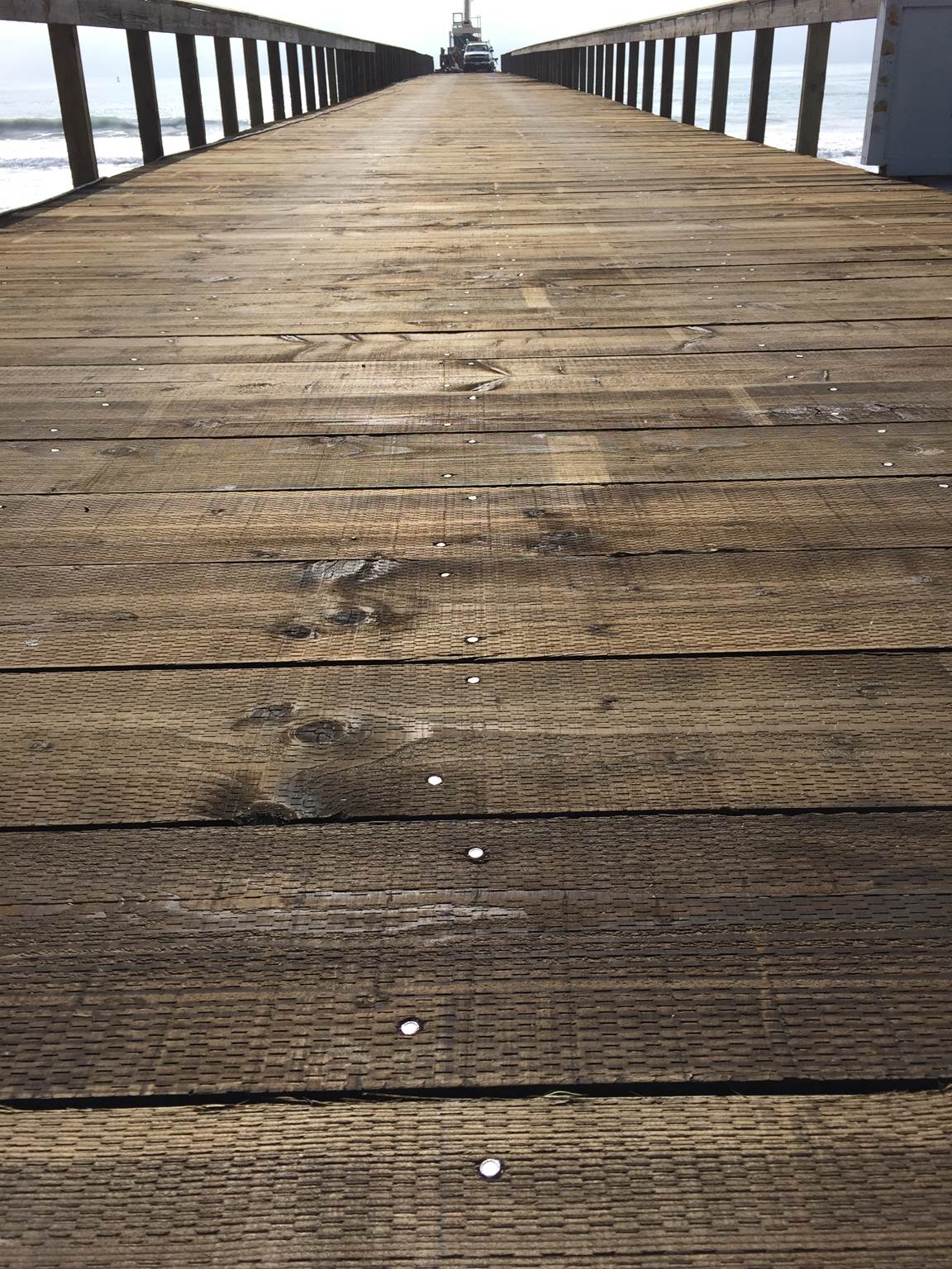
This picture shows the deck fastening in progress. The screws are set and ready for driving with screw-driving tools.
The Strong-Drive Timber-Hex SS screws made it possible to complete the deck restoration on time and on budget. Perhaps just as importantly, the pier looks beautiful and should last for many years to come.
Let us know if the comments below if you have any questions about specifying these fasteners for securing decks, docks, pilings and other heavy-duty, coastal applications.
As always, call our Engineering Department if you have any questions.
Have you used the SDWH27800SS screw for a project? Tell us about in the comments below.
We use cookies on this site to enhance your user experience. By clicking "I AGREE" below, you are giving your consent for us to set cookies. Privacy PolicyI AGREE
Privacy & Cookies Policy
Privacy Overview
This website uses cookies to improve your experience while you navigate through the website. Out of these cookies, the cookies that are categorized as necessary are stored on your browser as they are essential for the working of basic functionalities of the website. We also use third-party cookies that help us analyze and understand how you use this website. These cookies will be stored in your browser only with your consent. You also have the option to opt-out of these cookies. But opting out of some of these cookies may have an effect on your browsing experience.
Necessary cookies are absolutely essential for the website to function properly. This category only includes cookies that ensures basic functionalities and security features of the website. These cookies do not store any personal information.
Any cookies that may not be particularly necessary for the website to function and is used specifically to collect user personal data via analytics, ads, other embedded contents are termed as non-necessary cookies. It is mandatory to procure user consent prior to running these cookies on your website.


 The most cost-effective Simpson Strong-Tie shrinkage compensation device is the RTUD. This device has the smallest number of components and allows the rod unlimited travel through the device. It is ideal at the top level of a rod system run or where small rod diameters are used. Simpson Strong-Tie RTUDs can now accommodate 5/8″ (RTUD5) and ¾” (RTUD6) diameter rods.