A Tale of Two Houses: Design Loads for Metal Plate Connected Wood Trusses

two-houses-trusses

Take two trusses with identical profiles and environmental surroundings, and they should have the same design loads, right? Early in my career, I recall hearing a story about two identical buildings right next to each other that were designed for two different magnitudes of environmental loads. I remember wondering – how do the loads know which building is which?

There used to be a time when it was not uncommon for 5 substantially different wood truss designs to come from 5 different companies – all designing to the exact same spec.  Whereas some differences are always to be expected (manufacturer-specific plate design values and proprietary analogues come to mind), the truss design disparities that used to exist from one company to the next were compounded by variations in something which really shouldn’t vary at all – the application of the specified loads to the truss. Differences in loading can occur whenever there is room for interpretation. In cases where the loading specs for fabricated wood trusses are not very detailed, there is a lot of room for interpretation. And when that happens, everyone knows how many different answers you get when you ask 5 different engineers!

IBC-2012-ASCE

Fortunately, the truss industry has come a long way in this area. In some cases, the codes and standards that govern the loading of structures have improved and helped the cause. But the truss industry also made a concerted effort to minimize these loading differences. Everyone agreed that a truss bid shouldn’t be won based on “less loading,” so they set out to change that. One of the best efforts in accomplishing this was the development of the SBCA Load Guide entitled “Guide to Good Practice for Specifying & Applying Loads to Structural Building Components.” Produced by the Structural Building Component Association (SBCA) in cooperation with the Truss Plate Institute (TPI), the Load Guide was developed with the stated goal of “helping everyone that uses it to more easily understand, define and specify all the loads that should be applied to the design of each structural building component” and “to help assure that all trusses will be designed using a consistent interpretation and application of the code.”

If you are an architect, engineer or a Building Code Official who deals with trusses and you don’t already have the current SBCA Load Guide, I strongly encourage you to check it out (free downloads are available from the SBCA website here.) When fielding questions about loading on trusses, I inevitably refer the inquiring party to the SBCA Load Guide not only for the answer to the question, but for future reference as well. The SBCA Load Guide isn’t just a handy reference to read, it also offers a spreadsheet tool that can be used to calculate loads as well as output the load calculation worksheets. The worksheets can be submitted with the construction documents for plan approval or submitted to the truss manufacturer to be used in the design process.

Worksheet from the SBCA Load Guide

In addition to providing all of the code and standard loading provisions that apply to metal-plate-connected wood trusses, the SBCA Load Guide also presents the truss industry’s consensus positions and interpretations on provisions that are either unclear as to how they apply to trusses or that have resulted in loading inconsistencies in the past. With the many truss-specific examples and applications covered, it leaves very little room, if any, for further interpretation or question as to how the various code provisions should be applied to trusses.

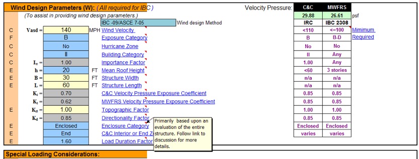
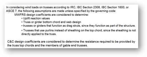
Take wind loads, for example. Wind loading on trusses has been a heavily debated topic over the years, such as whether a truss should be designed for Components & Cladding (C&C), Main Wind Force Resisting System (MWFRS) or both. In fact, wind loading used to be one of the main sources of inconsistencies in truss designs from one company to another.  The truss industry has since established a consensus position on this matter and the SBCA Load Guide presents it as follows:

SBCA-load-guide-consensus

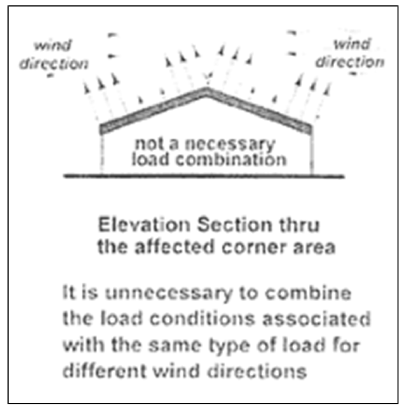
The SBCA Load Guide also pulls information from a variety of resources to help provide more insight into some of the code provisions. For example, in the wind loading section a graphic is reproduced from a Structural Engineers Association of Washington’s handbook (SEAW RSM-03) to clarify the effect of wind directionality on C&C wind pressures for gable/hip roofs, since this consideration is not made clear in ASCE 7.

Graphic from SEAW RSM-03 As Reprinted in the SBCA Load Guide

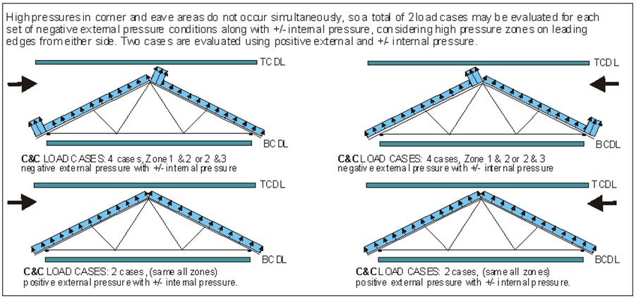
This clarification is further illustrated in the example wind loading diagrams, which show how wind pressures are evaluated when taking the directionality of the wind into account, i.e., by evaluating the pressures separately with the wind from the left and from the right.

Example Wind Loading Diagrams in the SBCA Load Guide

Of course, the SBCA Load Guide is only a guide and is NOT intended to supersede a Building Designer’s design specification. As specified in ANSI/TPI 1, the Building Designer is responsible for providing all applicable design loads to be applied to the trusses:

ANSI-TPI1-text

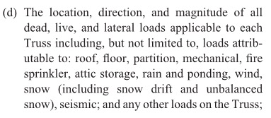
If you are an architect or engineer who specifies detailed loading schedules for truss systems, great!  Your specifications may not need the SBCA Load Guide to ensure that the trusses are accurately loaded as intended in the design of the building. But the SBCA Load Guide still provides a lot of insight as to how the truss industry – and anyone who uses the Load Guide – applies various code provisions to trusses. It might even be an interesting study to see how your specified loads compare to the loading examples in the SBCA Load Guide.

wind-zone-diagram

For everyone else who isn’t well-versed in the application of code provisions to wood trusses, the SBCA Load Guide is an invaluable tool. Building Designers, building code officials, truss technicians and truss Designers can all benefit from the Load Guide. As stated in the SBCA Load Guide, one of the industry’s goals is to achieve a greater level of consensus among the largest audience possible on how to load trusses and other structural building components. The more people who read and use the SBCA Load Guide, the more consistency there will be in the interpretation and application of code provisions pertaining to wood trusses, which will help make projects run smoother and most importantly, improve building safety. At Simpson Strong-Tie, we are big fans of tools that work to do that.

If you’ve had experience using the SBCA Load Guide, we’d love to hear about it – please let us know in the comments below!


Facebook Tips for Structural Engineers

facebook-logoIn our last social media–related blog post, I shared the Top 5 LinkedIn Groups to Follow for Structural Engineers. Following groups on LinkedIn allows you to share content, post or view job openings, network and help establish yourself as a key opinion leader in your industry. But what about critical design questions or help? How do you deal with office dynamics or a difficult client as a structural engineer?

LinkedIn groups may assist with questions like these, but there are other social media platforms that might make it easier to have a more in-depth discussion about issues that you face. While LinkedIn is certainly an important social media platform for professionals such as structural engineers, it is not the largest social media platform. That title goes to the social media giant Facebook. Facebook has the social advantage of engaging more than 1.7 billion active users.

You are probably using Facebook already for personal social networking. However, there are some professional applications for structural engineers on Facebook that you may not have heard about. Here are some Facebook tips for structural engineers that you can use to jumpstart your professional social media arsenal:

Follow Industry-Related Pages

There are a variety of pages that you can follow on Facebook to give you an idea of what is happening in the industry. Following and engaging with pages like Structural Engineering World for design inspiration or Civil + Structural Engineer magazine for project management ideas allows you to have a more professionally focused newsfeed around content that matters to you (while still allowing time for cat memes and Buzzfeed quizzes if you want those, too). One useful page for engineers is the Autodesk Revit page, because it has things like tips on how to share large BIM files.

Join Structural Engineering Groups

Groups are a great way to connect with other Facebook users. As a structural engineer, you are bound to come across an issue that you would like some advice on. By joining a group of other structural engineers, you can ask design questions, questions about calculations and get tips on the best tools for your profession. I would ask your colleagues which groups they recommend joining.

Jumpstart Your Job Search

If you are looking for a new position, I am sure that you already know about LinkedIn. But did you know that there are things like the Career Center App on Facebook pages like the ASCE? The app works for employers looking to hire, too!

Do you have Facebook tips that would you recommend for structural engineer? Let us know in the comments below.

Screw Substitution Calculator Web App

At Simpson Strong-Tie, we do our best to offer tools that make your job easier. One such tool is the Screw Substitution Calculator. It’s a quick and easy-to-use web app created to help you calculate and design using Simpson Strong-Tie fasteners. The app can be used in two ways: (1) to design for a given load and (2) to provide a substitution for NDS fasteners. The app covers design for withdrawal loading, lateral loading and multi-ply connections. For each of these applications you can either design for a load or input the specified NDS fasteners and design an alternate Simpson Strong-Tie screw substitution. The app can generate detailed calculations in a PDF format for any of the selections made, and these calculations can be used for submittals.

Note that although the tool currently does not address corrosion issues, corrosion resistance should be an important consideration before selecting screws for your application.

Below is a screenshot of the Screw Substitution Calculator. As explained above, the app can design for

  1. Withdrawal Loading
  2. Lateral Loading
  3. Multi-Ply Connections

screw-substitution-calculator-main

The input sections for Withdrawal Loading and Lateral Loading (parallel or perpendicular to grain) are similar. A screenshot of Lateral Load Parallel to Grain is shown below.

screw-substitution-calculator-overview

Step 1: General Information In this section, you are requested to select either Fastener Substitution or a Load Entry. If you choose fastener substitution, the app will request in step 4, Fastener Information, that you enter the original fastener design. The fastener substitution calculator will provide Simpson Strong-Tie fastener alternatives for the NDS fasteners. The NDS fasteners covered in this app are bolts, lag screws, wood screws and nails.

If you choose Load Entry, you will notice that the Fastener Information step will disappear and no longer be available for input. Next, select a category from the Design Method section. Available options are Allowable Stress Design (ASD), Load and Resistance Factor Design (LRFD) and Not Specified, if you are not sure of the design method. If the Not Specified option is selected, the design assumes the Load and Resistance Factor Design method, and it further prompts you to answer a few more questions related to Wood Moisture Content, Connection Temperature and End Grain Insertion.

screw-substitution-calculator-general

Step 2: Side Member – In this section, all the information regarding the side member is entered. You can either select a species from the drop-down list or enter the specific gravity of the member manually in the text box. The information button lists all the available specific gravities for wood species combinations from NDS. Then enter the (actual, not nominal) thickness of the side member.

Step 3: Main Member – Similar to step 2, enter all information regarding the main member.

Step 4: Fastener Information – If the Fastener Substitution option is selected in step 1, step 4 will require you to enter information about the NDS fasteners used in the initial design. Enter the fastener type (bolt, lag screw, screw or nail), along with its diameter and length. From the fastener option list you can either select one fastener substitute at a time for each NDS fastener or enter the number of rows and the spacing of NDS-designed fasteners to determine Simpson Strong-Tie fastener options and their spacing requirements.

Step 5: Factors – Enter all factors required for designing the connection. Information pertaining to each factor is provided by clicking the information (i) button. You can use this as a guide for entering the factors.

Once all the input is entered, click on the FASTENER SUBSTITUTION OPTIONS button.

screw-substitution-calculator-options

Clicking FASTENER SUBSTITUTION OPTIONS reveals the available solutions. As a default, the All Types box is checked under Fastener Type, as shown above. You can refine the solutions by unchecking this box and selecting any of the specific fasteners listed – SDWH TIMBER-HEX Screw solutions, for example. On the right, the available solutions are displayed for selection. When a selection is made, the app displays all the input and output for that solution as shown in the screenshot below. You can also create a PDF copy for any of the solutions by clicking on CREATE PDF button.

screw-substitution-calculator-create-pdf

screw-substitution-calculator-create-pdf-2

screw-substitution-calculator-solution

For Multi-Ply Connections, the input for side members and main members is combined into Member Information as shown in the screenshot below. Once the input is entered, click the FASTENER SUBSTITUTION OPTIONS button to display results. Similar to withdrawal loading or lateral loading, you can create a PDF copy of the calculations.

screw-substitution-calculator-steps

Let’s design a 3-ply connection with (3) 2 x 12 DF members for a load of 1,000 plf.

screw-substitution-calculator-steps-2

By clicking FASTENER SUBSTITUTION OPTIONS, you can see all the available Simpson Strong-Tie fastener solutions. You can then select any of the options to generate detailed output. A screenshot of the output, solution and information regarding the selected fastener is displayed below. You can create a PDF copy of the solution by clicking the CREATE PDF button.

screw-substitution-calculator-selection

screw-substitution-calculator-output

screw-substitution-calculator-output-2

Now that you know how easy it is to design using our Screw Substitution Calculator, you can start using this tool for your future projects. We welcome your feedback on the features you find useful as well as on how we could make this program better suit your needs. Let us know in the comments below.


DoD-Compliant CFS Wall Framing Design

Back in the year 2000, the U.S. Department of Defense (DoD) was charged with incorporating antiterrorism protective features into the planning, design and execution of its facilities. The main document developed to meet this requirement is the Unified Facilities Criteria “DoD Minimum Antiterrorism Standards for Buildings” (UFC 4-010-01). The current version was published in October 2013. This document covers what is most commonly referred to as “blast” design.Continue Reading

Treated Lumber and Trusses (and the One Condition Under Which MPC Wood Trusses Shouldn’t Be Used)

What do a chicken house, a water treatment plant and a raised wood floor system all have in common?  Very likely, they all involve preservative-treated lumber.  They’re also all examples of common environments in which preservative-treated, metal-plate- connected (MPC) wood trusses may be specified.

Although trusses are successfully used in a variety of environments that require treated lumber, the first mention of “treated lumber” usually sends up a red flag in a truss design office. While the corrosion protection of truss plates is no different from the corrosion protection of any other steel fastener or hanger that comes in contact with treated lumber, there are a few more considerations that come into play whenever treated lumber is going to be used in a truss application.

Raised Wood Truss Floor System

When fire-retardant-treated lumber or preservative-treated lumber is specified, the first (and easiest) step is to determine whether standard G60 truss plates are acceptable for use with the treated lumber, or whether the chemical treatment requires additional protection of the plates. Recent blog posts have discussed how fasteners are evaluated for corrosion resistance and how the Corrosion Resistance Classifications in our catalog help facilitate selection of hardware and fasteners for different types of treated wood and environmental conditions.  Similar guidelines are also available for determining the proper metal connector plate for different wood treatments. For example, when using the sodium borate–based preservatives and fire retardants, standard G60 galvanized metal connector plates are acceptable. However, ammoniacal/alkaline/amine copper quaternary preservative types require more protection, such as G185, ASTM A153 galvanized- or stainless-steel truss plates. The complete guidelines – Quick Guide for Alternative Preservative Treatments with Metal Connector Plates – are available from the SBCA website.

Truss Plate Corrosion from Treated Lumber

When trusses are used in particularly corrosive environments such as coastal environments or salt storage buildings, the ANSI/TPI 1 standard lists coatings that will provide increased corrosion protection for the plates (see insert, below).

raisedtruss3

The paint coating systems listed in (a) and (b) have been specified in the TPI standard since 1985. These paint coatings, which are applied to the truss plates after the trusses are manufactured, provide alternatives to the double-dipped galvanized or stainless-steel plates used in coastal high hazard areas. In fact, the ANSI/TPI 1 Commentary states that one study – SSPC Report 87-08, Evaluation of Coatings for Metal Connector Plates – concluded that the paint coating systems over standard galvanized plates would be expected to outperform the double-galvanized metal connector plates in field use.

Coal Tar Epoxy-Coated Metal Connector Plate

Once the necessary corrosion protection of the plates has been addressed, the next consideration is the effect of certain lumber treatments on the truss plates’ lateral resistance, or tooth-holding capacity. Fire-retardant treatments generally require strength reductions to be applied to both the lumber and metal connector plate design values. The proprietary treatment manufacturer specifies these design reductions. As soon as the specific treatment is known, the appropriate design reductions can be easily applied by the truss design software and noted on the truss design drawing accordingly.

Besides lumber treatment, there may be other reasons for plate design reductions whenever extra galvanization or special coatings are required. While extra galvanization itself does not necessarily require a reduction in plate values, if the treated lumber’s moisture content (MC) exceeds 19% at the time of truss fabrication, then a 20% reduction to the tooth-holding values is required. The same 20% reduction applies if the environment for the intended end use of the trusses is expected to result in wood moisture content exceeding 19%.

Special Considerations and Red Flags

One corrosive environment that requires special consideration is an enclosed swimming pool. ANSI/TPI 1 requires that trusses be separated from the pool environment by a vapor barrier and be separately ventilated from the pool environment. The exception to this requirement is if the truss plates are made with a stainless steel that is not susceptible to stress corrosion cracking (SCC), i.e., not Types 304 and 316.  Since truss plates made with SCC-resistant stainless steel are not readily available (if at all), a vapor barrier is basically required anytime trusses are used over enclosed swimming pools.

Another important consideration in roof truss applications involving treated lumber is the effect of elevated temperatures. For example, when FRT lumber is going to be used in an environment where high moisture content will exist, an FRT formulated for exterior use may be specified. However, if the exterior FRT has not been tested with elevated temperatures as specified in TPI 1 Section 6.4.9.1, it should not be used in a roof application.

raisedtruss5

But the biggest concern when treated lumber is specified for use in metal-plate-connected wood trusses has nothing to do with corrosion at all.  When a truss Designer gets a job that calls for a preservative treatment for exterior use or an exterior FRT, the very first question will be why is an exterior treatment required/what is the application? Although trusses can be adequately designed for many types of environments, there is one environment that does not mix well with metal-plate- connected wood trusses – exposed exterior applications. The TPI/WTCA Guidelines for Use of Alternative Preservative Treatments with Metal Connector Plates concludes with the following statement:

raisedtruss6

When trusses are exposed to repeated wetting and drying, the corresponding swelling/shrinkage of the wood causes what is commonly referred to as truss plate “back out”.  Since the ability of a truss plate to provide lateral resistance depends on the teeth having adequate embedment into the wood members, any plate “back out” or withdrawal from the lumber due to weathering has an adverse effect on the load capacity of the truss plate.

raisedtruss7
Example of a truss plate that has “backed out”

For this reason, MPC wood trusses must be protected from the elements, from the time they are built and stored through the extent of their life in service. High moisture content that is consistently high can be accounted for; but if the trusses will be exposed to moisture cycling, then it is time to consider something other than a metal-plate-connected wood truss.

What are your experiences with treated lumber and/or corrosive environments and wood trusses? Let us know in the comments section below.

Simpson Strong-Tie® Research and Testing Lab Grand Opening, WSU Pullman

On Thursday, May 5, 2016, Washington State University at Pullman, state dignitaries, construction leaders, WSU construction alumni, PACCAR management, Simpson Strong-Tie management and the press celebrated the grand opening and dedication of the PACCAR Environmental Technology Building (PETB) and the Simpson Strong-Tie Research and Testing Laboratory.

pullman1

The Simpson Strong-Tie team comprised senior leadership, engineering and marketing representatives, led by our CEO, Karen Colonias. In her speech at the opening ceremony, Karen Colonias highlighted the leadership of Simpson Strong-Tie in the engineering and construction materials industry in the U.S. and the world. She emphasized the longstanding partnership between WSU and Simpson Strong-Tie, which spans over twenty years of collaboration in various testing and code development programs, and communicated our excitement at the opportunity to collaborate more closely with WSU’s highly respected engineering department on testing and engineering programs.

Karen Colonias speaking at the Grand Opening

The Paccar Environmental Technology Building (PETB) is 96,000 square feet and houses the Composite Materials and Engineering Center (CMEC) – a highly integrated hub of interdisciplinary research and education in the areas of renewable materials, sustainable design, water quality, and atmospheric research. The shared space in this new building will foster the synergy needed to find new solutions to complex industry problems, such as creating human environments that are at once safe, economical and resilient.

pullman3

The Simpson Strong-Tie® Research and Testing Lab at Washington State University (WSU) is a versatile laboratory designed specifically for the structural testing and prototyping of tall timber buildings, post frame buildings, concrete durability, building repair and retrofit and deck safety, as well as seismic and wind mitigation.

The lab includes a high-capacity reaction 28′ x 46′ concrete floor area with tie-downs, 75-kip capacity at two foot centers through the floor area; a high-capacity wall 28′ long by 2’thick by 18′ tall strong wall that is capable of withstanding a 200-kip reaction in any direction; a central 90-gallon-per-minute hydraulic pump, overhead crate and concrete mixing station. The laboratory is a dynamic space to test new material and design concepts developed in the PETB. This is one of the most visible spaces in the PETB and includes capabilities for mock-ups of new building systems, structural testing and advanced digital manufacturing. Adjoining the lab is an outdoor 32′ by 52′ reaction slab that allows for project display (e.g., Solar Decathlon competition), for developing taller and or larger structures than would be possible on the interior strong floor and for natural weather exposure testing.

pullman4

The lab is part of the Composite Materials and Engineering Center (CMEC), which has been a leader in the development of wood composite materials for more than 65 years. It is an International Code Council–accredited testing facility. The laboratory highlights engineered wood composites and is constructed of cross-laminated timber, glulam, Parallam and, of course, Simpson Strong-Tie® No- Equal connectors.

pullman5

Simpson Strong-Tie and WSU, as Karen Colonias mentioned in her speech, have a longstanding and productive partnership going back over 20 years. The two institutions have worked together in a number of areas, including new product testing, deck safety and seismic risk mitigation.

This year, Simpson Strong-Tie made a significant commitment and established the Simpson Strong-Tie Excellence Fund at the Voiland College of Engineering and Architecture at Washington State University (WSU). The fund provides an annual gift of $100,000 per year over the next eight years to support the new Simpson Strong-Tie® Research and Testing Lab in the PACCAR Environmental Technology Building (PETB). In addition to the lab, the Excellence Fund will support fellowships for professors and graduate students to present research findings, brainstorm about future research and conduct continuing education training.

The faculty of the Composite Materials and Engineering Center is committed to addressing the challenge of restoring and improving the U.S. civil infrastructure and offering an integrated approach linking material discovery, manufacturing innovation, product development, and customized design methodologies that will lead to high-performing, cost-effective solutions for the built environment. The core faculty possess diverse expertise that spans materials science (polymers, wood, cement, steel), durability and corrosion protection, manufacturing and sustainable design. The faculty also has a long history of involvement in developing building codes, standards and product acceptance criteria.

This year, the WSU Voiland College of Engineering and Architecture has more than 1,050 students enrolled in civil engineering, architecture and construction management programs. The alumni from these programs are founders of and senior executives in America’s top construction and design firms. The Wall Street Journal ranked WSU among the 25 universities whose graduates are top-rated by industry recruiters, and the Civil Engineering program is the 13th largest in the nation.

On October 29, 2016, and in line with this partnership, Simpson Strong-Tie is conducting its first annual engineering symposium at Washington State University Pullman. In this symposium, Simpson Strong-Tie engineers will share with the engineering and construction management students the various career opportunities that are available in the industry upon their graduation and introduce them to the exciting history of research and innovation at Simpson Strong-Tie. The Symposium will also include testing in the new lab of our No-Equal structural connectors and solutions.

At Simpson Strong-Tie, we are excited to be strengthening the partnership and increasing the collaboration with WSU faculty and students. We are looking forward to an extended and outstanding relationship that drives research and innovations and introduces new methods to design and construct safer, more resilient, sustainable and economical structures.

Onward and Upward!

Louay Shamroukh, P.E., S.E.

Engineering Manager, Northwestern U.S.

Simpson Strong-Tie® Strong-Wall® Wood Shearwall – The Latest in Our Prefabricated Shearwall Panel Line Part 2

In last week’s blog post, we introduced the Simpson Strong-Tie® Strong-Wall® Wood Shearwall. Let’s now take a step back and understand how we evaluate a prefabricated shear panel to begin with.

First, we start with the International Building Code (IBC) or applicable state or regional building code. We would be directed to ASCE7 to determine wind and seismic design requirements as applicable. In particular, this would entail determination of the seismic design coefficients, including the response modification factor, R, overstrength factor, Ωo, and deflection amplification factor, Cd, for the applicable seismic-force-resisting system. Then back to the IBC for the applicable building material: Chapter 23 covers Wood. Here, we would be referred to AWC’s Special Design Provisions for Wind and Seismic (SDPWS) if we’re designing a lateral-force-resisting system to resist wind and seismic forces using traditional site-built methods.Continue Reading

Simpson Strong-Tie® Strong-Wall® Wood Shearwall – The Latest in Our Prefabricated Shearwall Panel Line Part 1

Some contractors and framers have large hands, which can pose a challenge for them when they’re trying to install the holdown nuts used to attach our Strong-Wall® SB (SWSB) Shearwall product to the foundation. Couple that challenge with the fact that anchorage attachment can only be achieved from the edges of the SWSB panel, and variable site-built framing conditions can limit access depending upon the installation sequence. To alleviate anchorage accessibility issues, we’ve required a gap between the existing adjacent framing and SWSB panel equal to the width of a 2x stud to provide access so the holdown nut can be tightened. Even so, try telling a framer an inch and a half is plenty of room in which to install the nut!Continue Reading

Coating Evaluation for Fasteners – Code-Approved and Alternative Coatings

Who likes red rust? No one I know! How do we avoid corroding of fasteners? Corrosion can be controlled or eliminated by providing a corrosion-resistant base metal or a protective finish or coating that is capable of withstanding the exposure environment. When fasteners get corroded, they not only look bad from outside but can also lose their load capacity. To ensure continued fastener performance, we have to control for corrosion. This blog focuses on evaluating the corrosion resistance of the fasteners.

What does the building code specify?

For use in preservative-treated wood, the IBC-2015 specifies fasteners that are hot-dipped galvanized, stainless steel, silicon bronze or copper. Section 2304.10.5.1 of IBC-2015 (Figure 1) covers fastener and connector requirements for preservative-treated wood (chemically treated wood). While chemically treated wood is part of the corrosion hazard, it is not the whole corrosion hazard. Weather exposure, airborne chemicals and other environmental conditions contribute to the corrosion hazard for metal hardware. In addition, the main issue with the code-referenced requirements for fasteners and connectors used with preservative-treated wood is that not all preservative treatments deliver the same corrosion hazard and not all fasteners can be hot-dip galvanized.

Figure 1: Section 2304.10.5.1 IBC-2015.

What if we want to use an alternative base material or coating for fasteners?

How do we evaluate the corrosion resistance of the alternative material or coating? The codes do not provide test methods to evaluate alternate materials and coatings. However, the International Code Council–Evaluation Service (ICC-ES) developed acceptance criteria to evaluate alternative coatings that are not code recognized for use in different environments. The purpose of acceptance criteria ICC-ES AC257, Acceptance Criteria for Corrosion-Resistant Fasteners and Evaluation of Corrosion Effects of Wood Treatment Chemicals, is twofold: (1) to establish requirements for evaluating the corrosion resistance of fasteners that are exposed to wood-treatment chemicals, weather and salt corrosion in coastal areas; and (2) to evaluate the corrosion effects of wood-treatment chemicals. In this blog post, we will concentrate on the evaluation of corrosion resistance of fasteners. The criteria provide a protocol to evaluate the corrosion resistance of fasteners where hot-dip galvanized fasteners serve as a performance benchmark. The fasteners evaluated by these criteria are nails or screws that are exposed directly to wood-treatment chemicals and that may be exposed to one or more corrosion accelerators like high humidity, elevated temperatures, high moisture or salt exposure.

The fasteners may be evaluated for any of the four exposure conditions:

  1. Exposure Condition 1 with high humidity. This test can be used to evaluate fasteners that could be exposed to high humidity. Typical applications that fall under this category are treated wood in dry-use applications.
  2. Exposure Condition 2 with untreated wood and salt water. This test can be used to evaluate fasteners that are above ground but exposed to coastal salt exposure.
  3. Exposure Condition 3 with chemically treated wood and moisture. This test covers all the general construction applications.
  4. Exposure Condition 4 with chemically treated wood and salt water. Typical applications include coastal construction applications.

Depending on the exposure condition being used for fastener evaluation, the fasteners are installed in wood that could be either chemically treated or untreated. Then the wood and the fasteners are placed in the chamber and artificially exposed to the evaluation environment. Two types of test procedures are to be completed for exposure condition 2 through 4. The purpose of these tests is not to predict the corrosion resistance of the coatings being evaluated, but to compare them to fasteners with the benchmark coating (ASTM A153, Class D) in side-by-side exposure to the accelerated corrosion environment.

ASTM B117 Continuous Salt-Spray Test

ASTM B117 is a continuous salt-spray test. For Exposure Condition 3, distilled water is used instead of salt water. The fasteners are continuously exposed to either moisture or salt spray in this test, and the test is run for about 1,440 hours after which the fasteners are evaluated for corrosion. This is an accelerated corrosion test that exposes the fasteners to a corrosive attack so the corrosion resistance of the coatings can be compared to a benchmark coating (hot-dip galvanized).

ASTM G85, Annex A5

The second test is ASTM G85, Annex A5 which is a cyclic test with alternate wet and dry cycles. The cycles are 1-hour dry-off and 1-hour fog alternatively. This is a cyclic accelerated corrosion test and relates more closely to real long-term exposure. This test is more representative of the actual environment than the continuous salt-spray test.  As in the ASTM B117 test, the fasteners along with the wood are exposed to 1,440 hours, after which the corrosion on the fasteners is evaluated and compared to fasteners with the benchmark coating.

Test Method and Evaluation

The test process involves installing 10 benchmark fasteners along with 10 fasteners for each alternative coating being evaluated. The fasteners are arranged in the wood with a spacing of 12 times the fastener diameter between the fasteners. A kerf cut is provided in the wood between the fasteners to isolate the fasteners as shown in Figure 2 and to ensure elevated moisture content in the wood surrounding the fastener shank. The moisture and retention levels of the wood are measured, and the fasteners are then installed in the chamber as shown in Figure 3 and exposed to the designated condition. The test is run for the period specified, after which the fasteners are removed, cleaned and compared to the benchmark for corrosion evaluation. Figure 4 shows the wood and fastener heads after 1,440 hours (60 days). The heads and shanks of the fasteners are visually graded for corrosion in accordance with ASTM D610. If the alternate coating performs equivalent to or better than the benchmark coating — that is, if the corrosion is no greater than in the benchmark — then the coating has passed the test and can be used as an alternative to the code-approved coating. Figure 5 shows the benchmark and alternative fasteners that are removed from the chamber after 1,440 hours.

As you can see, the alternative coatings have to go through extended and rigorous testing and evaluation as part of the approval process before being specified for any of the fasteners. Some alternative coatings provide even better corrosion resistance than the code recognized options. Sometimes, also, the thickness of these alternative coatings may be smaller than the thick coating required for hot-dip galvanized parts. Some of our coatings, such as the Double-Barrier coating, the Quik Guard® coating and the ASTM B695 Class 55 Mechanically Galvanized have gone through this rigorous testing and have been approved for use in preservative-treated wood in the AC257 Exposure Conditions 1 and 3. In addition, these coatings have been qualified for use with chemical retentions that are typical of AWPA Use Category 4A – General Ground Contact. No salt is found in AC257 Exposure Conditions 1 and 3. Please refer to our Fastener Systems Catalog, C-F-14, pages 13–15 for corrosion recommendations and pages 16–17 for additional information on coatings.

What do you look for specifically in a fastener? Do you have a preference for a certain coating type or color? Let us know in the comments below!

Figure 2: Fasteners with different coatings along with the benchmark, installed in wood and separated by kerf cuts.
Figure 3: Fasteners and wood pieces installed in the chamber.
Figure 4: Snap shot of fasteners in ASTM B117 chamber after 1,440 hours.
Figure 5: Fasteners after 1,440 hours of exposure, removed from the wood, cleaned and compared to benchmark. Coating 1 – Benchmark (Hot- dip Galvanized) and Coating 2 (Alternative coating).

Get There Quicker! How CFS Designer Can Help Speed Up Your Design Process

Did you know that Simpson Strong-Tie is celebrating its 60th birthday this year? We started out with one punch press and the ability to bend light-gauge steel. Then, one Sunday evening in the summer of 1956, Barclay Simpson’s doorbell rang and a request for our first joist hanger led us into the wood connector business. Since then, we’ve continued to grow that business by focusing on our engineering, research and development efforts. Some might say that nowadays we’re an engineering company that also happens to manufacture products, as evidenced by our focus on developing technology tools over the past few years such as web calculators, an updated website and design software. Our focus on technology, however, is really another aspect of our continued commitment to excellence in manufacturing and our application of the tenets of lean manufacturing.

Many of you may already be familiar with the idea of lean manufacturing made famous by Toyota in the early 2000s, along with the principles of continual improvement and respect for people. The concept of continual improvement is based on the idea that you can always make small changes to improve your processes and products. Although they were established in a manufacturing setting, these ideals ring very true for engineering as well; eliminate steps in your design process that don’t add any value to the final project and always be on the lookout for tools or techniques that can speed up your process. Thinking lean isn’t about cutting corners to get your result faster, it’s about mindfully getting rid of the steps that aren’t helping you and finding better ways of doing everyday tasks.

As structural engineers, we can find ourselves working on a variety of projects that lead us to perform repetitive calculations to check different conditions, such as varying parapet heights on the exterior of a building, or we may find ourselves working with an unfamiliar material, such as light-gauge or cold-formed steel (CFS), where we have to take some time away from design to review reference materials such as AISI S200-12 North American Standard for Cold-Formed Steel Framing. Wouldn’t it be great if there were a design tool that could help you complete your light-gauge projects more quickly, in complete compliance with current building codes?

It turns out that Simpson Strong-Tie offers a design tool called CFS Designer™ to help structural engineers improve their project design flow. This program gives engineers the ability to design light-gauge stud and track members with complex beam loading and span conditions according to building code specifications. What does that actually mean, though? Allow me to illustrate with an example of a design project.

Let’s say you’re designing a building and part of your scope is the exterior wall framing, or “skin” of the building. You probably get sent some architectural plans that look something like this:

Figure 1. Sample building elevation with section marks.

The architectural elevations will have wall section marks indicated for different framing situations. Two sample wall sections are shown in Figure 2.

Figure 2. Sample building wall sections.

This building has several different wall section types that include door and window locations, varying parapet heights, diverse finish materials that need to meet different deflection criteria, and different connection points back to the base building. The traditional design calculation that you would need to run for one wall section might begin with a loading diagram similar to Figure 3 below.

Figure 3. Sample calculation of wall stud loading diagram.

Once you have your loading diagram generated, you would need to use reference load tables or a computer analysis program to solve for the axial and moment demands, the reactions at the pinned supports, and the member deflections. 

After you determine the demand loads, you would then need to select a CFS member with sufficient properties, and you may need to iterate a few times to find a solution that meets the load and deflection parameters. After you’ve selected a member with the right width, gauge and steel strength, you’ll need to select an angle clip that can handle the demand loads, as well as fasteners to connect the clip to the CFS stud and to the base building. You would also need to also check the member design to ensure that it complies with bridging or bracing requirements per AISI. Then, after all that, you’d have to repeat the process again for all of the wall section types for your project.

Figure 4. Hmm, CFS design would sure be a lot easier if buildings were just huge windowless boxes…

Just writing out that whole process took some time, and you can imagine that actually running the calculations takes quite a bit longer. I think we can all agree that the design process we’ve outlined is time-consuming, and here’s where using CFS Designer™ to streamline your design process can really help.

CFS Designer is a structural engineering design program that can automate many of the manual steps that are required in the design process. It has an easy-to-understand graphical user interface that allows you to input your project parameters within a variety of design modules from walls and beams, jambs and headers, X-brace walls, shearwalls, floor joists, and roof rafters. The program also enables the design of single stud or track members, built-up box-sections, back-to-back sections, and nested stud or track sections. Figure 5 shows an example of how you would input the same stud we looked at before into the program.

Figure 5. CFS Designer™ user interface for wall stud design.

The program will generate the loading diagrams and complete calculation package for all of these different situations. And along with checking the member properties and deflection limits, CFS Designer will also check bridging and bracing requirements and provide connector solutions for the studs using tested and code-listed Simpson Strong-Tie products. Figure 6 shows an example of the summary output you would receive.

Figure 6. The comprehensive summary output page that covers the complete member design down to the bracing and connection solutions.

One unique part of the output is toward the center of the second page, under the heading “Simpson Strong-Tie Connectors.” This section summarizes the tension and compression loads at each reaction point and then shows a connector solution (such as the SCB45.5) along with the number of screws to the stud and the number of #12 sheet-metal screws to anchor back to the base building. Simpson Strong-Tie has developed and tested a full array of connectors specifically for CFS curtain-wall construction as well as for interior tenant improvement framing, which allows designers to select a connection clip straight out of a catalog without needing to calculate their own designs per the code. It’s just another way we’re helping you to get a little leaner!

speed7

Figure 7. A typical SCB/MSCB bypass framing slide-clip connector showing directional loading along with the table of allowable connector loads.

The last part of the output shown in Figure 6 is titled “Simpson Strong-Tie Wall Stud Bridging Connectors.” It checks the bridging and bracing requirements per AISI S100 and selects a SUBH bridging connector, an innovative bridging solution developed by Simpson Strong-Tie that snaps into place and achieves design loads while only requiring one #10 screw to connect for 75% of applications.

Figure 8. A close-up of the SUBH installed (left) and a wall of studs with bridging installed using the LSUBH clips (right).

You can download a free trial of CFS Designer™ and give it a test drive to see how much time it can save you on a design project. The trial version has almost full functionality, with the exception of not being able to print the output sheets. You can see purchasing information online, and you should always feel free to contact your local Simpson Strong-Tie engineering department with any questions you may have. I hope you are able to take advantage of this great tool to further improve your everyday design processes. We will be sure to keep you updated on our latest technology tools that help speed up the design process.  If you’re using CFS Designer, we’d like to hear your thoughts about the program. Please share them in the comments below.