BRACE FOR IMPACT! Bracing Design for Cold-Formed Steel Studs

While consideration of bracing is important for any structural element, this is especially true for thin, singly symmetric cold-formed steel (CFS) framing members such as wall studs. Without proper consideration of bracing, excessive buckling or even failure could occur. Bracing is required to resist buckling due to axial or out-of-plane lateral loads or a combination of the two.

There are two methods for bracing CFS studs as prescribed by the American Iron and Steel Institute (AISI) Committee on Framing Standards (COFS) S211 “North American Standard for Cold-Formed Steel Framing – Wall Stud Design” Section B1. One is sheathing braced design and the other is steel braced design.

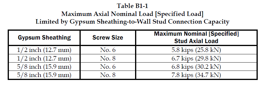
Sheathing braced design has limitations, but it is a cost effective method of bracing studs since sheathing is typically attached to wall studs. This design method is based on an assumption that the sheathing connections to the stud are the bracing points and so it’s limited by the strength of the sheathing fastener to stud connection. Due to this limitation, the Designer has to use a steel braced design for most practical situations. AISI S211 prescribes a maximum nominal stud axial load for gypsum board sheathing with fasteners spaced no more than 12 inches on center. AISI S211 Section B1 and the Commentary discuss the design method and assumptions and demonstrate how to determine the sheathing bracing strength.

CFS Curtain Wall Stud Steel Clip and Bridging Bracing

Sheathing braced design requires that identical sheathing is used on each side of the wall stud, except the new AISI S240 standard Section B1.2.2.3 clarifies that for curtain wall studs it is permissible to have sheathing on one side and discrete bracing for the other flange not spaced further than 8 feet on center. The wall stud is connected to the top and bottom tracks or supporting members to provide lateral and torsional support and the construction drawings should note that the sheathing is a structural element. When the sheathing on either side is not identical, the Designer must assume the weaker of the two sheathings is attached to each side. In addition, the Designer is required to design the wall studs without the sheathing for the load combination 1.2D + (0.5L or 0.2S) + 0.2W as a consideration for construction loads of removed or ineffective sheathing. The Designer should neglect the rotational restraint of the sheathing when determining the wall stud flexural strength and is limited by the AISI S100 Section C5.1 interaction equations for designing a wall stud under combined axial and flexural loading.

Steel braced design may use the design methodology shown in AISI S211 or in AISI Committee on Specifications (COS) S100 “North American Specification for the Design of Cold-Formed Steel Structural Members.”

AISI S211 Table B1-1 Maximum Axial Nominal Load Limited by Gypsum Sheathing-to-Wall Stud Connection Capacity

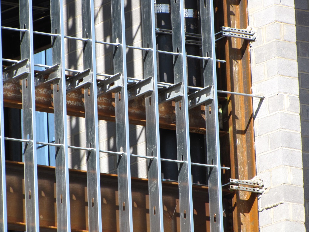
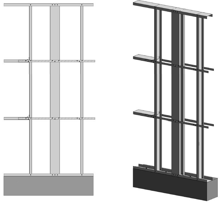
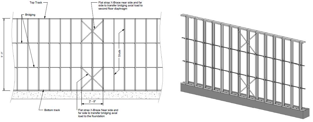
Steel braced design is typically either non-proprietary or proprietary “clip and bridging” bracing, or “flat strap and blocking” bracing periodically spaced along the height of the wall stud.

CFS Wall Stud Steel U-Channel Bridging Bracing
CFS Wall Stud Steel Flat-Strap Bracing and Blocking Bracing

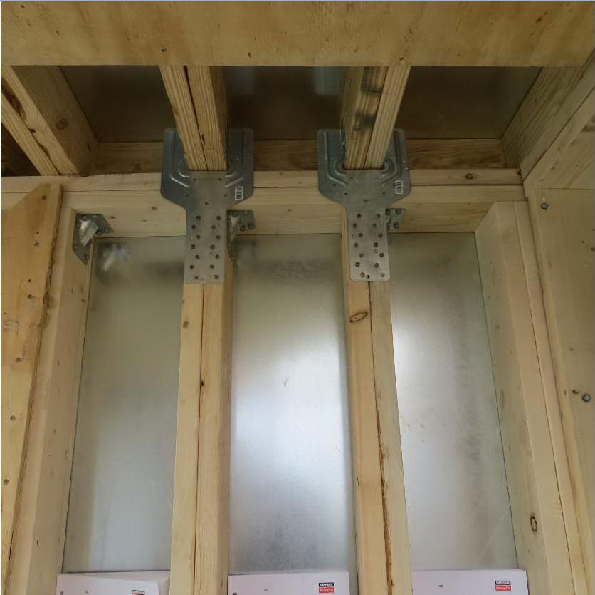
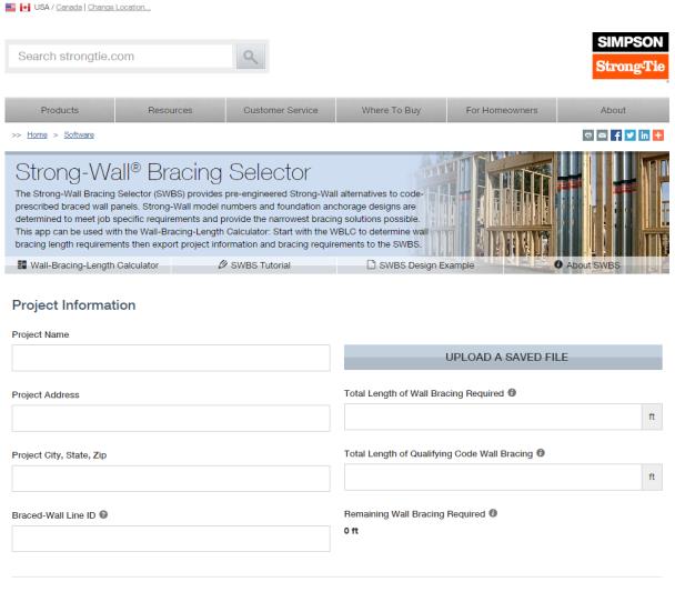
Proprietary wall bracing and wall stud design solutions can expedite design with load and stiffness tables and software as well as offer efficient, tested and code-listed solutions such as Simpson Strong-Tie wall stud bridging connectors.

Simpson Strong-Tie Bridging Connectors

Steel braced design is a more practical bracing method for several reasons. First, during construction, wall studs go unsheathed for many months, but are subjected to significant construction loads.This is especially true for load-bearing, mid-rise structures. Second, some sheathing products, including gypsum wallboard, can be easily damaged and rendered ineffective if subjected to water or moisture. Third, much higher bracing loads can be achieved using mechanical bracing. IBC Section 2211.4 permits Designers to design steel bracing for axially loaded studs using AISI S100 or S211. However, S100-07 requires the brace to be designed to resist not only 1% of the stud nominal axial compressive strength (S100-12 changes this to 1% of the required compressive axial strength), but also requires a certain brace stiffness. S211 requires the Designer to design the bracing for 2% of the stud design compression force, and it does not have a stiffness requirement. . AISI S100 is silent regarding combined loading, but S211 provides guidance. S211 requires that, for combined loading, the Designer designs for the combined brace force determined using S100 Section D3.2.1 for the flexural load in the stud and either S100 or S211 for the axial load. In addition, the bracing force for stud bracing is accumulative as stated by S211 Commentary section B3. As a result, the periodic anchorage of the bracing to the structure such as strongbacks or diagonal strap bracing is required.

CFS Wall Stud Diagonal Strap Steel Bracing Anchorage

Some benefits and challenges of steel clip and bridging bracing include:

  • Proprietary solutions, such as the Simpson Strong-Tie SUBH bridging connector, can significantly reduce installed cost since many situations require only one screw at each connection.
  • Unlike strap bracing, u-channel bracing can be installed from one side of the wall.
  • U-channel bracing does not create build-up that can make drywall finishing more difficult.
  • Extra coordination may be required to ensure that u-channel bridging does not interfere with plumbing and electrical services that run vertically in the stud bay.
  • Bracing for axial loaded studs requires periodic anchorage to the structure, such as using strongbacks or diagonal strap bracing.
  • Bracing of laterally loaded studs does not require periodic anchorage since the system is in equilibrium as torsion in the stud is resisted by bridging (e.g., U-channel) bending.

Some benefits and challenges of steel flat strap and blocking bracing include:

  • May be installed at other locations than stud punchout.
  • Required to be installed on both sides of wall.
  • Bumps out sheathing.
  • Bracing for axial loaded studs requires periodic anchorage to structure, such as using strongbacks or diagonal strap bracing (same load direction in stud flanges).
  • Bracing for laterally loaded studs requires design of periodic blocking or periodic anchorage to the structure (opposite load direction in stud flanges).

There are several good examples Designers may reference when designing CFS wall stud bracing. They include AISI D110 Cold-Formed Steel Framing Design Guide that may be purchased from www.cfsei.org, SEAOC Structural/Seismic Design Manual Volume 2 Example 3 that may be purchased from www.seaoc.org, and the Simpson Strong-Tie wall stud steel bracing design example on page 60 of the C-CFS-15 CFS catalog.

AISI S110 Cold-Formed Steel Framing Design Guide
SEAOC 2012 IBC Structural/Seismic Design Manual Volume 2

Cold-formed steel framing is a versatile construction material, but Designers need to carefully consider the bracing requirements of the AISI specification and wall stud design standard. What cold-formed steel wall bracing challenges have you encountered and what were your solutions?

Florida Product Approvals Made Simple

florida1

This year, the new 5th Edition of the Florida Building Code was released and is now in effect statewide. First printed in 2002, the Florida Building Code was developed as part of Florida’s response to the destruction caused by Hurricane Andrew and other hurricanes in the state.

Another component, which I would like to take a closer look at in today’s post, is a separate Florida Product Approval system designed to be a single source for approval of construction products for manufacturers, Designers and code enforcers. This single system streamlines the previous approach of different procedures for product approval in different jurisdictions. While statewide approval is not required, many jurisdictions, manufacturers and specifiers prefer using the statewide system to the alternative, which is called local product approval. To ensure uniformity of the state system, Florida law compels local jurisdictions to accept state-approved products without requiring further testing and evaluation of other evidence, as long as the product is being used consistent with the conditions of its approval.

The rules of the Florida Product Approval system are in Florida Rule 61G20-3. Here is some basic information about Florida Product Approval.

The Florida Product Approval system is only available for “approval of products and systems, which comprise the building envelope and structural frame, for compliance with the structural requirements of the Florida Building Code.” So users will only find certain types of products approved there. However, if you work in areas where design for wind resistance is required, the Florida system can be a gold mine of information for tested, rated and evaluated products. Not only will you find products like Simpson Strong-Tie connectors with our ICC-ES and IAPMO UES evaluation reports, but thousands of other tested and rated windows, doors, shutters, roof covering materials and other products that don’t typically get evaluation reports from national entities. The specific categories of products covered under the Florida system are exterior doors, impact protective systems, panel walls, roofing, shutters, skylights, structural components and windows.

To protect consumers, a recent law passed in Florida states that a product may not be advertised, sold or marketed as offering protection from hurricanes, windstorms or wind-borne debris unless it has either State Product Approval or local product approval. Selling unapproved products in this way is considered a violation of the Florida Deceptive and Unfair Trade Practices Act.

Once a manufacturer understands the process for achieving a statewide approval, it is not difficult to achieve, but it can be expensive. The manufacturer must apply on the State of Florida Building Code Information System (BCIS) website at www.floridabuilding.org. To prove compliance with the code, the manufacturer must upload either a test report, a product certification from an approved certification entity, an evaluation report from a Florida Professional Engineer or Architect, or an evaluation report from an approved evaluation entity (ICC-ES, IAPMU UES, or Miami-Dade County Product Control). Then, the manufacturer must hire an independent validator to review the application to ensure it complies with the Product Approval Rule and that there are no clerical errors. Finally, once the validation is complete, staff from the Department of Business and Professional Regulation reviews the application. Depending on the method used to indicate code compliance, the application may be approved at that time or it may have to go through additional review by the Florida Building Commission.

Here are several ways to find out if a product is approved.

  1. For Simpson Strong-Tie products, we maintain a page on www.strongtie.com that lists our Florida Product Approvals.
  2. The Florida Department of Business and Professional Regulation maintains a page where users can search Product Approvals by categories such as manufacturer, category of product, product name, or other attributes such as impact resistance or design pressure.
  3. A third-party group we work with has created a website called www.ApprovalZoom.com that lists various product evaluations and product approvals. In addition to listing Florida Product Approvals, they also list ICC-ES evaluation reports, Miami-Dade County Notices of Acceptance, Texas Department of Insurance Approvals, Los Angeles Department of Building Safety Approvals, AAMA certifications and Keystone certifications among others.
florida3
Florida Department of Business and Professional Regulation Product Approvals search

The process for searching for approved products on the Florida BCIS is fairly simple.

  1. Go to www.floridabuilding.org
  2. On the menu on the left side of the page, click on Product Approval. Or, click this link to go directly to the search page.
  3. On the Product Approval Menu, click on Find a Product or Application. Note that at this location you can also search for approved organizations such as certification agencies, evaluation entities, quality assurance entities, testing laboratories and validation entities.
  4. Ensure the proper Code Version is shown. The current 2014 Florida Code is based on the 2012 International Codes.
  5. At this point, several options can be searched. You can search for all approvals by a specific product manufacturer or a certain type of building component by searching Category and Subcategory, or if searching for a specific product, by entering the manufacturer’s name and the product name.
florida2
Select the option highlighted in red

I hope you find the information contained in the Florida Product Approval system useful. Do you have other needs to find approved products?

Truss Repair Information: The Never-Ending Search

Truss repair is one of the most frequently asked about truss topics. Not surprisingly, when we asked for suggested truss topics in a truss blog earlier this year, truss repair information made the list. Because the summer months bring about a peak in new construction – and plenty of truss repairs to go along with it – the beginning of June is the perfect time to visit this topic.

From trusses that get dropped or cut/drilled/notched at the jobsite, to homeowners who want to modify their existing trusses to add a skylight or create attic space to fire-damaged trusses, a multitude of scenarios fall under the broad topic of truss repair. Today’s post focuses on various references and resources that can provide some assistance. But first it helps to break down the broad “truss repair” topic into more manageable-sized categories.

New Construction vs. Recent Construction vs. Old Construction

By far, the easiest type of truss repair is new construction, when the trusses either haven’t been installed yet or are still in the process of being installed. Whether the repair is relatively simple (e.g. a broken web) or a little more complicated (e.g. the trusses need to be stubbed), the beauty of new truss construction is that the truss manufacturer – and truss Designer – can be contacted and help with the repair. The truss Designer can easily open up the truss designs in the truss design software, quickly evaluate the trusses for the appropriate field conditions and issue a repair.

A good reference related to truss repairs for new truss construction is the Building Component Safety Information (BCSI) booklet jointly produced by SBCA and TPI. Section B5 of the BCSI booklet, which is also available as a stand-alone summary sheet, covers Truss Damage, Jobsite Modifications & Installation Errors. This field-guide document describes the steps to take when a truss at the jobsite is damaged, altered or improperly installed, common repair techniques, and the information to provide to the truss manufacturer when a truss is damaged, which will assist in the repair process.

bcsi

The next easiest truss type to repair is recent construction, where the trusses were constructed recently enough that:  a) the truss plates are easy to identify, and b) the truss design drawings may even still be available. In these cases, design professionals other than the original truss Designer may be contacted to repair the trusses. For some types of repairs, the design professional can work off the truss design drawing to design the repair. Other times it might be necessary to model and analyze the truss using structural design software; alternatively, a truss manufacturer can be contacted to model the truss in their truss design software for a fee.

Often, the design professional wants to know the design values for the truss plates that were used to construct the truss. If there are truss design drawings available, they will indicate which truss plates were used in the design, and then the truss plate manufacturer can be contacted for more information. It is also easy to search for the truss plate code reports online (for instance, check icc-es.org). If no truss design drawing is available, there is still a way to identify the truss plates. Currently, there are only five major truss plate manufacturers in the United States, and they are listed on the Truss Plate Institute website. That makes identification of the truss plates used in recently constructed trusses easier because all of the current manufacturers’ plates will have markings that are described in their code reports. (Note that there are also a couple of truss manufacturers in the U.S. that manufacture their own truss plates.)

AS-20 Truss Plate (ESR-2762)

Finally, the most challenging type of trusses for truss repairs are those found in older buildings. Design professionals involved in these types of repair often aren’t sure where to start.  Truss design drawings are often not available, and the act of trying to identify the truss plate manufacturer is challenging at best, unsuccessful at worst. As a point of reference, there were 14 truss plate manufacturers that were TPI members in 1987 (see image below), and only one of those companies is still in the current list of five companies. Therefore, the truss plates found in a truss built around 1987 will be difficult to identify. One option is to contact TPI and see if they can point you in the right direction.

TPI Member Listing from a 1987 Publication
TPI member listing from a 1987 publication

Simple vs. Complex Repairs

Another way to break down truss repairs is to divide them into easy and challenging repairs. People often ask for “standard” truss repair details. Unfortunately, standard details only address the simplest types of repair; and those usually aren’t the types of repair that are asked about. Details simply cannot cover the wide range of truss configurations and every type of repair situation.

Sample Repair Detail for a Simple Repair
Sample repair detail for a simple repair

With the exception of simple repairs, most truss repairs rely heavily on the judgment and experience of the design professional doing the repair. And because there are not entire textbooks devoted to truss repair (that I am aware of, anyway), Designers must pull from a variety of resources, both to learn more about truss repair and to design the repair. For repairs using plywood or OSB gussets, the APA Panel Design Specification is a must-have reference. Some people prefer to use dimension lumber scabs for their repairs, whenever possible, simply because they are more familiar with dimension lumber (and the NDS) than they are with Plywood/OSB or the APA Panel Design Specification.

Next, the fasteners for the repair must be selected and the allowable loads determined. For nail design values, I am a big fan of the American Wood Council’s Connection Calculator, which provides allowable nail shear values for just about any combination of main and side members that you can think of, including OSB and plywood side members – particularly handy for truss repairs. For more complex repairs, and especially repairs involving higher forces, an excellent fastener choice is a structural wood screw such as our Strong-Drive® SDS  or SDW screws. When I worked in the R&D department at Simpson Strong-Tie, a frequently asked question was whether we had double-shear values for our SDS screws. The questions always seemed to come from Designers who wanted them for truss repairs. Fortunately, we do have double-shear values for our SDS screws.. You can find them on page 319 of our Fastening catalog.

Page 319 of the Fastening Systems Catalog (C-F-14)

The Strong-Drive SDW screw was developed after the SDS screw, and while there are currently no double-shear values for the SDW, it is still another good option for repairs.

Fire-Damaged Trusses and Truss Collapses

These situations are in a category by themselves because they go beyond even the most complex repairs involving a major modification to the truss. The biggest difference is that the latter case involves mostly known facts and perhaps some conservative assumptions, whereas damage due to fire or collapse includes many unknowns. Most of the truss Designers I have spoken to about truss damage due to fire or truss collapse often recommend replacement of the trusses rather than repair because it is usually too difficult to quantify the damage to the lumber and/or joints. In fires, there can be “hidden” damage due to the sustained high temperatures, while the truss appears to have no visible damage. Likewise, in a truss collapse, not only may there be too many breaks in the trusses involved in the collapse, but there may also be trusses that suffered severe stresses during the collapse and have damage that is not visible. To attempt a repair in either of these cases often requires an inspection at the jobsite, and the result may still end up being replacement of some or all of the trusses. Therefore, the cost of a full-blown inspection should be weighed against the cost of replacing the trusses.

truss repair information

The Structural Building Components Association website has a page with information pertaining to fire issues. It includes a couple of documents related to fire damage that are worth checking out.

Beyond the Blog: Where to Get More Truss Repair Information

The best bet for getting practical design information related to truss repairs is to keep an eye out for short courses, workshops or seminars. ASCE has hosted a Truss Repair Seminar (Evaluating Damage and Repairing Metal Plate Connected Wood Trusses) in the past and may very well offer something like it again. Virginia Tech recently hosted a short course on Advanced Design Topics in Wood Construction Engineering, which included a section on Wood Truss Repair Design Techniques.

What other references or resources for truss repair do you use?  Are there any upcoming truss repair courses that you know of?  Please let us know in the comments below!

Which Tornado Saferoom is Right for You?

tornado1
Image courtesy of FLASH.

There certainly seems to be increased awareness of the potential for damage and injury from tornadoes these days. Recent information published by the Federal Emergency Management Agency (FEMA) and the Federal Alliance for Safe Homes (FLASH) help explain that. This increased awareness has led to a growing interest in tornado shelters for protection of life and property.

This FEMA graphic shows that most areas of the United States have been affected by a tornado at some point since 1996, and many have been affected by one or more strong tornadoes (EF3 or greater).

Figure 1 - Tornado activity by county: 1996-2013
Figure 1 – Tornado activity by county: 1996-2013

Living in North Texas near the Simpson Strong-Tie manufacturing plant in McKinney, Texas, I know all too well the sinking feeling of hearing the tornado sirens and turning on the TV to find you are under a tornado watch. FLASH recently published a graphic developed by the National Weather Service that shows the large number of U.S. counties that have been under a tornado watch between 2003-2014, and the high number of warnings that some counties experienced.

Figure 2 -  Annual average number of hours under NWS/SPC tornado watches (2003-2014)
Figure 2 – Annual average number of hours under NWS/SPC tornado watches (2003-2014)

Other than moving to an area that has fewer tornadoes, one of the best ways to protect your family and at least have more peace of mind during tornado season is to have a tornado shelter or safe room. These structures are designed and tested to resist the highest winds that meteorologists and engineers believe occur at ground level during a tornado and the debris that is contained in tornado winds.

Tornado shelters can be either pre-fabricated and installed by a specialty shelter manufacturer, or can be site-built from a designed plan or pre-engineered plan. A good source for information on pre-fabricated shelters is the National Storm Shelter Association, a self-policing organization that has strict requirements for the design, testing and installation of its members’ shelters.

FEMA publishes a document, P-320, Taking Shelter from the Storm, that provides good information on safe rooms in general, as well as several pre-engineered plans for tornado safe rooms.

To highlight the different types of safe rooms covered by FEMA P-320, FEMA, FLASH and the Portland Cement Association (PCA) sponsored an exhibit at January’s International Builder’s Show. The exhibit was called the “Home Safe Home Tornado Saferoom Showcase.” It featured six different types of saferooms that builders could incorporate into the homes they build. Simpson Strong-Tie and the American Wood Council collaborated to build a wood frame with steel sheathing safe room meeting the FEMA P-320 plans. Other safe rooms shown at the exhibit included pre-cast concrete and pre-manufactured steel shelters manufactured by NSSA members, and reinforced CMU, ICF cast-in-place concrete and aluminum formed cast-in-place concrete built to FEMA P-320 plans.

Figure 4 - Home Safe Home Tornado Saferoom Showcase
Figure 4 – Home Safe Home Tornado Saferoom Showcase

Simpson Strong-Tie staff in McKinney, Texas, constructed the wood frame/steel sheathing safe room in panels and shipped it to the show. It was built from locally sourced lumber, readily available fasteners and connectors and sheets of 16 ga. steel (which we happen to keep here at the factory). It had cut-away sheathing at the corners to show the three layers of sheathing needed. Our message to builders was that this type of shelter would be the easiest for their framers to build on their sites.

tornado5
Figure 5: Holdowns and plate anchorage
tornado6
Figure 6: Roof-to-wall connections
tornado7
Figure 7: A visitor examines our tested door, a vital component of any shelter. This one was furnished by CECO Doors.

The sponsors of the exhibit took advantage of the variety of safe rooms in one place to film a video series, “Which Tornado Safe Room is Right for You?The videos are posted at the FLASH StrongHomes channel on YouTube. The series provides comparative information on cast-in-place, concrete block masonry, insulated concrete forms, precast concrete and wood-frame safe rooms, with the goal of helping consumers to better understand their tornado safe room options.

“Today’s marketplace offers an unprecedented range of high-performing, affordable options to save lives and preserve peace of mind for the millions of families in the path of severe weather,” said FLASH President and CEO Leslie Chapman-Henderson. “These videos will help families understand their options for a properly built safe room that will deliver life safety when it counts.”

FLASH released the videos earlier this month as part America’s PrepareAthon!, a grassroots campaign to increase community emergency preparedness and resilience through hazard-specific drills, group discussions and exercises. The overall goal of the program is to get individuals to understand which disasters could happen in their community, know what to do to be safe and mitigate damage from those disasters, take action to increase their preparedness, and go one step farther by participating in resilience planning for their community. Currently, the program focuses on preparing for the disasters of tornadoes, hurricanes, floods, wildfires, earthquakes and winter storms.

Do you know what the risk of disasters is in your community? If you are subject to tornado risk, would you like to build your own safe room, have one built to pre-engineered plans or buy one from a reputable manufacturer? Let us know in the comments below.

Pier Decking Fasteners

This week’s post is a case study featuring a recent restoration job on the central coast of California and how Simpson Strong-Tie® hot-dipped galvanized screws proved to be a better option than traditional spikes.

A pier originally constructed in the 1800s was closed a few years ago as general deterioration caused the structure to become unsafe. As preparation for rebuilding the pier began, one of the major concerns was the attachment of the deck boards to the framing.

Traditionally, the deck boards have been attached with hot-dip galvanized 60d (0.283″ x 6″) spikes. However, spikes have a low withdrawal resistance, are typically predrilled and have a multi-step installation process. In addition, spikes, over time, can begin to back out so that the heads protrude above the top of the deck boards. This creates an unsafe condition for pedestrians and also results in ongoing maintenance work. Here you can see one of the old spikes.

Corroded spike for deck board fastening.

Simpson Strong-Tie provided two options for replacing these spikes: the Strong-Drive® Timber-Hex HDG screw, SDWH27800G, and its stainless-steel counterpart, the Strong-Drive Timber-Hex SS screw, SDWH27800SS. The SDWH27800G screw measures 0.276″ x 8″ and has a hot-dip galvanized coating, conforming to ASTM A153 Class-C. The SDWH27800SS screw measures 0.276″ x 8″ and is made from Type 316 stainless steel. Both of these screws have integral washer, hex-drive heads and are self-drilling. They are not intended to be self-countersinking though, and as a result, installation with the heads below the deck surface requires a shallow dapped hole.

A comparison of the load values was provided to Shoreline Engineering, Inc. engineers Bruce S. Elster, P.E., and Jonathan T. Boynton, P.E., for their review and approval. In addition, Simpson Strong-Tie Fastening Systems/Dealer Sales Representative Darwin Waite expertly conducted on-site demonstrations for numerous decision makers including the contractor and city officials. These demonstrations allowed the contractor and owners to compare the labor costs and finished appearance of the different fastening methods.

Simpson Strong-Tie Fastening Systems Dealer Sales Representative Darwin Waite takes selfie on the completed dock.

Below is a comparison of the allowable load values* of the potential fasteners. We can see how each of the Simpson Strong-Tie screw options exceeds the spike load values in all load conditions.

Table 1. Comparative allowable properties for hot-dip galvanized spikes (60d), hot-dip galvanized screws (SDWH27600G, SDWH27800G) and stainless steel screws (SDWH27600SS and SDWH27800SS).

*Not to be used for design purposes as footnotes have been left out of this blog post. Table values include wet service factor adjustments.

In the end, the SDWH27800SS stainless-steel screw was specified for the project.

Some might consider a 316 stainless steel screw to be cost prohibitive, but when you factor in the lower cost of installation, the lower maintenance requirements and the actual cost of the fastener, this screw turned out to be the lowest cost  alternate. In addition, it provided better withdrawal and lateral load values than the spikes.

 This picture shows the deck fastening in progress. The screws are set and ready for driving with screw driving tools.
This picture shows the deck fastening in progress. The screws are set and ready for driving with screw-driving tools.

The Strong-Drive Timber-Hex SS screws made it possible to complete the deck restoration on time and on budget. Perhaps just as importantly, the pier looks beautiful and should last for many years to come.

Let us know if the comments below if you have any questions about specifying these fasteners for securing decks, docks, pilings and other heavy-duty, coastal applications.

pierdeck

As always, call our Engineering Department if you have any questions.

Have you used the SDWH27800SS screw for a project? Tell us about in the comments below.


Strong-Wall Bracing Selector: Bridging the Gap between Engineered Design and Prescriptive Construction

Asking a structural engineer to design wall bracing under the IRC® can be like asking a French pastry chef to bake a cake using Betty Crocker’s Cookbook. The temptation is to toss out the prescriptive IRC recipe and design the house using ASCE 7 loads and the AWC SDPWS shear wall provisions per the IBC®. But if only a portion of the house needs to be engineered, there may be an easier option.

The prescriptive IRC states an IBC engineered design “is permitted for all buildings and structures and parts thereof” but the design must be “compatible with the performance of the conventional framed system.” But how exactly does an IRC braced wall panel perform? The code doesn’t come right out and tell us, but there are two bracing methods that are essentially shear walls masquerading as braced wall panels: Method ABW and Method BV-WSP. Backing into their allowable loads gives us the key to determining equivalence and eliminates the need to develop lateral forces.

But before you can bust out the slide rule and start crunching numbers, you need to figure out how much bracing the prescriptive code requires. We developed our Wall-Bracing-Length Calculator in 2010 to help designers do just that. And last month, we launched our Strong-Wall® Bracing Selector tool to make it easier to specify equivalent solutions for tricky situations.

Strong-Wall Bracing Selector
Wall-Bracing-Length Calculator

You can export the required lengths (and project information) from the Wall-Bracing-Length Calculator directly into the Strong-Wall Bracing Selector or you can manually enter in the required lengths. The selector app will provide a list of Strong-Wall panels that have an equivalent length, evaluate their anchorage loads and return a list of pre-engineered anchor solutions for a variety of foundation types.

If you’re familiar with our Strong-Wall Prescriptive Design Guide (T-SWPDG10), the selector automates this 84-page document in just a few steps. One big upgrade is the ability to select a solution to meet the exact amount of bracing that is required. If you needed 2.8-ft. of wall bracing, you have to round up to the tabulated 4-ft. solutions if you are using the guide, but now you can select a wall solution that is equivalent to 2.8-ft., which might mean a smaller wall width or better anchor options. You also have the ability to save the selector file for later modifications, create a PDF of the job-specific output, or email the PDF directly from the program.

Strong-Wall Prescriptive Design Guide

So next time you get asked to “design” some wall bracing, see if our Wall-Bracing-Length Calculator and Strong-Wall Bracing Selector might save you some time. There is a tutorial and a design example on the Bracing Selector web page, but it’s very easy to use so you may just want to dive right in. I should also point out that the Strong-Wall SB panels have not yet been implemented into the program, but bracing information for them is available on strongtie.com in posted letters for wind (L-L-SWSBWBRCE14), seismic (L-L-SWSBSBRCE14), and seismic with masonry veneer (L-L-SWSBVBRCE14).

Let us know what you think of this new tool in the comments below.


Newest Connector to Satisfy Code

“Does Simpson Strong-Tie write the building code?”

If you work at Simpson Strong-Tie, you get asked this question from time to time when you’re in the field. Over the years, I’ve heard it dozens of times, and because the answer is obviously “no,” it makes you wonder why this belief persists with so many people in the industry. Well, here is my theory: We develop and test products for new code provisions faster than it takes states to adopt the newest codes. So a designer, contractor or building official will often hear about a new Simpson Strong-Tie product or tested application that fills a need before their state building code even defines what that need is. Here are some recent examples:

  • The FWAZ foundation anchor released in 2007 for a 2006 IRC provision that addresses soil pressure loads on basement walls
  • Strong-Drive® SDS screw testing for deck ledgers published in 2008 as alternates to bolts and lags that weren’t prescribed in the IRC until the 2009 edition
  • The DTT2 deck tension tie released in 2009 is used for a 2009 IRC provision that addresses lateral loads on decks
  • BPS ½ -6 bearing plate released in 2011 to address new provisions for shear wall bearing plates in the 2008 SDPWS, which is referenced in the 2009 and 2012 IBC

The latest example is the DTT1Z deck tension tie. Two of our engineers, Randy Shackelford and David Finkenbinder, attended the ICC hearings that resulted in the new 2015 IRC. As soon as a new provision was passed to provide an alternate 750-pound deck lateral load connection (submitted by Washington Assoc. of Building Officials, not Simpson Strong-Tie) we began working on a connector designed to do the job. After several months of R&D, field trials and new tooling, our presses began to stamp out the first production run of the DTT1Z to meet the 2015 IRC provision on December 30, 2014.

DTT1Z Production Run
2015 IRC Detail
2015 IRC Detail

The IRC detail shows an ideal condition where the bottom of the deck joist lines up with the wall plates in the house. We tested this application, but we also wanted to support variations that may come up in the field. The results of this testing appear in our T-C-DECKLAT15 technical bulletin. We also tested the DTT1Z with our Strong-Drive® SDWH Timber-Hex HDG screw and our Titen HD® concrete screw anchor so it can be used in a variety of applications, including prescriptive wall bracing and (very) light shear walls. Many of these applications are covered in the code report (ER130) that was completed just this past week.

2015 IRC Test Setup
Test setup: 2015 IRC detail
Joist Scab Test Setup
Test setup: Blocking attached to side of joist
Joist Blocking Test Setup
Test setup: Blocking running between joists


If you are interested in reading more about the new IRC deck provisions, Randy wrote about them in his Code Corner column in the current Structural Report and David wrote about them in this blog last August.

In case you are wondering how I respond when asked if we write the code, lately I have been answering it with another question: No, but do you know who is responsible for writing the code? My answer to this is “all of us.” If you don’t like what is in there now, work with an association that represents your interests (NCSEA for a lot of us) to submit a code-change proposal, or even submit one yourself. There is no guarantee it will get in, but if it involves a connection, I can guarantee we will get working on it right away!

Let us know if you see a need for a new connection product. If you already have a product idea and would like to work with us to develop it, you can more-formally submit it here.

Don’t Get Washed Away – The Next Wave of Pile Fastener Innovation Has Arrived

For decades, bolts were used for pile construction to ensure a structurally sound connection. While this works on paper, these types of bolted connections are not user friendly to install in the field. The more difficult the connection is to make, the more likely it won’t be done right.

Many pile connections have stringers or beams on each side of the pile. This means the predrilled hole for the bolt must be properly aligned through all of the parts. It takes considerable strength and the skill and care of a craftsman to do this properly, often from the top of a ladder. Given the large size of many piles, the installer also has to tighten the bolt while blind to the back of the assembly. It can take a few minutes per fastener to get the job done right. These conditions have created a great need in the field for a better approach.

Pile connection

After much design and testing, Simpson Strong-Tie has come out with a new faster and safer solution, the SDWH Timber-Hex HDG screw. The screw has a special point, so no predrilling is required. The installation of this fastener takes a matter of seconds, not minutes. This adds up to hours of saved labor costs.

SDWH Timber-Hex HDG screw

More information about the SDWH Timber-Hex HDG screw can be found in the newly released flier F-F-SDWHHDG14, which is on our website.

Loads for these screws are presented two ways. First, there are individual fastener connection values based on screw length and wood side-plate thickness. Second, loads are given for entire assembly connections. These loads are based on the testing of specific fastener layouts. Our assembly testing used piles with one or two stringers attached to each side of the pile. Here is an example of a load table for stringer-to-square pile connection loads.

Connection Loads

Connection assembly layouts are shown in the F-F-SDWHHDG14 flier for square piles, round piles, piles with continuous stringers and piles with stringers that are spliced at the pile. Here is one example below:

SE Blog 4

We are testing additional assemblies as other connections, materials and conditions are identified.

If you have a common condition that you don’t see addressed in the flier, please let us know in the comments below. You can also always call us in the Engineering Department if you have questions.

Why Social Media Matters for Structural Engineers

SE Blog Engineer

We have written posts before about how social media can help you grow your business and how it can make you better at your job. But the main question you may still be asking is “why social media?” Isn’t it just a place to view cat videos or chat with friends?

While you can use social media for personal reasons, it has now become a serious source of professional content that can help make your life as a structural engineer a little easier. Here are some reasons why social media is (still) important for structural engineers:

It Offers Solutions

If you are encountering an issue or problem, there is a strong chance that there are other structural engineers that have faced the same issue. The nice thing is that with social media, you can find those structural engineers a little faster. There are LinkedIn groups for structural engineers, Facebook groups and even blogs that you can turn to if you have a question.

At the Structural Engineering blog, we get questions from structural engineers on a regular basis asking about our calculations or how we have resolved a particular issue. We respond to those questions right away. They also provide us with great insight into the challenges you face day to day.

It Connects You With Other Engineers

We all know that networking is important. Social media just makes it a little easier to start that conversation. Groups on LinkedIn and Facebook are a great way to exchange best practices and ideas. You can also find out about local events with professionals in your area from these groups so that you can network in person.

It Keeps You Informed

Social media is the first place where industry conversations happen now. Whether it is about soft-story retrofit ordinances or truss designer responsibilities, you can find online conversations about structural engineering on a variety of social media platforms.

All in all, social media is a great resource and can supplement the ways that you already enrich your professional career. How has social media helped you with your job? Let us know in the comments below.

Ten Apps for Engineers

Shane Vilasineekul
Guest blogger Shane Vilasineekul, engineering manager

When Simpson Strong-Tie began supporting the use of iPads by employees, it was about the same time my Blackberry contract was expiring, so I decided to go all-in with Apple® and get an iPhone® 4s and an iPad®. Since mobile devices will not replace the heavy lifting required from most engineers’ computers, I wanted to find some apps that complemented my PC use and made me more efficient when I was away from my desk.  After reading reviews and trying out a few, I eventually came up with a list of apps that I recommend. None were developed for engineers, but they are the ones I use most often. Let me know what you think of these or any of your favorites that I missed.

DropBox
DropBox
Google Drive
Google Drive

1. File Sharing Apps: My initial search was for a way to share files between my Apple devices and my PC. Since there is limited space in the free cloud services, I use two: Dropbox (free) for work files and Google Drive (free) for home files. Install the apps on your mobile devices and the software on your computers, create and log into your account, and you are ready to access/modify/share any of these files on any device. Both of these apps are seamlessly integrated into many other apps.

Notability
Notability

2. Organization: I am not the most organized person, so I wanted an app that would help me keep track of my many notes. After trying a few different ones, I settled on Notability ($3). I can take handwritten or typed notes, insert a picture of things like a jobsite photo or a paper handout, draw a sketch, or even insert an audio recording. Best of all, I can organize the notes in folders within the app and also back them up as PDF files to Dropbox.

SlideShark
SlideShark

3.  Presentations: I regularly give PowerPoint presentations, so I started using an app called SlideShark (free) and got hooked. It is simple and remains true to the look of the original PowerPoint program. With the current version, I can access files on my DropBox account, play embedded videos, and use my iPhone as a remote when my iPad is connected to a projector. Although I still present with my trusty laptop most of the time, SlideShark is also great for practicing a presentation on a mobile device anywhere you find yourself with a few spare minutes.

MyScript Calculator
MyScript Calculator

4. Calculator: I was shocked to find that my iPad didn’t have a built-in calculator app. I tried a few free ones, but never really liked them. Then MyScript Calculator (free) came out last year, which solves handwritten equations like the one shown in the icon. Now I look for reasons to use it. It won’t ever replace my TI-85, but I am not sure I want it to.


iBooks
iBooks
iBooks Shelf
iBooks Shelf

5. Reference Guides: I like the idea of having electronic versions of my codes and referenced standards all saved in my iPad. Some of the PDF files I purchased allow me to save them in iBooks (free); others shown in the screenshot are just covers. On a side note, ICC has all of their codes online, broken into sections (as opposed to a single PDF). It’s great for sending links of specific code language to people that don’t own the code.

GoodReader
GoodReader

6. Editor Apps: There are tons of PDF editing apps out there. I asked around to see what other engineers use and decided on GoodReader ($5). I have been pretty happy with it, mostly using it to mark up PDF files I am reviewing.


PhotoSynth
PhotoSynth

7. Photos: When out on a jobsite, there is no better way to capture information than with a picture. But when everything can’t fit inside the viewfinder, PhotoSynth (free) is a great tool to capture the surroundings. Immersive 360° images  can be posted online, shared, or viewed within the app. Here are links to a couple of mine: Hurricane Sandy, Columbus Test Lab.

SnapSeed
SnapSeed

8. Photo Editing: While on the topic of photos, I use Snapseed (free) whenever I need to edit them. It is simple and intuitive, but powerful enough to get the job done.


Scanner Pro
Scanner Pro

9. Scanner Pro ($3) turns your camera into a scanner. Take a picture of a paper document, then locate the corners of the paper within the app and turn it into a PDF file that scales and stretches it to look like a scan instead of a snapshot.


Paper
Paper
Sketchbook Express
Sketchbook Express

10. Sketch Apps: My favorite apps for sketching a new connector idea, illustrating a concept or just doodling, are Paper (free) and SketchBook Express (free). Paper is more free-form and natural, while SketchBook has more tools and provides more precise control. They are free, so give them both a try.

*Apple, the Apple logo, iPhone and iPad are trademarks of Apple Inc., registered in the U.S. and other countries.*