This week’s blog was written by David Finkenbinder, P.E., who is a regional engineer working out of the Simpson Strong-Tie Ohio branch which services 24 states through the Northeast, Midwest, and Mid-Atlantic. He graduated from Penn State with a B.S. in Agricultural and Biological Engineering in 2004 and earned his M.S. in Civil Engineering with a focus on Structural Engineering from Virginia Tech in 2007. His master’s thesis investigated the splitting strength of bolted connections in solid-sawn lumber and structural composite lumber. Since joining Simpson Strong-Tie in 2007, David has shown a passion for deck safety and has served on committees developing prescriptive information and building code provisions for decks. Here is David’s post.
“Decks cause more injuries and loss of life than any other part of the home structure. Except for hurricanes and tornadoes, more injuries may be connected to deck failures than all other wood building components and loading cases combined.”
This quote, taken from Washington State University’s magazine article Making Decks Safer, underscores the critical importance of proper deck design, construction, and maintenance. An engineer who is encountering their first deck may be surprised that the deck design resources available are not as plentiful as he/she might have expected. The following resources can be helpful start:
For decks built to the IRC, the book Deck Construction Based on the 2009 International Residential Code provides a review of applicable code provisions and related commentary. The book gives background on important durability considerations such as flashing at points where the deck connects to an adjacent structure. The book also briefly discusses variations with IBC provisions, which can be significant for examples such as minimum guard height and live loads.
The American Wood Council (AWC) has several tools available in addition to using the NDS for wood member and connection design. Calculators for evaluating simple span joists and single fastener connections are available in both web-based and mobile app format. Technical Report 12, which was the topic of our May blog post, provides the ability to design connections with a gap between members, or with members having a hollow cross section. AWC’s DCA6 – Prescriptive Residential Wood Deck Construction Guide presents information for common deck details and a commentary covering important considerations for alternate designs. While the guide is helpful, please note that it is limited in scope to single level residential decks and does not address wind or seismic design.
Researchers at Virginia Tech and Washington State University conducted laboratory testing and published information to help in several common topics needing attention. An article in the May 2008 issue of Structure Magazine featured test performance of ledger-to-band joist connections using bolts or lag screws – this information has since been adopted into the IRC.
For lateral design there has been some uncertainty regarding lateral loads that can be generated by occupants, and if the magnitude of such is significant in comparison with wind and seismic forces calculated from ASCE 7. Tests were conducted of occupants performing several types of movement on a deck floor configuration. Separate articles summarizing results for each load type were published in the Summer 2013 issue of Wood Design Focus, along with a fourth article on the lateral performance of IRC ledger attachments (online copies of the articles courtesy of Professional Deck Builder magazine: Wind Loads; Seismic Loads; Occupant Loads).
This January I wrote a blog post, Spanning the Gap, which discussed two methods for establishing allowable loads for fasteners installed through gypsum board – testing or calculations using American Wood Council’sTechnical Report 12. AWC recently published a new version of TR12 and this week’s guest blogger, Lori Koch, Project engineer with AWC, authored this post to explain some of the new features of TR12.
Lori Koch graduated from Penn State University with a BS in Civil Engineering, and from Clemson University with an MS in Civil Engineering. After graduating from Clemson, Lori worked as a forensic structural engineer doing field inspections, job site monitoring for compliance with project specifications and structural analysis on existing structures. She then enrolled at Virginia Tech pursuing a Master of Forestry degree in the Department of Wood Science and Forest Products (now called the Department of Sustainable Biomaterials). Her research at Virginia Tech involved connections for fall-protection harnesses for residential roofers and construction workers. After graduation in 2012, Lori started working with the American Wood Council as a Project Engineer. Her work at the AWC ranges from assisting in codes and standards development, answering HelpDesk inquiries, outreach and educational opportunities and just about anything that can help promote the use of wood in safe and sustainable buildings.
The American Wood Council’s Technical Report 12 – General Dowel Equations for Calculating Lateral Connection Values (TR12) was recently updated. TR12 provides background and derivation of the mechanics-based approach for calculating lateral connection capacity used in the National Design Specification® (NDS®) for Wood Construction for connections using dowel-type fasteners including bolts, lag screws, wood screws, nails, spikes, and drift pins. It also provides additional flexibility and broader applicability to the NDS provisions, including design provisions for connections with gaps. The 2014 version of TR12 provides new information on design of wood members attached to hollow members and design of driven-fasteners with tapered tips.
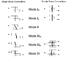
The previous version of TR12 presented mechanics-based derivations of lateral yield equations for solid members joined with a dowel-type fastener (Figure 1). Following the same approach, yield equations were derived for connections between solid members and members with hollow cross sections (Figure 2). These new equations are presented in tabular form for connections with a solid main member and hollow side member(s) and connections with a hollow main member and solid side member(s). Derivations of these yield equations are also presented in the report.
Figure 1. Yield Modes for members of solid cross section.Figure 2. Yield Modes for members of solid and hollow cross section.
The 2012 NDS section 11.3.5.2 adopted new provisions for driven fasteners with tapered tips. For a driven fastener where the penetration length includes the length of the tapered tip, the dowel bearing length is taken as the length of penetration minus one half of the length of the tip. TR12 provides derivation of yield equations that account for the full penetration length, including the reduced bearing capacity at the tip. Design values using these yield equations are then compared against the simplified approach in the 2012 NDS Results of that comparison are contained in a new example included in TR12, and show excellent agreement between the simplified and exact models.
There are many applications where TR12 can be used by engineers to expand upon the NDS connection provisions. Previous versions of TR12 have provided designers with the ability to design connections with a gap between the members. The new provisions in TR12 can be used to calculate the connection capacity of a hollow steel tube connected to solid lumber, where the tube can be either the main member or side member(s).
The recent updates to TR12 will provide increased flexibility for designers while providing additional background information on the derivation of the connection equations. The report is available for free download on the AWC’s webpage at http://www.awc.org/publications/TR/index.php.
What are your thoughts on these updates to TR12? Let us know in the comments below.
Designing wood structures properly requires a broad knowledge base of a variety of materials and how they go together. However, it can often be difficult to find educational opportunities for designers to learn about wood design or keep up with new technologies on wood construction.
Fortunately, there are some unique chances this summer to increase your knowledge about wood as a construction material.
There is a short course titled Advanced Design Topics in Wood Construction Engineering, being held May 21 and 22 at Virginia Tech University in Blacksburg, VA. It is intended for designers, inspection professionals and builders that want to expand their general knowledge of wood as a building material and their knowledge of building design beyond the introductory level. The agenda includes sessions on Decay Processes, Design for Durability, and Insects that Attack Wood; Wood Shrinkage Issues in Construction; Lumber Grading Methods and Design Values; Design of Built-Up Beams and Columns; Glulam Beam Design; Evaluating Structural Capacity of Fire-Exposed Timber Beams and Columns; Multiple-Bolt Wood Connection Design; Basics of Diaphragm and Shear Wall Design; Post-Frame Building Design and Diaphragm/ Shear Wall Tests; Creep of Solid-Sawn Joists, I-Joists, and Floor Trusses; Design Considerations for Preventing Flat Roof Failures from Gravity Loads or Sustained Live Loads; Wood Truss Design Responsibilities; Wood Truss Repair Design Techniques; Permanent Truss Bracing Design Basics; and Lateral Design of Decks.
You can find more information about the Virginia Tech Short Course here. Web registration ended May 14, 2014; you can register by calling the Conference Registrar (540) 231–5182 up to the first day of the course.
If you feel like travelling, the World Conference on Timber Engineering (WCTE) will be held in Quebec City on August 10-14. WCTE is an international biannual event focusing on timber engineering, engineered wood products and design of timber structures. The conference theme is “Renaissance in Timber Construction.” Information on the conference can be found here.
But you don’t have to necessarily travel far to get quality training on wood design.
WoodWorks is a cooperative venture of major North American wood associations, research organizations and government agencies that aim to encourage and assist architects, engineers and others in the use of wood in non-residential and multi-family buildings. WoodWorks deliver knowledge to designers in three main ways: webinars, short 2-3 hour seminars and Wood Solutions Fairs. Upcoming webinars include Mixed Use Podium Design, Changes to Wood Design Standards and Healthy Buildings. Seminars scheduled for June focus on Cross Laminated Timber in California, Pennsylvania, Texas, and Washington. Finally, Wood Solutions Fairs are excellent all-day events where attendees can choose from more than 15 classes in six sessions throughout the day. The Fairs also include exhibits to allow for networking with building product manufacturers. Upcoming Wood Solutions Fairs are May 22 in Chicago, August 27 in Washington, DC, October 23 in Portland, Oregon, and November 12 in Arlington, Texas. Here is a full schedule of WoodWorks events.
If you just can’t get out of the office, or you don’t like to travel, there are still ways to keep up with the wood industry. Several groups offer webinars or self-study classes on various subjects.
WoodWorks, mentioned above, is a good resource. The American Wood Council (AWC) is the voice of North American traditional and engineered wood products, representing more than 75% of the industry. AWC’s engineers, technologists, scientists, and building code experts develop state-of-the-art engineering data, technology, and standards on structural wood products for use by design professionals, building officials, and wood products manufacturers to assure the safe and efficient design and use of wood structural components. AWC also provides technical, legal, and economic information about wood design, green building and manufacturing environmental regulations advocating for balanced government policies that sustain the wood products industry. AWC has begun offering regular webinars on various subjects with complimentary registration. Upcoming webinars include the AWC Prescriptive Residential Wood Deck Construction Guide on May 22, AWC Web-based Calculators and Other Resources on June 24, and Prescriptive and Engineering Design per the 2012 WFCM will be offered some time in the fall. Also, AWC has a comprehensive library of e-courses on their website as well as a helpdesk via email, info@awc.org.
In addition, the International Code Council offers a variety of online training classes as part of their ICC Campus Online. Most have a nominal fee, but several are available free of charge. They have a Catalog of Classes on their website.
And finally, don’t forget about resources available from Simpson Strong-Tie. These resources range from full and half-day workshops offered at various locations throughout the country to online courses you can take from the comfort of your own office. Many of these courses come with CEU credits and some also offer AIA credits. And if you would like a personal visit, such as a lunch-and-learn, contact your local sales rep, or one of our regional offices and ask to speak with the training manager.
Do you know of any other good events coming up? Keep the conversation going.
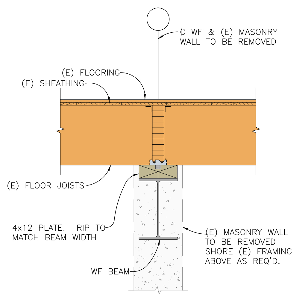
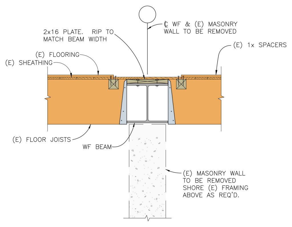
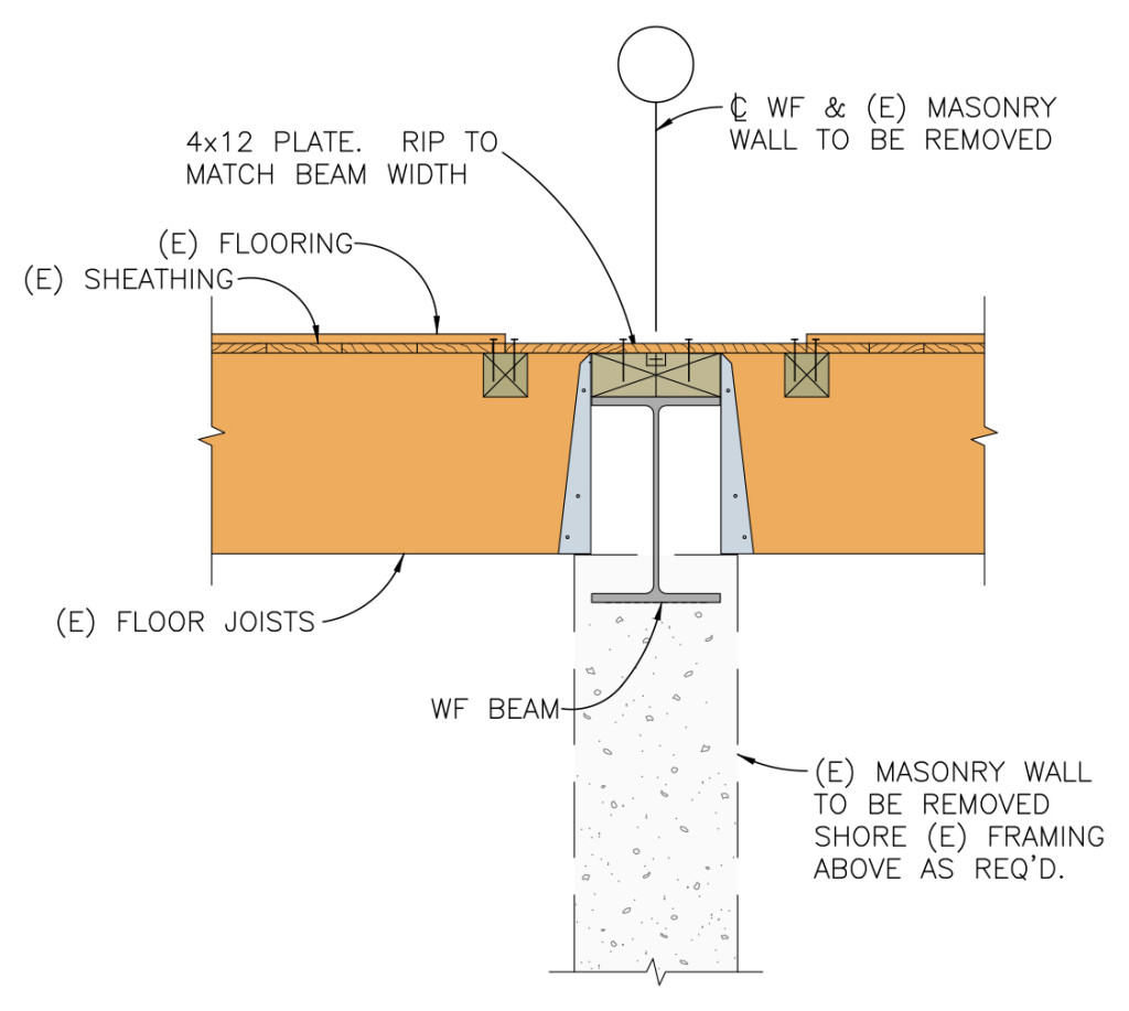
How did that beam get so big? This is what I had to ask myself when I finished sizing and detailing a steel beam that was supposed to fit within the floor joist depth for a flush ceiling. We were removing an unreinforced masonry bearing wall and installing a new wide flange beam to support the existing floor joists as part of a seismic retrofit and remodel. Since the floor joists spliced over the existing bearing wall, it would have been much easier to simply install a new beam below the joists.
Beam below joists
The architect did not want the beam installed below the framing, as it would protrude too much. Steel design offers multiple wide flange sections that will work for a given loading. For this particular design, I could use a W24x55, a W16x67 or a W14x90. Each has about the same strength (section modulus, Sxx) and stiffness (moment of inertia, Ixx). Without constraints, you would select the lightest section that works. Space limitations that require a shallower beam result in increased beam weight (and cost).
Beam flush with ceilingFraming hung off beam
I proposed two solutions for installing the beam in the floor space and hanging the joists off a nailer. One option allowed the steel beam to extend below the floor joists, while the other used a heavier, shallower beam to fit within the space. The owner wanted a flat ceiling and did not mind the added cost for the beam, which weighed about 60% more than the optimum beam size.
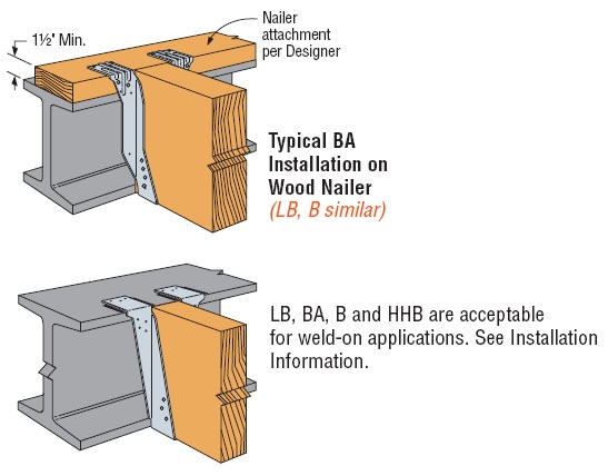
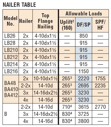
Regardless of space constraints for the design of a steel beam, structural engineers need to specify an appropriate hanger for connecting to the steel beam. Simpson Strong-Tie has many suitable top flange hangers. Most common are hangers that are attached to a wood nailer. Many top flange hangers may also be welded to the beam. Not every nailer solution is rated for uplift, so choose a hanger that meets your requirements. Uplift for welded hangers is addressed in a Simpson Strong-Tie® technical bulletin, T-WELDUPLFT.
Launched in January 2013, the Simpson Strong-Tie® Strong Frame® special moment frame (SMF) has been successfully used on many projects around the country. We’ve explored several aspects of the frame in previous blog posts, including beam bracing requirements, soft story retrofits, and the San Francisco retrofit ordinance. If you have specified the Strong Frame SMF on your project, here are a few helpful items to review during your structural observations at installation.
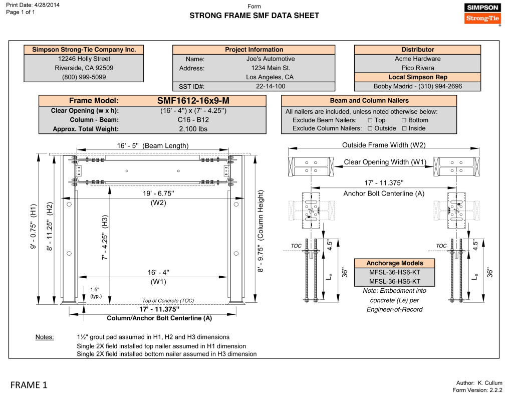
When the special moment frame is ordered, Simpson Strong-Tie sends the contractor a frame verification sheet to verify the dimensions (Figure 1). It is not uncommon for minor adjustments to be made to accommodate specific field conditions. We recommend the framer follow up with the Designer to ensure the needed modifications do not alter the design of the frame based on deflection or strength stand point limitation(s). Once we receive the signed verification, we begin fabricating the frame. The accompanying concrete anchors are usually shipped before the frame so they can be placed ahead of time.
It all starts with the concrete! The majority of misinstallation issues involve anchorage placement. Anchors not placed correctly can alter the frame that’s already been ordered, affecting lead times or requiring retrofit to properly transfer the frame forces into the concrete. Contact your local Simpson Strong-Tie sales rep to help with any questions.
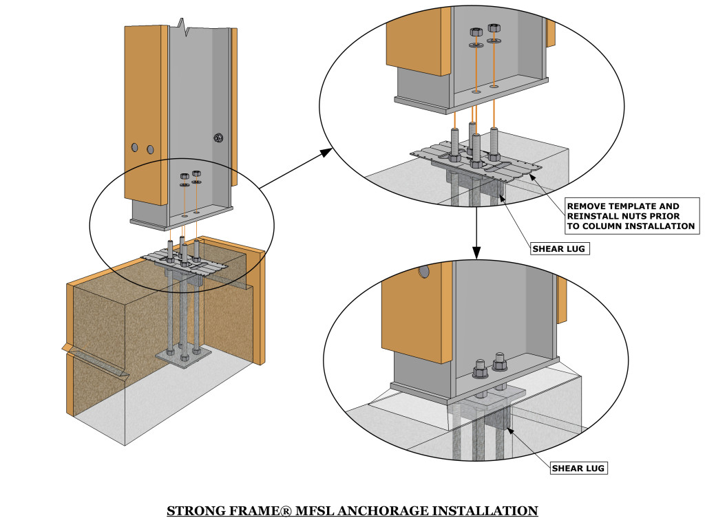
Placement of the Moment Frame Shear Lug (MFSL) is critical to ensure proper transfer of shear forces into the foundation. If you are visiting the jobsite prior to concrete placement, take a look at the orientation of the MFSL. The MFSL contains back-to-back structural angles placed at the top of concrete to transfer the shear component of the Strong Frame SMF forces into the concrete. Figure 2 shows the proper placement of the MFSL and template in relationship to the direction of the column.
Figure 2: Proper Installation of MFSL in relationship to the Column
The template has a similar appearance to the shape and size of the column base plate, which sometimes leads to the tendency to orient the template 90 degrees from its proper installation, as shown in Figure 3. The template has two half circles at the center of the anchor bolts for proper measurement (center-to-center of columns) by the contractor, as shown in Figure 4.
Figure 3: Improper orientation of MFSL TemplateFigure 4: Top View of MFSL Template
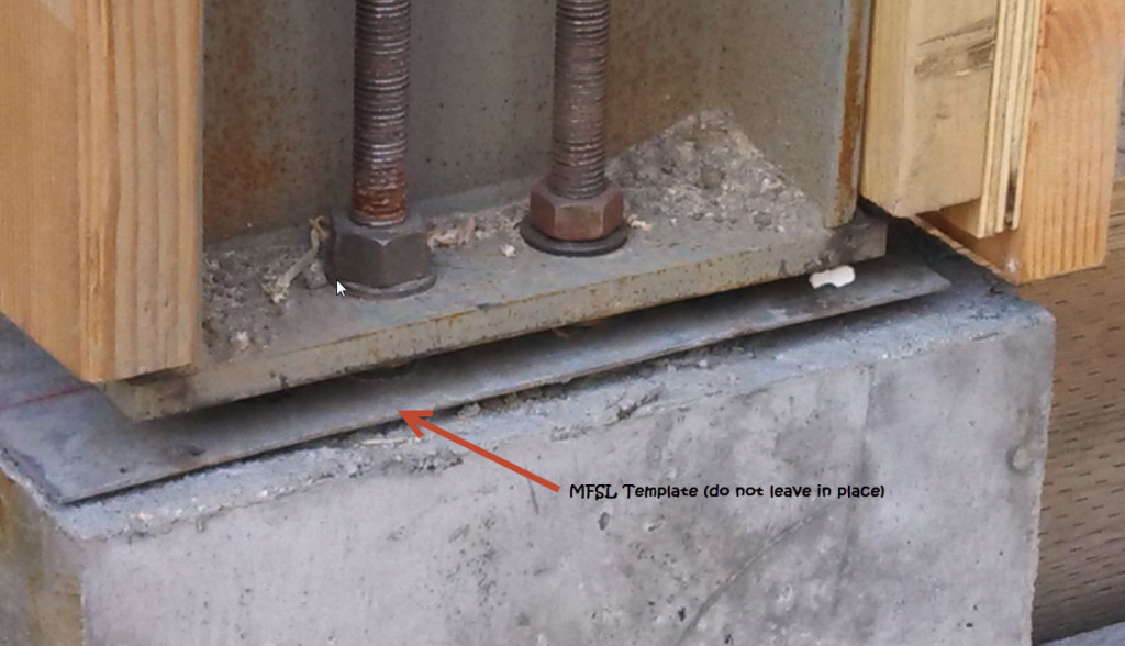
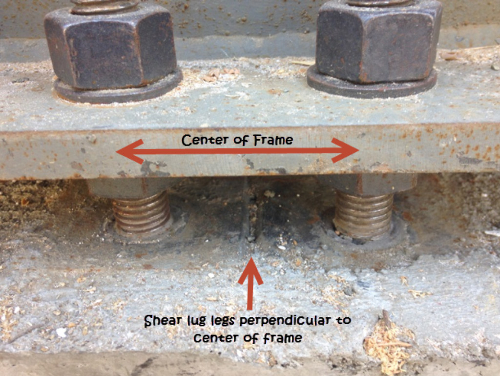
The templates are temporary and intended to be removed prior to frame installation (unlike the case in Figure 3). So placement of the shear lugs is more critical to verify than the direction of the template, since the contractor may remove the template and reinstall it in an alternate orientation. The vertical legs of the two structural angles should intersect the column’s weak axis (perpendicular to center of frame) as shown in Figure 5, and should not be placed parallel to the strong axis.
Figure 5: Proper Orientation of MFSL
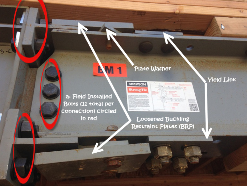
According to ASTM A325, installation requires 11 bolts snug tight at each beam-column connection (labeled “a” in Figure 6), and the column needs to be attached to the four anchor bolts into the base of each column. Many components of the Strong Frame SMF are factory-installed, including the Yield-LinkTM structural fuses, Buckling Restraint Plates (BRP), and nailers. The Yield-Link fuses and BRP should not be disassembled. Figure 6 illustrates an instance where the BRP was loosened during erection. The BRP prevents the Yield-Link fuses from buckling when the frame is subjected to compression forces. Contact Simpson Strong-Tie if you encounter this in the field.
Figure 6: Beam-Column Connection
The wood nailers may be replaced in kind. It is important to note that attachment of the nailers may not utilize all available bolt holes on the column and beam. Various holes are left unused for flexibility with installation of utilities and electrical wiring.
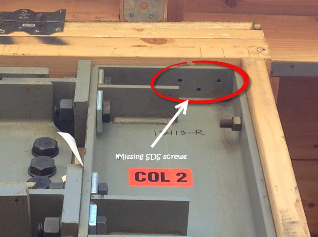
Lastly, often overlooked at installation are the required SDS screws through the column cap plate into the framing above (Figure 7). The SDS screws are included with the installation kit. They are required for bracing of the column on both faces of the column.
Figure 7: Missing SDS screws for Column Bracing
How is the Strong Frame special moment frame working for you? Please let us know in the comments!
I am pleased to introduce you to one of our newest members of the Simpson Strong-Tie team, Minara El-Rahman. She is our Social Media Manager here at Simpson Strong-Tie. Minara has extensive experience with digital/mobile marketing, social media marketing, engaging with online influencers and blogging. As structural engineers use online resources more and more, she will be contributing to the Structural Engineering blog to help you navigate using them.
The last time we wrote about social media, we gave tips on how structural engineers can use social media to be better at their jobs. But we also believe that you can use social media to grow your business. The more touch points that you can have with your existing and potential clients, the better chance you have at forging a relationship with them. That’s what social media is all about, it is about engaging and fostering a relationship with others: whether it is with an individual, company, brand or your old college buddies.Continue Reading
Designing my first building was truly a learning experience. I remember one event in particular when I determined the required thickness for a steel column base plate. That day I wrote “1.5-inch thk. min.” on my calc pad and months later while out walking the job, I got to see that 1.5-inch thick plate in the flesh. Let me tell you, it was much thicker and heavier in-person than on my calc pad. This eye-opening experience – the realization that what you’re designing isn’t just a word or a number, but rather a physical object with width, height, length and weight – is something every structural engineer goes through early in their career. Designing something on paper doesn’t convey those physical properties very well.Continue Reading
Let’s be honest, going to school and majoring in structural engineering or architecture is not easy. Just look at Paul McEntee’s post about his experience with his semester long course in Statics at 7:00 AM complete with Friday pop quizzes for proof in our post about Statics and Testing. While these majors may be a challenge, we know that the degree at the end is well worth the effort. Our industry is a great one to work in and not only do we make other people’s lives better, but we also can save lives too. Which is exactly why Simpson Strong-Tie has developed a structural engineering/architecture scholarship program. Continue Reading
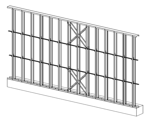
The number of midrise structures constructed using light-frame cold-formed steel (CFS) certainly seems to be increasing each year. As with any material, there are benefits and challenges, especially in areas of moderate to high seismic risk. This post will discuss these as well as potential solutions.
Light-frame CFS midrise construction often uses ledger floor framing primarily to facilitate the load transfer detailing at the floor, tension anchorage (tie-downs or hold-downs) and compression chord studs or posts designed to resist the amplified seismic overturning loads. CFS framing is typically thin and singly symmetric.
Various CFS Construction Floor Framing Methods
Amplified Seismic Load
The AISI Lateral Design standard (AISI S213-07/S1-09) Section C5.1.2 requires that the nominal strength of uplift (tension) anchorage and the compression chord studs for shear walls resist the lesser of (1) the amplified seismic load or (2) the maximum load the system can deliver when the response modification coefficient, R, greater than 3. The amplified seismic load is defined as the load determined using the ASCE 7 seismic load combinations with the overstrength factor, Wo, which may be taken as 2.5 for CFS framed shear wall systems with flexible diaphragms.
Typically, the maximum the system can deliver to the uplift anchorage or chord studs is taken as the forces determined using the nominal shear strength of the shear wall assembly tabulated in the seismic shear wall table in S213 multiplied by 1.3. The S213 commentary accounts for the tabulated loads being based on Sequential Phased Displacement (SPD) rather than CUREE cyclic protocol and the degraded backbone curve. See theStructure magazine article that discusses the design of CFS framed lateral force-resisting systems.
Continuous Rod Tie-Down Systems
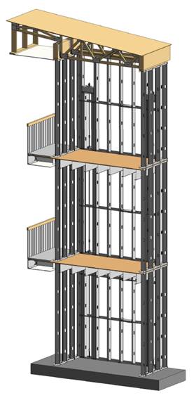
Light-framed CFS over three stories often use continuous rod tie-down systems rather than cold-formed steel hold-downs to resist shear wall overturning forces as they offer increased load capacity. Neglecting the dead load contribution, the amplified seismic load requirement for CFS shear walls using an R greater than 3 results in an 80% increase in the load used to size the continuous rod tie-down system compared to design level loads. For shear walls using an R greater than 3, it is important to note on the design drawings whether the uplift loads shown are ASD, LRFD, amplified ASD or amplified LRFD so the appropriate tie-down system may be designed.
Continuous Rod Tie-Down System Resisting Shear Wall Overturning Forces
Continuous rod tie-down systems are designed not only for strength, but also checked to ensure they do not deflect too much to cause the top of shear wall drift to exceed the code limit or to exceed the 0.20” vertical story deflection limit required by some jurisdictions and ICC-ES AC316. Take-up devices are used in CFS framed structures to take-up construction and settlement gaps that may occur. AISI S200 Section C3.4.4 states that a gap of up to 1/8” might occur between the end of wall framing and the track. The vertical elongation of the continuous rod tie-down system includes rod elongation (PL/AE) and the take-up device deflection due to the seating increment and the deflection under load.
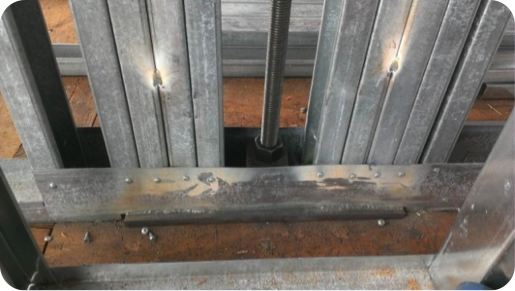
In addition, coordination is important in using continuous rod tie-down systems in CFS structures because the walls are often prefabricated offsite. An example is the consideration of the appropriate detail for the steel bearing plate installed at the floor sheathing in the story above to resist the uplift (tension) force from the story below.
One possible detail is to install the bearing plate in the bottom CFS track under all the CFS chord studs, but it’s important to ensure the bottom track flanges are deep enough to screw them to the stud flanges as the bearing plate can have a thickness of 1 ½” or more and typical tracks use 1 ¼” flanges. It is also important to ensure that the bearing plate width fits in the track. Another possible detail is to install the bearing plate under the CFS track under all the CFS chord studs. However, then it must be cut into the floor sheathing and may cause the bottom track to be raised at the bearing plate. For this detail, the floor shear transfer must be detailed through the ledger into the CFS framing.
Continuous Rod Tie-Down System Steel Bearing Plate Coordination Issues
Concrete Tension Anchorage
The concrete tension anchorage is designed according to ACI 318 Appendix D using the continuous steel rod material and size in accordance with S213 to have the nominal strength to resist the lesser of the amplified seismic force or the maximum load the system can deliver. ACI 318-11 Section D.3.3.4.3 offers four force limits for design of concrete tension anchorage design in Seismic Design Category C through F:
(1) The concrete nominal tension anchorage strength shall be greater than 1.2 times the ductile steel rod nominal tension anchorage strength
(2) The anchorage design strength shall be greater than the maximum tension force that can be delivered by a yielding attachment;
(3) The anchorage design strength shall be greater than the maximum tension force that can be delivered by a non-yielding attachment; and
(4) The anchorage design strength shall be greater than the amplified seismic force.
Typically either option (1) or (4) is used where (1) would lead to less concrete required than (4) if the bolt is efficiently sized while (4) would be required for such conditions as a vertical irregularity. See the concrete anchorage and podium anchorage SE Blog posts for more details.
CFS studs are typically thin and singly symmetric and thus require bracing. AISI S211 (Wall Stud Design Standard) permits two types of bracing design that cannot be combined; sheathing based or steel based. There are limits on the stud axial strength when using sheathing braced design. It’s important to identify on the drawings that the sheathing braces the studs and another load combination must be used for the stud design.
2012 IBC Section 2211.4 requires stud bracing to be designed using either AISI S100 (North American Specification) or S211 (Wall Stud Design Standard). S100-07 Section D3.3 required nominal brace strength is to be 1% of the stud’s nominal compressive axial strength, but S100-12 Section D3.3 changes this to the required brace strength is to be 1% of the stud’s required compressive axial strength (demand load). In addition, D3.3 requires a certain stiffness for each brace. AISI S211 required brace strength is to be 2% of each stud’s required compressive axial strength for axially loaded studs and, for combined bending and axial loads, be designed for the combined brace force per S100 Section D3.2.2 and 2% of the stud’s required compressive axial strength.
There are two primary types of steel stud bracing systems: bridging and strap bracing. U-channel bridging extends through the stud punchouts and is attached to the stud with a clip, of which there are various solutions such as this post on Wall Stud Bridging. Bridging bracing requires coordination with the building elements in the stud bay. It installs on one side of the wall, and does not bump out the wall sheathing. It also requires periodic anchorage to distribute the cumulative bracing loads to the structure for axially loaded studs often using strongback studs and does not require periodic anchorage for laterally loaded studs since the system is in equilibrium as the torsion in the stud is resisted by the U-channel bending.
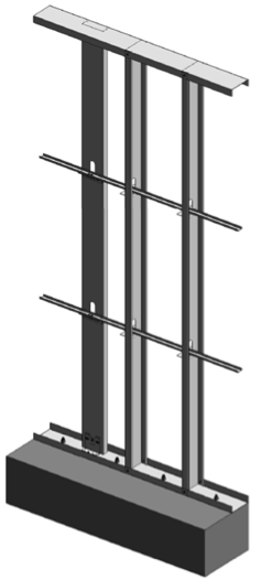
Flat strap bracing is installed on either side of the wall and at locations other than the stud punchout. It bumps out the sheathing and requires periodic anchorage to distribute the cumulative bracing loads to the structure for axially and laterally loaded studs.
Strap and Block Stud Bracing Anchored Periodically to Structure Using Strongbacks
Bridging and Clip Bracing Anchored Periodically to Structure Using StrongbacksBridging and Clip Bracing Anchored Periodically to Structure Using Diagonal Strap Bracing
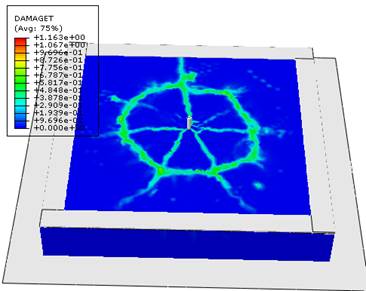
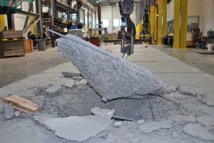
It is hard to believe it has been almost two years since I posted The Anchorage to Concrete Challenge – How Do You Meet It? That post gave a summary of the challenges engineers face when designing anchorage to concrete. Challenges include just doing the calculations (software helps), developing a high enough load, satisfying ductility requirements or designing for overstrength. Over the past several years, Simpson Strong-Tie has worked closely with the Structural Engineers Association of Northern California (SEAONC) to help create more workable concrete anchorage solutions for light-frame construction.
Anchor FEAAnchor BreakoutAnchor Close Up
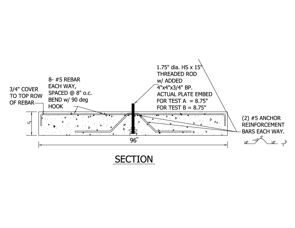
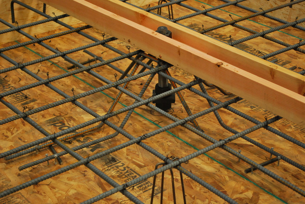
This month’s issue of Structure magazine has an article, Testing Tension-Only Steel Anchor Rods Embedded in Reinforced Concrete Slabs, which provides an update on the ongoing work of SEAONC and Simpson Strong-Tie. The goal of the testing program is to create a useful design methodology that will allow structural engineers to develop the full tensile capacity of high-strength anchor rods in relatively thin (10” to 14”) podium slabs.
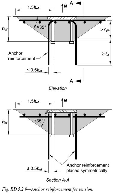
Anchor capacity is limited by steel strength, concrete strength, embedment depth, and edge distances. One way to achieve higher anchor strengths is to design anchor reinforcement per ACI 318-11 Appendix D.
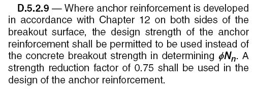
ACI318-11 Figure RD.5.2.9ACI318-11 D.5.2.9
Section D.5.2.9 requires anchor reinforcing to be developed on both sides of the breakout surface. Since this is not practical in thin podium slabs, alternate details using inclined reinforcing perpendicular to the breakout plane were developed and tested.
This month’s Structure magazine article summarizes the test results for anchors located at the interior of the slab, away from edges. Additional testing is needed for anchor solutions at the edge of slab. The anchor reinforcement concepts are similar, yet additional detailing is required to prevent side-face blowout failure modes. This testing is in progress at the Tyrell Gilb Research Laboratory and will be completed later this year.
Did you read the Structure article? What are your thoughts?
We use cookies on this site to enhance your user experience. By clicking "I AGREE" below, you are giving your consent for us to set cookies. Privacy PolicyI AGREE
Privacy & Cookies Policy
Privacy Overview
This website uses cookies to improve your experience while you navigate through the website. Out of these cookies, the cookies that are categorized as necessary are stored on your browser as they are essential for the working of basic functionalities...
Necessary cookies are absolutely essential for the website to function properly. This category only includes cookies that ensures basic functionalities and security features of the website. These cookies do not store any personal information.
Any cookies that may not be particularly necessary for the website to function and is used specifically to collect user personal data via analytics, ads, other embedded contents are termed as non-necessary cookies. It is mandatory to procure user consent prior to running these cookies on your website.