Welding High Strength Anchor Rods

One of the first projects I worked on when I got out of school was the Mexican Heritage Plaza in San Jose, California. It was a 200,000 square-foot facility with a theater, classrooms, art gallery and gardens. It was my first time using ETABs and SAFE for the building frame and mat slab designs, and there was no graphical interface. Text file input – those were the days! I learned how to detail bolted and welded steel connections, and then I got to enjoy every junior engineer’s first right of passage – reviewing shop drawings. It was eye-opening to learn that a detailer needed to translate all the dimensions, size call-outs and typical details into exact measurements down to the sixteenth of an inch for every single member, bolt, and hole.

I am sure I spent too much time reviewing them and checking that all the numbers added up. Photocopying E-size drawings was more expensive than a junior engineer’s time back then, so before I hand copied my mark-ups over to five sets of drawings, I reviewed them with my manager. She circled the high-strength anchor rods for the special moment frames and wrote “Too short – recheck.” I pointed out that I had checked the grout pad, base plate and washer thickness to make sure the anchor rods extensions were long enough to fully thread the nuts on (they just worked). She told me that high-strength anchor lengths were always too short. It didn’t make sense to me at the time, but I marked up the drawings and sent them off. More on this later.

Common specifications for steel anchor rods used for concrete anchorage are ASTM A307, A449 and F1554 Grades 36, 55, 105.  Some of these anchor rods have specifications appropriate for welding.  According to AISC Design Guide 21 on Welded Connections, “unless the supplier of the anchor rod can provide assurance that the compositional limits of ASTM A36 have been achieved, weldability of F1554 Grade 36 should be investigated”.  Both ASTM F1554 Grade 55 and ASTM A307 provide supplementary requirements for welding applications in Section S1.  The S1 requirements limit the percentage of carbon equivalent permitted for the metal alloy.  Where welding is required designers should specify F1554 Grade 36 with the compositional limits of ASTM A36 or F1554 Grade 55 ordered with supplementary requirement S1. ASTM A307 specified with supplementary requirement S1 can be ordered for anchor rods where welding is required.

Threaded Rods
Threaded Rods

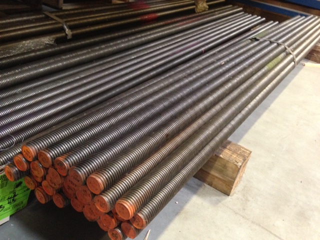
There is a blend of art and science in the manufacturing of high-strength steel anchor rods (ASTM F1554 Grade 105, A325 and A449).  Like a pastry chef, creating a perfectly baked soufflé with the correct ingredients and temperature, modern day blacksmiths achieve a balance of strength and ductility characteristics for anchor rods through controlled quenching and tempering treatments.  The rapid cooling of metal through quenching increases toughness and strength, but it often increases brittleness.  Tempering is a controlled reheating and cooling of the metal which increases ductility after the quenching process.  Precise control of time with the application of temperature during the tempering process is critical to achieve an anchor with well-balanced mechanical properties.

Coupler Nuts
Coupler Nuts

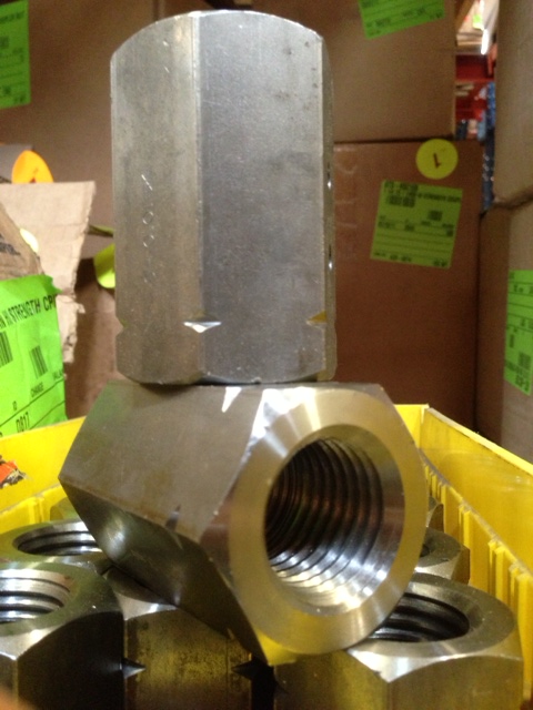
AISC does not recommend welding of high-strength anchor rods including, but not limited to, ASTM F1554 Grade 105, A325, and A449. The heat input from welding can alter the physical properties and other elements from the weld metal are introduced altering the metal alloy for high strength anchors.  Similarly, quenched and tempered steel used to fabricate high strength nuts or couplers is also not suitable for welding.

Now let’s get back to my first steel project. We asked the steel detailer to recheck the anchor rod lengths, and they added 1” of extension above the top of concrete and shipped the assemblies with 16-gage steel templates attached with double nuts. Several templates were damaged in shipping so the contractor fabricated new ones. Somewhere in the process of swapping out templates and reattaching them with double nuts, the anchor rods were set 1” too low. Since the detailer added 1”, everything fit perfectly. And I understood why high-strength anchor rods could never be too long.

3, 2, 1. . .Countdown to Earthquake!

This week, I’d like to introduce Jeff Ellis as a guest blogger for the Structural Engineering Blog. Jeff is the Manager of Codes, Standards and Special Projects for Simpson Strong-Tie. Jeff will be posting occasionally on topics that are relevant to our work, especially related to cold-formed steel (CFS) construction. 

When was the last time you knew an earthquake was coming and witnessed its effects on a building without feeling any shaking yourself? Since the mid- to late ‘90’s, several uni-axial and tri-axial shake tables have been built and used to better understand whole building performance under actual earthquake ground motion in order to improve code requirements and, in some cases, develop performance-based design methods.Continue Reading

Breaking News: Simpson Strong-Tie® Strong Frame® Special Moment Frame Testing Today

Today the NEES-Soft project has begun testing the steel Simpson Strong-Tie® Strong Frame® Special Moment Frame as a retrofit option for soft-story buildings at the NEES outdoor shake table facility at UC San Diego. The testing is focused on validating the FEMA P-807 design procedure, which attempts to create a least-cost retrofit solution by only retrofitting the garage areas of problem buildings.Continue Reading

Steel Moment Frame Beam Bracing

In a previous blog post on soft-story retrofits, I briefly discussed beam bracing requirements for moment frames. This week, I wanted to go into more detail on the subject because it’s important to understand that a typical steel moment frame requires lateral beam bracing to develop its full moment capacity. Figure 1 below shows two common methods of beam bracing. While on the surface determining beam bracing requirements may not appear complicated, there are several items that could prove it to be more challenging than you might think, especially when steel moment frames are used in light frame construction.

Figure 1: Steel Beam Bracing

(A) Braced with kicker and metal deck(1)
(B) Braced with kicker and wood joist/beams(2)

Before going into beam bracing in steel moment frames, it is important to discuss the behavior of a simply supported beam under gravity load. Short beams (Lb < Lp)[3], might not require bracing to achieve the full plastic moment of the beam section. However, when a beam is long (Lb > Lr) and without bracing, the beam can twist or buckle out-of-plane.  Figure 2 illustrates these two behaviors along with the case where the beam length is somewhere in between the two (e.g., Inelastic lateral torsional buckling). In addition, if beam sections are non-compact, flange local buckling (FLB) or web local buckling can occur prior to reaching the beams full plastic moment.

Continue Reading

Congratulations to our Structural Engineering Blog One-Year Anniversary Winners!

To celebrate the first-year anniversary of the launch of our Structural Engineering Blog, in April we hosted a sweepstakes inviting you to comment on the blog or sign up for blog email updates.

Continue Reading

Timber Tower Research Project

In 2009, Simpson Strong-Tie participated in the NEESWood Capstone Test, which was the final experiment in a multi-year study to test and evaluate the seismic performance of various wood-framed buildings. The Capstone Test was a six-story apartment building constructed and tested at the E-Defense test facility, located in Miki, Japan. More information about the Capstone Test is available here.

NEESWood Capstone Test. Photo credit: Simpson Strong-Tie.
NEESWood Capstone Test. Image credit: Simpson Strong-Tie.

I only mention the NEESWood testing because I thought six-stories was pretty tall for wood-framed construction, since U.S. building codes limit us to four or five stories in wood. I recently came across a research project by Skidmore, Owings & Merrill LLP (SOM) for something just a tad taller than that. Looking to minimize the carbon footprint by using timber as the main structural material, SOM published a report for the design a 42-story, 405-ft. tall building. The solution utilizes mass timber for the main structural elements with reinforced concrete at highly stressed areas. The project used the Dewitt-Chestnut Apartments, a 42-story reinforced concrete structure built in 1965, as the benchmark building.

SOM's
SOM Timber Tower. Image credit: Skidmore, Owings, Merrill website.

Abstract for the Timber Tower Research Project along with links to the full report and sketches are on SOM’s website.

So, what do you think of a 42-story wood-framed building? Let us know by posting a Comment.

– Paul

Rebuilding with Simpson Strong-Tie Products After Hurricane Sandy

Our factory in Gallatin, TN held a Fastener Summit Meeting this past June, which brought together people from all areas of our fastener business. Somewhere, sometime we started calling these meetings “Summits” and the name stuck. The purpose of the Summit is to facilitate candid discussions about what we need to do to better support our customers’ needs through new product development, new application testing, literature, training, or sales distribution.

One of our fastener sales specialists shared a great story about a New Jersey town’s decision to build a better boardwalk following Superstorm Sandy. The town of Seaside Heights decided to design and build a boardwalk to better address future storms. Along with being a local icon, the boardwalk is an integral part of the town’s economy.

Seaside Heights boardwalk rebuild.

Working hand in hand with the town’s borough officials, the project’s engineering firm and contractor, our Columbus, OH branch worked to tirelessly to develop construction solutions to save time and money on this critical project. For Simpson Strong-Tie, this involved testing and ramping up production of stainless steel product to ensure no delays for the project.

A little over two months after Seaside Heights Mayor Bill Akers drove the first deck board screw using our Quik Drive auto-feed screw system, the boardwalk was complete. NBC’s Today Show broadcast live from the boardwalk with New Jersey Governor Chris Christie on May 24. There’s also a cool video on the New York Fox News website showing different time lapse views of the build here.

Seaside Heights Mayor Bill Akers drive in the first screw.
Seaside Heights Mayor Bill Akers drives in the first screw.
The Today Show airs live from the reconstructed boardwalk.
NBC’s Today Show airs live from the reconstructed boardwalk.

You can read the full story in the July issue of our Structural Report newsletter.

– Paul

What If You Wrote A Code and Nobody Used It?

Simpson Strong-Tie spends quite a bit of time monitoring the development and adoption of building codes. This effort helps us to have products available to help our customers meet the latest code requirements.

The model codes most commonly used in this country, the International family of codes, are developed by the International Code Council (ICC). ICC lists the following benefits of a uniform, modern set of codes: “Code officials, architects, engineers, designers, and contractors can work with a consistent set of requirements throughout the United States. Manufacturers can put their efforts into research and development rather than designing to different sets of standards and can focus on being more competitive in worldwide markets. Uniform education and certification programs can be used internationally.” ICC offers a statement on why the newest codes should be adopted here.

Nevertheless, for varied reasons, many states do not require adoption of uniform codes statewide. A group composed of national business and consumer organizations, corporations, and emergency management officials is trying to change that. The group is called the BuildStrong Coalition, and they believe that the statewide adoption of building codes will “protect homes and buildings from the devastation of natural disasters.”

The group offers several studies to back this idea. One of the most compelling was a study performed by the Insurance Institute for Business and Home Safety after Hurricane Charley in 2004. The study examined specific houses in the path of the hurricane and compared the damage to the year that the home was built. It showed that in homes built since the adoption of the statewide Florida Building Code, the severity of property losses was reduced by 42 percent, and the frequency of losses was reduced by 60 percent.

The coalition believes that “strong building codes provide our best first line of defense against natural disasters.” It appears that, for whatever reason, the number of disasters has been increasing of late. For example, in the 60’s, there were an average of 19 Major and Emergency Federal Disaster Declarations per year. In the 70’s, the average was 41 per year. In the 80’s, the average was 25 per year. In the 90’s, the average was 52 per year, and since 2000, the average has been 76 Disaster Declarations per year.

The coalition has been working with members of Congress on proposed legislation, the Safe Building Code Incentive Act, which would give states an incentive to adopt and enforce statewide building codes. Rather than mandate state action, the Act would reward states that adopt and enforce nationally recognized model building codes for residential and commercial structures with eligibility for an additional 4% of disaster relief aid after their next disaster strikes.

The Act was recently reintroduced by Senator Menendez and Representative Diaz-Balart. You can read a press release on the reintroduction here.

– Paul

New Simpson Strong-Tie Anchor Designer software

Remember back to the days when you used allowable stress design for designing anchorage to concrete? Once you had your design loads, selecting an anchor was quick and easy. The 1997 UBC covered the anchorage to concrete in less than two pages, so the calculation was painless. Post-installed anchors were even easier, since allowable loads were tabulated and you just needed to apply a couple of edge distance and spacing reductions.

Since the introduction of strength design provisions and the adoption of ACI 318 Appendix D, first in the 2000 IBC, designing code-compliant anchorage to concrete has become much more complex. At least once (and probably not more) armed with a pencil,  calculator, and an eraser, most of us have set out to design a ‘simple’ anchorage to concrete connection using the  Appendix D provisions. Several pages of calculations later (and hopefully with a solution to the problem), most of us, I imagine, came to realize that designing anchorages to concrete by hand required much more time and effort than we anticipated or could allocate time for. As a result, many of us probably created an Excel template to speed up the design process using built-in functions and some Visual Basic programming.

I'm never going for looks on my spreadsheets.
I’m never going for looks on my spreadsheets.

The question is: are you still using the template?

For me, the answer is an emphatic “NO”, mainly because the spreadsheet I created has limited capability given the complexity in adapting the design methodology to complex anchor layouts, changes to the design provisions with each new code edition, and the need to add/modify data each time a new post-installed anchor product is introduced.

Continue Reading

What Did Sandy Teach Us?

In the weeks following Hurricane Sandy, I had an opportunity to visit some of the hardest hit communities in the region. At the time, many of New Jersey’s barrier islands were still completely closed off to civilian traffic and all accessible bridges were blocked by military guards. Our local territory manager has great relationships with building departments, so we were able to walk portions of Long Beach Island, NJ with an inspector. The storm surge washed out several sections of the protective sand dunes on the south end of the island in the neighborhood of Holgate and this is where we spent much of the day.

Holgate, NJ
Holgate, NJ
Scoured foundation temporarily shored. Holgate, NJ.

For a structural engineer, there was a lot to observe and many things I could write about here (maybe a future post), but what strikes me the most when looking back is the long- term impact this event will have on the region. The cost of Sandy goes beyond the loss of life and property (72 lives, $50 billion and growing). It would be difficult to estimate a dollar amount that accounts for the displacement of people and disruption to their lives, the hit to local economies that depend heavily on tourism, and the effect on the national economy and taxpayers; but I imagine it would be a staggering sum. So what, if anything, can structural engineers do about it?Continue Reading