This post is the second of a two-part series on the results of research on anchorage in reinforced brick. The research was done to shed light on what tensile values can be expected for adhesive anchors. In last week’s post, we covered the test set-up. This week, we’re taking a look at our results and findings.Continue Reading
Category: Building Codes
It can be hard to keep up with or understand all of the building codes. That’s where Simpson Strong-Tie’s engineers coming in.
New Treatment of Shear Wall Aspect Ratios in the 2015 SDPWS
This post was co-written by Simpson Engineer Randy Shackelford and AWC Engineer Phil Line.
The 2015 International Building Code references a newly updated 2015 Edition of the American Wood Council Special Design Provisions for Wind and Seismic standard (SDPWS). The updated SDPWS contains new provisions for design of high aspect ratio shear walls. For wood structural panels shear walls, the term high aspect ratio is considered to apply to walls with an aspect ratio greater than 2:1.
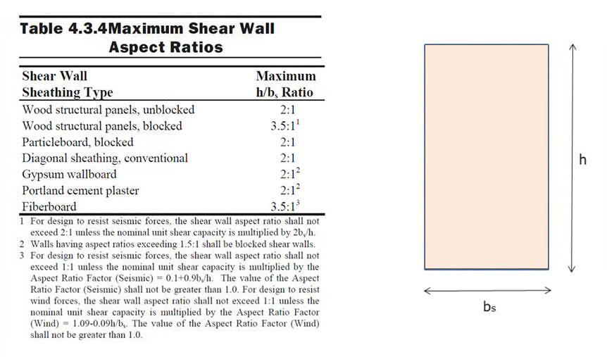
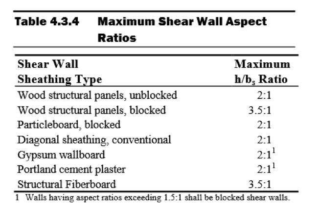
In the 2015 SDPWS, reduction factors for high aspect ratio shear walls are no longer contained in the footnotes to Table 4.3.4 (See Figure 2). Instead, these factors are included in new provisions accounting for the reduced strength and stiffness of high aspect ratio shear walls.
Deflection Compatibility – Calculation Method
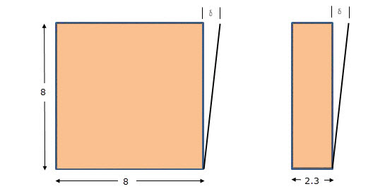
New Section 4.3.3.4.1 states that “Shear distribution to individual shear walls in a shear wall line shall provide the same calculated deflection, δsw, in each shear wall.” Using this equal deflection calculation method for distribution of shear, the unit shear assigned to each shear wall within a shear wall line varies based on its stiffness relative to that of the other shear walls in the shear wall line. Thus, a shear wall having relatively low stiffness, as is the case of a high aspect ratio shear wall within a shear wall line containing a longer shear wall, is assigned a reduced unit shear (see Figure 3).
In addition, Section 4.3.4.2 contains a new aspect ratio factor, 1.25 – 0.125h/bs, that specifically accounts for the reduced unit shear capacity of high aspect ratio shear walls. The strength reduction varies linearly from 1.00 for a 2:1 aspect ratio shear wall to 0.81 for a 3.5:1 aspect ratio shear wall. Notably, this strength reduction applies for shear walls resisting either seismic forces or wind forces. For both wind and seismic, the controlling unit shear capacity is the smaller of the values from strength criteria of 4.3.4.2 or deflection compatibility criteria or 4.3.3.4.1.
Deflection Compatibility – 2bs/h Adjustment Factor Method
The 2bs/h factor, previously addressed by footnote 1 of Table 4.3.4, is now an alternative to the equal deflection calculation method of 4.3.3.4.1 and applies to shear walls resisting either wind or seismic forces. This adjustment factor method allows the designer to distribute shear in proportion to shear wall strength provided that shear walls with high aspect ratio have strength adjusted by the 2bs/h factor. The strength reduction varies linearly from 1.00 for 2:1 aspect ratio shear walls to 0.57 for 3.5:1 aspect ratio shear walls. This adjustment factor method provides roughly similar designs to the equal deflection calculation method for a shear wall line comprised of a 1:1 aspect ratio wall segment in combination with a high aspect ratio shear wall segment.
In prior editions of SDPWS, a common misunderstanding was that the 2bs/h factor represented an actual reduction in unit shear capacity for high aspect ratio shear walls as opposed to a reduction factor to account for stiffness compatibility. The actual reduction in unit shear capacity of high aspect ratio shear walls is represented by the factor, 1.25 – 0.125h/bs, as noted previously. The 2bs/h factor is the more severe of the two factors and is not applied simultaneously with the 1.25-0.125h/bs factor.
What are the major implications for design?
- For seismic design, the 2bs/h factor method continues unchanged, but is presented as an alternative to the equal deflection method in 4.3.3.4.1 for providing deflection compatibility. The equal deflection calculation method can produce both more and less efficient designs that may result from the 2bs/h factor method depending on the relative stiffness of shear walls in the wall line. For example, design unit shear for shear wall lines comprised entirely of 3.5:1 aspect ratio shear walls can be as much as 40% greater (i.e. 0.81/0.57=1.42) than prior editions if not limited by seismic drift criteria.
- For wind design, high aspect ratio shear wall factors apply for the first time. For shear walls with 3.5:1 aspect ratio, unit shear capacity is reduced to not more than 81% of that used in prior editions. The actual reduction will vary by actual method used to account for deflection compatibility.
- The equal deflection calculation method is sensitive to many factors in the shear wall deflection calculation including hold-down slip, sheathing type and nailing, and framing moisture content. The familiar 2bs/h factor method for deflection compatibility is less sensitive to factors that affect shear wall deflection calculations and in many cases will produce more efficient designs.
As the 2015 International Building Code is adopted in various jurisdictions, designers will need to be aware of these new requirements for design of high aspect ratio shear walls. The 2015 SDPWS also contains other important revisions that designers should pay attention to. The American Wood Council provides a read-only version of the standard on their website that is available free of charge.
Please contribute your thoughts to these new requirements in the comments below.
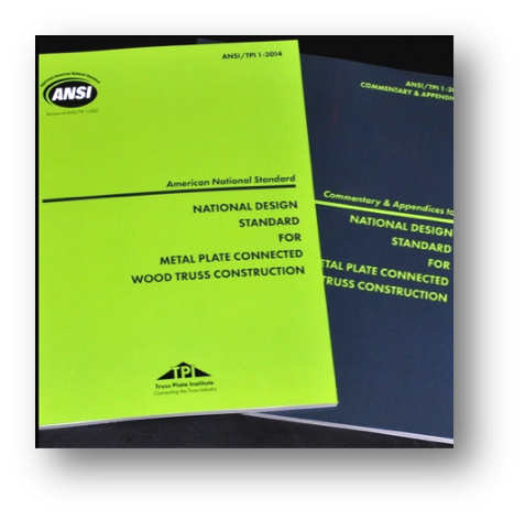
The New Truss Design Standard: Enter to Win A Copy of ANSI/TPI 1-2014 National Design Standard for Metal Plate Connected Wood Truss Construction
If you are like me, then you enjoy this time of the year. Instead of looking back and reviewing the events of the past year, this is the month for looking ahead at the year to come and what’s in store. So what is in store for 2015?
For the truss industry, there is a new truss design standard that was just released the last week of December. Still hot off the press, the ANSI/TPI 1-2014 standard is a revision to the 2007 edition and is referenced in the 2015 International Building Codes.
While the 2015 I-Codes might take some time for some municipalities to adopt, others are gearing up for adoption of the 2015 I-Codes as early as mid-2015. Either way, it is always good to know what is in the latest and greatest code-referenced design standards. So here’s a look at the new ANSI/TPI 1-2014 truss design standard:
First, here is a brief primer on the TPI 1 standard. The Truss Plate Institute (TPI) published the first truss design criteria in 1960. Many updates to these design criteria followed after that, and in 1995, TPI published its first ANSI-accredited truss design standard, ANSI/TPI 1-1995. Subsequent editions of this American National Standard have included ANSI/TPI 1-2002, ANSI/TPI 1-2007, and now ANSI/TPI 1-2014. All of the TPI standards, including archived copies going all the way back to TPI-60, are available from TPI (www.tpinst.org). Here is a link to the overview of non-editorial changes from ANSI/TPI 1-2007 to ANSI-TPI 1-2014.
While the 2007 edition included many significant revisions to the previous edition, the 2014 standard has relatively few substantive changes to the 2007 edition, which is good news for those who are still trying to catch up. Chapter 2 covers the design responsibilities involved in metal plate connected wood truss construction and looks different at first glance because it has been reorganized. However, the actual “Design Responsibilities” as they were defined in TPI 1-2007 have not changed.
In short, two separate sections in TPI 1-2007, which address design responsibilities in projects that require registered design professionals and projects that do not, have now been combined into one section. The “Truss Design Engineer” is simply referred to as the “Truss Designer” and the “Registered Design Professional for the Building” is simply the “Building Designer.” If the project requires registered design professionals, then the Truss Designer and Building Designer will be registered design professionals. Regardless of whether or not those two parties are registered design professionals, their responsibilities relating to the design and application of metal plate connected wood trusses are the same, so defining those responsibilities once within the TPI standard simplifies things and makes more sense.
Not new to the wood industry, but new to TPI 1-2014, are provisions for Load and Resistance Factor Design (LRFD). AF&PA incorporated LRFD provisions into the 2005 National Design Specification (NDS) for Wood Construction, and the TPI standard has followed suit, using the same basic approach as the NDS.
The section in TPI 1-2014 with the most changes is the section on deflection criteria. The deflection criteria have been revised in the last three editions of the TPI standard. Starting in TPI 1-2002, a requirement was added to consider creep in total deflection calculations. However, specific creep factors were not specified in the standard and were only presented in the Commentary. In the 2007 edition, creep factors were moved into the standard, and the total deflection calculation explicitly specified a component due to creep of no less than 50 or 100 percent of the initial deflection for long-term loads for dry and green (wet service) use, respectively. This was consistent with the 1.5 and 2.0 creep factors specified in the NDS for total deflection calculations for seasoned and unseasoned conditions.
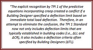
Between the 2007 and 2014 editions, an inconsistency was discovered between the TPI 1 deflection criteria and the deflection limits in the U.S. model building codes. While the intent of the TPI standard was to present the same basic L/xxx deflection limits for Live Load and Total Load as the model building codes, it was discovered that the IBC deflection limits for “DL + LL” were actually intended to address only the creep portion of the dead load deflection plus the immediate live load deflection. So although long-term deflection including proper creep considerations can be an important consideration in the overall design of the building, it is not intended to be used to limit the design of a truss with respect to building-code established limits on vertical deflection.
To resolve the issue of inconsistent methods used in the building industry to specify deflection limits, the 2014 edition now distinguishes between the following:
• “Deflection due to Live Load Plus Creep Component of Deflection due to Dead Load” for purposes of meeting the IBC deflection limits for DD + LL, which is defined as
ΔCR = Δ LL + (Kcr ‐1) x Δ DL
• “Long-Term Deflection”, which includes the full effect of creep but for which there are no explicit deflection limits specified in TPI
• “Deflection due to Total Load”, which is based on the full load (including both dead load and live load), but includes no explicit creep factors. The deflection due to total load has the same deflection limits as the IBC deflection limits for DD + LL, but this is not a mandatory check in TPI; it only applies to trusses if the Building Designer specifies that such a check due to total load be performed. Further, any consideration for creep in that calculation would also have to be specified by the Building Designer.
In recognition of the increased creep in trusses compared to solid sawn beams, the creep factors have been increased to 2.0 and 3.0 for dry and green (wet service) use, respectively. For purposes of deflection checks in accordance with the IBC, these factors reduce to 1.0 and 2.0, respectively, since the equation for “Deflection due to Live Load Plus Creep Component of Deflection due to Dead Load” uses KCR-1 rather than KCR as the factor on the immediate deflection due to dead load.
What does this all mean? For the majority of truss applications (e.g., dry-service), the effect of switching from TPI 1-2007 to TPI 1-2014 will be a change in creep factor from 1.5 to 1.0, unless additional requirements are specified by the Building Designer. Those additional requirements may include a limit on long-term deflection or a check for total load deflection (subject to the TPI deflection limits), including any considerations for creep.
A complete listing of the changes in TPI 1-2014 and more discussion about these changes are available in the TPI 1-2014 Commentary.
Now is your chance to win a copy of the ANSI/TPI 1-2014 standard for your own design library! Simply post a truss-related question, comment or idea for a future truss-related blog topic, and we will enter you into a drawing during the week of Jan 15-22. One winner will be picked at random. We look forward to hearing from you!
Here Come 2015 IBC Changes!
All of us here at Simpson Strong-Tie hope you had a happy and successful 2014. It seems that the folks at the International Code Council had a good year. True to their plan, the 2015 editions of the International Codes were published during the summer so that they are ready for adoption in 2015.
Simpson Strong-Tie was tracking a number of issues during the development of the 2015 International Building Code and International Residential Code. Here is a summary of some of the significant changes that users will see in the 2015 International Building Code (IBC).
One significant change affecting Simpson Strong-Tie was the removal of the requirements for evaluation of joist hangers and similar devices from Chapter 17, and the revision of Sections 2303.5 and 2304.10.3 to reference ASTM D 7147 as the test standard for joist hangers.
Since the primary reference standard for design in Chapter 16, ASCE 7-10 has not changed; there were not a lot of significant changes in that chapter. The definitions of “Diaphragm, rigid” and “Diaphragm, flexible” were deleted from Chapter 2, and a sentence was added to 1604.4 stating when a diaphragm can be considered rigid, along with a reference to ASCE 7 for determining when designs must account for increased forces from torsion due to eccentricity in the lateral force resisting system.
In Chapter 19, significant improvements were made to the sections that modify ACI 318 so that the IBC and the standard are coordinated, correcting the problems in the 2012 IBC. In addition, Sections 1908 (ASD design of anchorage to concrete) and 1909 (strength design of anchorage to concrete) were deleted to remove any conflict with ACI 318 anchor design methods.
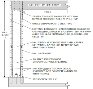
In Chapter 23, a new section was added to address cross-laminated timber, requiring that they be manufactured and identified as required in APA PRG 320. The wood framing fastening schedule was completely reorganized to make it easier to use and the requirements for protection of wood from decay and termites were rewritten. Section 2308 on Conventional Light-Frame Construction was completely reorganized with significant revisions to the wall bracing section. As discussed in an earlier blog post, the holdown requirement for the portal frame with holdowns (now called PFH bracing method in the 2015 IBC) has been reduced from a required capacity of 4,200 pounds to 3,500 pounds.
For designers, some of the most significant changes are in Chapter 35, which lists referenced standards. Some major standards that were updated for this edition of the IBC include ACI318-14, ACI530/530.1-13, several AISI standards (S100-12, S200-12, S214-12, and S220-11), several new and revised ASCE standards (8-14, 24-13, 29-14, 49-07, and 55-10), almost all the AWC standards (WFCM-2015, NDS-2015, STJR-2015, PWF-2015 and SDPWS-2015), AWS D1.4/D1.4M-2011, most NFPA standards (too many to list), PTI DC-10.5-12, SBCA FS 100-12 and TPI 1-14.
Kudos to the American Wood Council. They have posted view-only versions of all their referenced standards online, so designers do not have to buy new editions every time the code changes. AISI also enables one to download PDFs of the framing standards at www.aisistandards.org.
Finally, a couple of ICC Standards were updated to new versions that are referenced in the IBC: ICC-500-14, ICC/NSSA Standard on the Design and Construction of Storm Shelters; and ICC 600-14, Standard for Residential Construction in High-Wind Regions.
A future blog post will cover significant changes in the 2015 IRC. Please share your comments below.
Changes to 2012 IBC for Wind Design
The Greek philosopher Heraclitusis credited with saying “The only thing that is constant is change.”
If that applies to building codes, then it applies doubly to wind design using the 2012 International Building Code® (IBC).
The wind load requirements in Section 1609 of the IBC are based on ASCE 7 and refer to this document for most design information. In the 2012 IBC, the referenced version of ASCE 7 changed from the 2005 edition to the 2010 edition. In ASCE 7-10, the wind design requirements have been completely revised, including a complete design philosophy change.
Wind design has changed from an allowable strength-based philosophy with a load factor of 1 in the ASD load combination to an ultimate strength design philosophy with a load factor of 1 in the strength design load combination. This means wind design has a similar basis as seismic design. So the new load combinations for wind look like this:
Strength Design: 0.9D + 1.0W
Allowable Stress Design: 0.6D + 0.6W
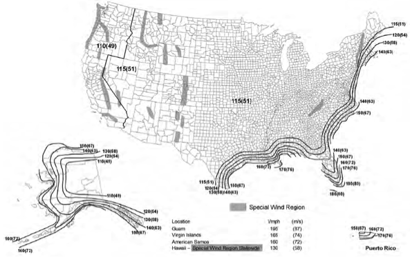
Because of the change in load factor and philosophy, the basic wind speed map had to be altered. In the past, one map was provided and the design return period was increased for certain occupancies by multiplying the load by an importance factor. In ASCE 7-10 there are three maps provided so now an importance factor is no longer needed. The return period of the map depends on the risk to human life, health and welfare that would result from the failure of that type of building. This was previously called the Occupancy Category, but it is now called the Risk Category.
Risk Category III and IV buildings use a basic wind speed map based on a 1,700-year return period. Risk Category II buildings use a basic wind speed map based on a 700-year return period. And Risk Category I buildings use a basic wind speed map based on a 300-year return period. Because of the higher return period, the mapped design wind speed will be much higher than when using previous maps. However, with the lower load factors, actual design loads will be the same or in many areas lower due to other changes in the way the map was developed.
Another change to ASCE 7-10 for wind design is that Exposure D is no longer excluded from hurricane prone regions; so buildings exposed to large bodies of water in hurricane prone regions will have to be designed for Exposure D.
Because of the change in wind speeds, there is a change in the definitions of windborne debris regions. Due to the different wind speed design maps, the windborne debris region will be different depending on the Risk Category of the building being built. The windborne debris region is now defined as areas within hurricane-prone regions that are either within 1 mile of the coastal mean high water line where the ultimate design wind speed is 130 mph or greater; or any areas where the ultimate design wind speed is 140 mph or greater; or Hawaii. Risk Category II buildings and structures and Risk Category III buildings and structures (except health care facilities), use the 700-year Risk Category II map to define wind speeds for the purpose of determining windborne debris regions. Risk Category IV buildings and structures and Risk Category III health care facilities use the 1700-year return Category III/IV wind speed map to define wind speeds for the purpose of determining windborne debris regions.
Finally, a new simplified method for determining wind loading on ENCLOSED SIMPLE DIAPHRAGM BUILDINGS WITH h ≤ 160 ft has been added to ASCE 7-10. This is different from the simplified all heights method in the IBC, so it will be interesting to see which method becomes more widely used. Which method do you prefer? Let us know in the comments below.
Truss-to-Truss and Truss-to-Everything Else Connections
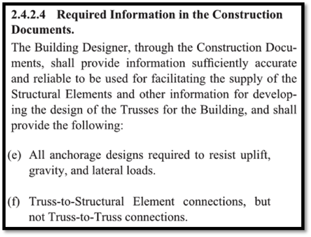
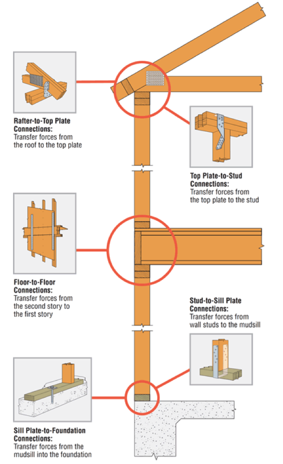
One of the questions I am asked most frequently is “Who is responsible for the truss-to-(fill in the blank) connection? One such example is the truss-to-wall connection. To answer this question, it helps to recognize there are two types of connections: a truss-to-truss connection and a “truss-to-everything-else-except-a-truss” connection. The Truss Designer is responsible for the former, and the Building Designer is responsible for the latter. Pretty simple, right? So why all the questions?
Some people incorrectly assume the Truss Designer is responsible for connecting the truss to everything the truss touches. Then, when the Truss Designer doesn’t specify a connection to something the truss touches (such as a wall), it prompts the question, “Hey, who is responsible for that connection? I thought the Truss Designer was!” In other cases, the person asking the question is actually challenging the answer, such as “Shouldn’t the Truss Designer be specifying the truss-to-wall connection? Why don’t they?” And finally, the question may be prompted at times when the project doesn’t have a Project Engineer (aka the Building Designer), so the question becomes, “Now who is going to specify that connection? It must be the Truss Designer, right?”
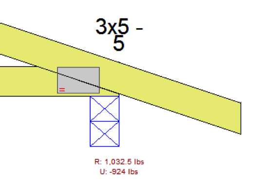
But the Truss Designer isn’t responsible for the truss-to-wall connection – and here’s why. Unless the scope of work has been expanded by contract, the Truss Designer is responsible for designing an individual component. The truss gets designed for a given set of specified loads, environmental conditions, serviceability criteria and support locations, all which are specified by the person responsible for the overall building: the Building Designer. Once designed, the truss will have a maximum download reaction and uplift reaction (if applicable) at each support location. Is that enough information to specify a truss-to-wall connection? No, it is not. First, the Truss Designer may not know what the truss is even sitting on; he or she may only know that the bearing is SPF material and 3 ½” wide. Is it a single top plate or double top plate? Is there a stud below the truss that can be connected to, or is the stud offset? Or, is the truss sitting on a header spanning across a wide window?
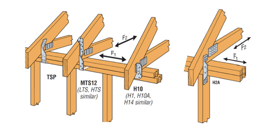
Second, even if the Truss Designer had all of the information regarding the bearing conditions, there is another problem. The Truss Designer has the reactions resulting from the loads applied to the truss. What about the reaction at the top of the wall (perpendicular to the wall) resulting from the lateral loads applied to that wall? And the shear loads acting parallel to the wall as a result of lateral loads applied to the end wall? These loads also need to be resisted by the truss-to-wall connection (hence, the F1 and F2 allowable loads that are published for hurricane ties), so the Truss Designer cannot select an adequate truss-to-wall connection based on the truss reactions alone.
Finally, there’s one more scenario to consider. Say a Building Department requires that truss-to-wall connections must be specified by the Truss Designer on projects that have no Engineer of Record. It wants to ensure trusses are adequately secured to the walls, and the Truss Designer may seem best equipped to determine those connections (this has actually happened in some places). The Truss Designer can find out what exactly the truss is sitting on, and can even calculate some approximate reactions for the top of the wall to conservatively take into account during the selection of the connection. Problem solved? Not entirely. That takes care of the top of the wall, but the load doesn’t stop there. So requiring the Truss Designer to specify the truss-to-wall connection only transfers the problem to the bottom of the wall. Who is going to address those connections?
While most people don’t think of the Truss Designer as being the person responsible for the connections at the bottom of the wall, many do think the Truss Designer should be responsible for the connections at the top of the wall. But because someone – namely, the Building Designer – still needs to ensure that a continuous load path has been satisfied by the connections in the building, does it really help to increase the scope of work of the Truss Designer to specify the truss-to-wall connection?
Let us know your thoughts in the comments below.
Remembering Loma Prieta
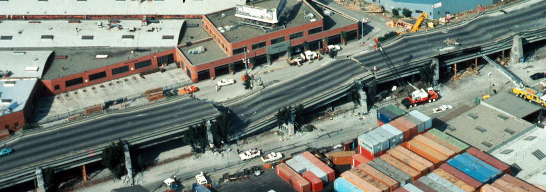
We all know that earthquakes physically shape the landscape here in California, but they shape careers as well. Earthquakes I felt while growing up in California’s southern San Joaquin Valley got me thinking about engineering as a career while in high school. When the Loma Prieta earthquake struck on October 17, 1989, like many of you I was watching the World Series live on television and thus got to see the earthquake live as well. I was in my senior year of college at the time, studying Civil Engineering with a structural emphasis. This earthquake cemented the direction I would take in my career. I wanted to be a structural engineer, and I wanted to design buildings that would not fall down in earthquakes.
Applying new FEMA P-807 Weak Story Tool to Soft-Story Retrofit
We have written about San Francisco’s Soft-Story Retrofit Ordinance and Soft-Story Retrofits before on the blog. I wanted to discuss in more detail the issues with soft story buildings and FEMA’s new tool for addressing them. Under the San Francisco Ordinance, wood-framed residential structures that have two or more stories over a “soft” or “weak” story require seismic retrofit. So far, more than 6,000 property owners have been notified about complying with the mandate.Continue Reading
Changes in IBC from 2009 to 2012: Seismic Design
The transition from one building code to the next always begs the question, “how is the newer code different?” There are several changes between the 2009 IBC and 2012 IBC that will change the way designers approach seismic design. This blog post is a broad overview of some of the changes. Since it’s not practical to cover all the changes between the previous and new codes in detail in one post, the discussion will be mainly on 2012 IBC and the corresponding ASCE7-10 reference standard.
The seismic ground motion maps have been updated to match ASCE7-10. The titles of the maps in IBC were revised from “Maximum Considered Earthquake Ground Motion” to “Risk-Targeted Maximum Considered Earthquake (MCER) Ground Motion Response Accelerations” in order to reflect the titles in 2009 NEHRP and ASCE 7-10. As in previous editions, some areas will prove difficult to read due to the contour lines, so the USGS site and GPS coordinates are recommended (http://earthquake.usgs.gov). Additional information about changes made for 2009 NEHRP is available at www.nibs.org or www.bssconline.org.
The term “occupancy category” was replaced with “risk category” in the 2012 IBC for consistency with the term used in ASCE 7-10. This change was made because it was decided that the use of the word “occupancy” implied the category was directly tied to occupancy classifications in the code, while the word “risk” more accurately communicates that the category is based on acceptable risk of failure.
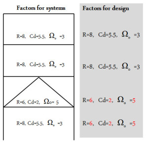
ASCE7-10 revised the way designers use the corresponding Drift amplification, Cd, and Overstrength factor, Ωo, of the Response modification factor, R. In ASCE7-05, when there is a vertical combination of different R-values, the Cd, and Ωo cannot decrease as you go down each level of a building. In ASCE7-10 (12.2.3.1), the Cd and Ωo always correspond to the R-Value as you go down. The adjacent figure illustrates the new provision to use the corresponding Cd, and Ωo with the R-value at each level.
ASCE7-10 (12.3.4.1) added a clarification for out-of-plane anchorage forces where the redundancy factor, p = 1.0. The intent of the redundancy factor was to ensure the vertical seismic-resisting system with insufficient redundancy had adequate strength. The design forces for out-of-plane wall loading are not redundancy requirements. ASCE7-10 (12.11.12) revised the out-of-plane wall anchorage force equation where the anchorage forces are reduced for shorter diaphragm spans.
Light-frame construction structures are no longer exempt from amplification of accidental torsion in ASCE7-10 (12.8.4.3). There are many structures vulnerable to torsional effects including some “tuck under” parking buildings that are often light-frame structures. See posts titled Soft-Story Retrofits and City of San Francisco Implements Soft-Story Retrofit Ordinance for more discussion of soft-story, light-frame buildings.
This is just a brief summary of changes related to seismic design found in the 2012 IBC. What are other changes that will modify your approach to seismic design?
Changes Made to ACI 318 With Respect to Adhesives Anchors in Concrete: What Engineers Need to Know
For the first time, ACI 318 – 11 includes a design provision for adhesive anchors in concrete. Previously, adhesive anchors were designed according to provisions found in both ICC Evaluation Service (ICC-ES) AC308 and ACI 318 – 08. A relatively new standard, ACI 355.4, must be used to qualify adhesive anchors in concrete. This new standard, along with ACI 318 – 11, contains important changes that will affect anchor systems designed to the 2012 IBC. Not all changes are discussed here. I will only focus on what you – the engineer – should be aware of.
ACI 355.4 requires that adhesive anchors in concrete be evaluated using a bond strength (measured in terms of psi and used with the surface area of the embedded portion of the anchor) that corresponds to a long-term temperature (LTT) of 110 degrees F to account for potential elevated temperature exposure conditions. This wasn’t necessarily the case previously where, for example, the engineer could elect to use a temperature category that listed bond strength values based on a LTT of 75 degrees F. The issue here is creep.
Creep, in the world of adhesive anchors, looks at how well the anchor can resist load without too much axial displacement over a period of not minutes, not hours, not even years but decades. As a general rule, it’s no surprise that creep worsens as the temperature rises for almost any material. In our case, the bond strength is effectively reduced. Most adhesives, if not all, currently list bond strength values that correspond to a LTT of 110 degrees F. Make sure to select the temperature category that meets this minimum requirement. Some adhesives will experience a reduction in bond strength at an LTT of 110 degrees F, some won’t.
What about applications involving short-term-only loading? Is creep still relevant? Generally, you’ll find that adhesive anchors negatively impacted by the higher LTT requirement will gain back much of their load for seismic/wind-only load applications. So creep becomes irrelevant.
While adhesive anchors used solely for the purpose of resisting short-term loads will remain largely unaffected by this code change, significant changes have been made to the design and installation of adhesive anchors when used for sustained loading applications (e.g. dead load, live load, etc.).
First, the bond strength must be reduced by a factor of 0.55 as compared to 0.75 under the previous code (following ICC-ES AC308). New to the code, section D.9.2.2 of ACI 318 App. D requires that adhesive anchors used for resisting sustained loads be installed by someone who has taken the Adhesive Anchor Installation Certification (AAIC) program. The installer must show proof that he/she is certified by passing both a written and performance examination. Installing adhesive overhead requires some skill. So it’s no surprise that the installer must satisfactorily demonstrate proficiency by blindly installing adhesive overhead into an inverted test tube that will later be cut in half and graded for the presence of voids. Figure 1 shows no voids, so the installer passed.
However, exceptions do exist. If you’re working on a hospital or school in California, the 2013 CBC (Table 1705A.3 footnote c) requires that all horizontal and overhead adhesives anchors – irrespective of load condition – be installed by a Certified Adhesive Anchor Installer (CAAI). This deviates from ACI 318 D.9.2.2.
Arguably, with AAIC, there’s an added cost to using adhesives for anchorage designed for sustained loading. However, for sustained loading applications best suited for adhesive anchors it should come as peace of mind to the engineer, owner, contractor and other parties involved with the construction project that a certified installer has been employed to ensure that the adhesive anchor has been installed in accordance with the manufacturer’s printed installation instructions.
While the engineer should be aware of the above limitations placed on adhesive anchors, by no means should it hamper their design. There are several options available to the engineer. Table 1 compares the tensile design strength of three common types of anchors – two adhesives, two mechanical anchors (one screw and one expansion type) – determined using the new design provision ACI 318 -11. While the creep test results show a reduced capacity for adhesive A, it does show a significant increase in load for seismic-only applications because , as we discussed earlier, creep is no longer an issue. Some adhesives, like adhesive B, will do well under the creep test (at an elevated LTT of 110 degrees F), so any capacity increase for seismic-only applications will be small.
What three important points can we glean from Table 1? First, all things being equal, mechanical anchors will typically achieve higher “code values” for sustained loading applications relative to adhesives. Second, mechanical anchors are easier to install overhead. Third, AAIC is not required for mechanical anchors. While these reasons support using mechanical anchors for overhead anchorage, doing so is nothing new. The bulk of overhead attachments have almost always been made with mechanical anchors mainly because it’s just easier to do it that way.
Perhaps up to 95% of adhesives are used to secure rebar to concrete – we’ll call them rebar dowels. Like any anchor, rebar dowels can be used to resist seismic and/or sustained loads. While the exact breakdown is hard to determine, arguably, the bulk of rebar dowels in the west coast are found in seismic retrofits and renovations used to thicken walls, tie-in new concrete shear walls, connect new drag struts, strengthen existing concrete elements, etc., all for the purpose of strengthening the lateral capacity of the existing structure to withstand greater earthquake and/or wind loads. These typically won’t require a CAAI, but it might if it’s a school or hospital project that requires overhead or horizontal anchors. Some rebar dowels are used for enlarging footings to withstand greater dead and live loads, so these would require a CAAI. Remember: the bond strength can be lower than expected for sustained loading applications, so you may want to use an adhesive that does well at a LTT of 110 degrees F if that’s what your design requires.
One new benefit of ACI 318 is that the engineer can now design adhesive anchors to go into lightweight concrete using the factors found in section D.3.6.
One significant change engineers should include in their specification is that the concrete must be aged at least 21 days before installing an adhesive. Previously, the industry standard was to wait seven days. For additional information regarding adhesives installed into younger normal-weight concrete, read the following Simpson Strong-Tie engineering letter: http://www.strongtie.com/ftp/letters/generic/L-A-ADHGRNCON14.pdf
What are you experiencing in the design of your anchors in your jurisdictions? Leave a comment down below because we would like to know.