There certainly seems to be increased awareness of the potential for damage and injury from tornadoes these days. Recent information published by the Federal Emergency Management Agency (FEMA) and the Federal Alliance for Safe Homes (FLASH) help explain that. This increased awareness has led to a growing interest in tornado shelters for protection of life and property.
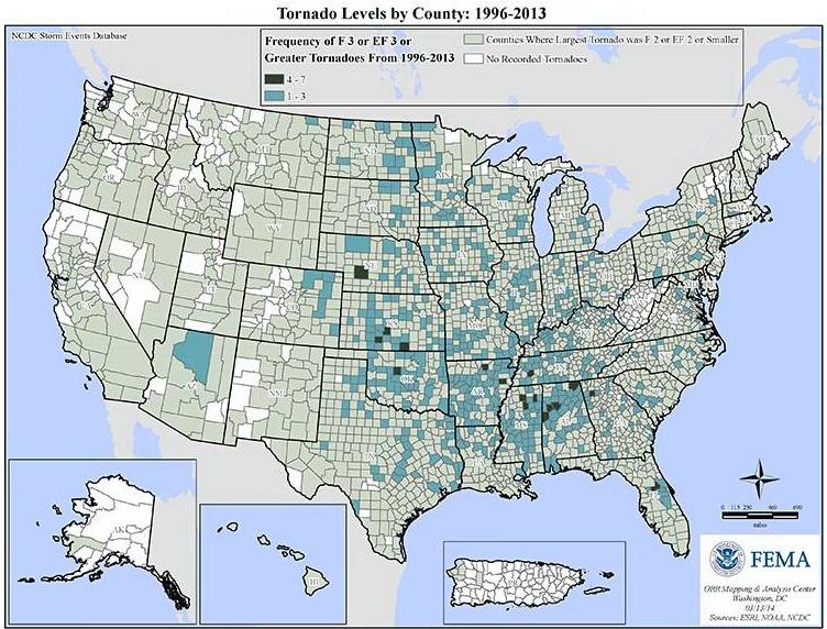
This FEMA graphic shows that most areas of the United States have been affected by a tornado at some point since 1996, and many have been affected by one or more strong tornadoes (EF3 or greater).
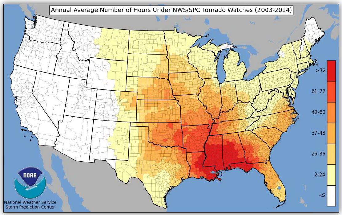
Living in North Texas near the Simpson Strong-Tie manufacturing plant in McKinney, Texas, I know all too well the sinking feeling of hearing the tornado sirens and turning on the TV to find you are under a tornado watch. FLASH recently published a graphic developed by the National Weather Service that shows the large number of U.S. counties that have been under a tornado watch between 2003-2014, and the high number of warnings that some counties experienced.
Other than moving to an area that has fewer tornadoes, one of the best ways to protect your family and at least have more peace of mind during tornado season is to have a tornado shelter or safe room. These structures are designed and tested to resist the highest winds that meteorologists and engineers believe occur at ground level during a tornado and the debris that is contained in tornado winds.
Tornado shelters can be either pre-fabricated and installed by a specialty shelter manufacturer, or can be site-built from a designed plan or pre-engineered plan. A good source for information on pre-fabricated shelters is the National Storm Shelter Association, a self-policing organization that has strict requirements for the design, testing and installation of its members’ shelters.
FEMA publishes a document, P-320, Taking Shelter from the Storm, that provides good information on safe rooms in general, as well as several pre-engineered plans for tornado safe rooms.
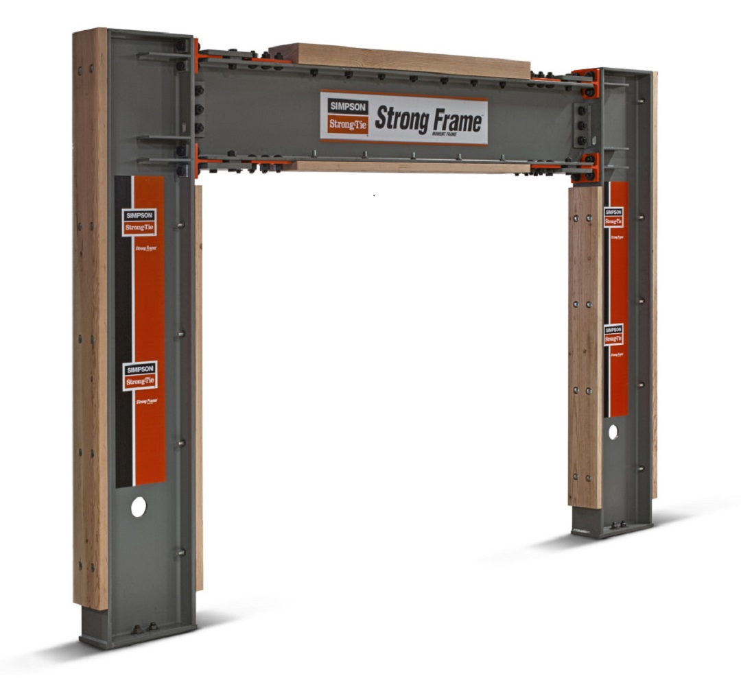
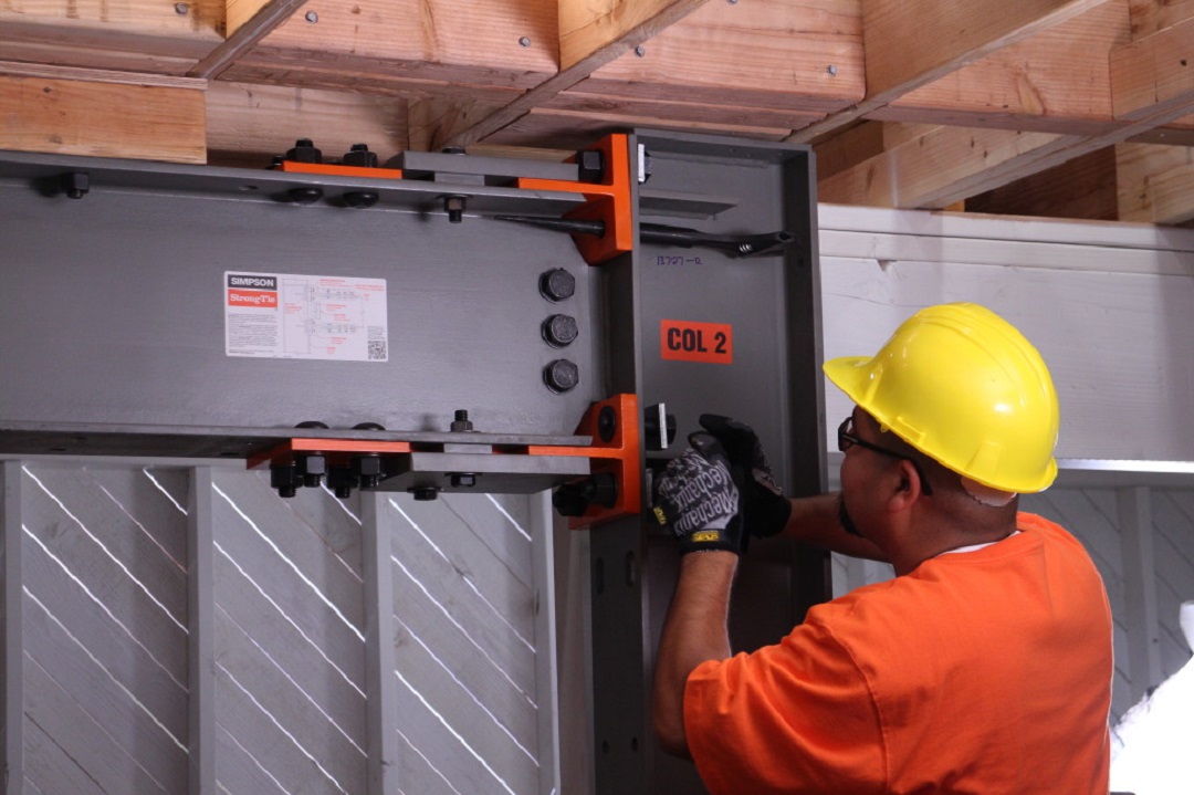
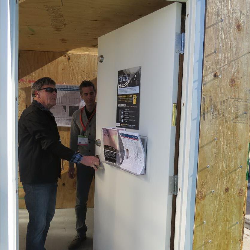
To highlight the different types of safe rooms covered by FEMA P-320, FEMA, FLASH and the Portland Cement Association (PCA) sponsored an exhibit at January’s International Builder’s Show. The exhibit was called the “Home Safe Home Tornado Saferoom Showcase.” It featured six different types of saferooms that builders could incorporate into the homes they build. Simpson Strong-Tie and the American Wood Council collaborated to build a wood frame with steel sheathing safe room meeting the FEMA P-320 plans. Other safe rooms shown at the exhibit included pre-cast concrete and pre-manufactured steel shelters manufactured by NSSA members, and reinforced CMU, ICF cast-in-place concrete and aluminum formed cast-in-place concrete built to FEMA P-320 plans.
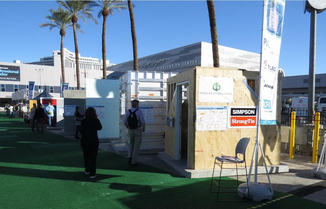
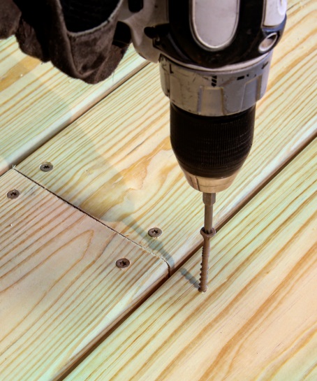
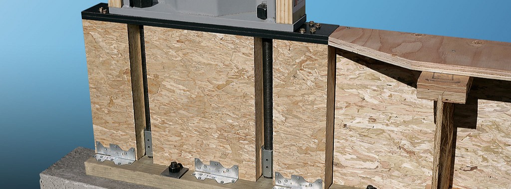
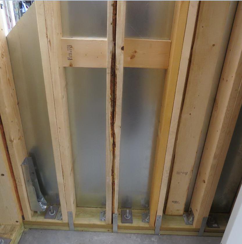
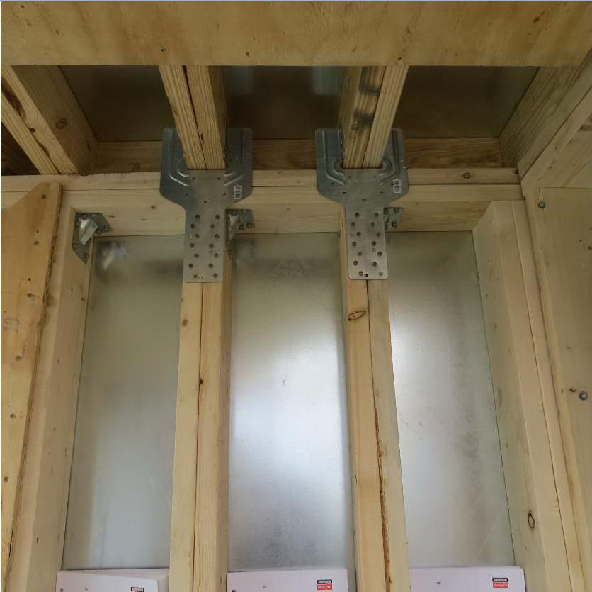
Simpson Strong-Tie staff in McKinney, Texas, constructed the wood frame/steel sheathing safe room in panels and shipped it to the show. It was built from locally sourced lumber, readily available fasteners and connectors and sheets of 16 ga. steel (which we happen to keep here at the factory). It had cut-away sheathing at the corners to show the three layers of sheathing needed. Our message to builders was that this type of shelter would be the easiest for their framers to build on their sites.
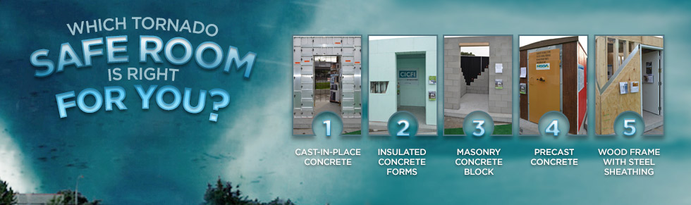
The sponsors of the exhibit took advantage of the variety of safe rooms in one place to film a video series, “Which Tornado Safe Room is Right for You?” The videos are posted at the FLASH StrongHomes channel on YouTube. The series provides comparative information on cast-in-place, concrete block masonry, insulated concrete forms, precast concrete and wood-frame safe rooms, with the goal of helping consumers to better understand their tornado safe room options.
“Today’s marketplace offers an unprecedented range of high-performing, affordable options to save lives and preserve peace of mind for the millions of families in the path of severe weather,” said FLASH President and CEO Leslie Chapman-Henderson. “These videos will help families understand their options for a properly built safe room that will deliver life safety when it counts.”
FLASH released the videos earlier this month as part America’s PrepareAthon!, a grassroots campaign to increase community emergency preparedness and resilience through hazard-specific drills, group discussions and exercises. The overall goal of the program is to get individuals to understand which disasters could happen in their community, know what to do to be safe and mitigate damage from those disasters, take action to increase their preparedness, and go one step farther by participating in resilience planning for their community. Currently, the program focuses on preparing for the disasters of tornadoes, hurricanes, floods, wildfires, earthquakes and winter storms.
Do you know what the risk of disasters is in your community? If you are subject to tornado risk, would you like to build your own safe room, have one built to pre-engineered plans or buy one from a reputable manufacturer? Let us know in the comments below.