Galvanic Corrosion

This week we are blogging about being “galvanic,” and we don’t mean with respect to people, but with respect to the corrosion that occurs between dissimilar metals.

Here is a question, and it is not a joke: What is one significant result that can occur when you have both electrochemical activity and intimate contact?  The answer is galvanic corrosion.

Galvanic corrosion can take place when two or more metals of different electrochemical activity are in intimate contact in the presence of an electrolyte. The dissimilar metals form a galvanic couple, and with the aid of the electrolyte, a galvanic current flows between the metals of the galvanic couple. The more anodic metal corrodes in the presence of the more cathodic metal. In fastening systems, this can be a significant issue because the metal of the fastener often does not match that of the connection materials, making their electrochemical activity dissimilar.

Let’s examine the requirements for galvanic corrosion to occur.

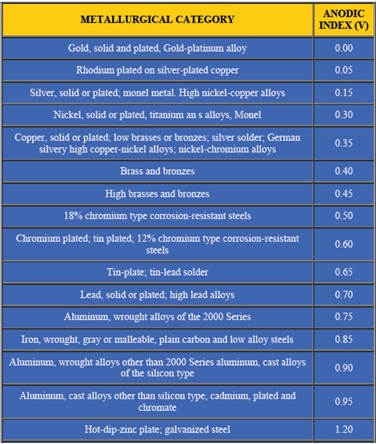
First – In the most common instance, the metals are dissimilar, which means that the metals have different chemical potentials. You may be familiar with the galvanic series where metals are rated by their tendency to give up electrons in a salt-water solution. See Figure 1 for a chart of the galvanic series. The chart is structured with the most cathodic metals at the top and progresses to the most anodic at the bottom. The anodic index shown in the chart is normalized so that gold is the minimum numerical value, while zinc has the greatest numerical value. Stainless steel (300 series) is hidden in the terminology of “18% Chromium type corrosion-resistant steels.”  In this chart, the stainless steel is assumed to be passivated.

Second – The metals must be in direct contact.

Third – An electrolyte must be present to facilitate the movement of electrons. The electrolyte in construction environments is usually plain water that occurs in the form of precipitation, condensation or water splash. Electrolytes that are solutions of chlorides (for example, salt water) are particularly effective electrolytes because they are more conductive.

The size of the anodic and cathodic parts can also be important in galvanic corrosion. If the anodic area is small relative to the cathodic exposed area, then the severity of the anodic corrosion is amplified. We can write an equation to explain the role of area in the galvanic process. We know that no corrosion will occur if the corrosion current density (icor) in μA/cm2 is the same for the anode (icor-a) and the cathode (icor-c). Here we are using a and c as subscripts to identify the anode and the cathode in the galvanic system. We know that current density is a function of total anodic current (I) in μA (where italicized A is amps), and the exposed area (A) is in cm2, which (according to ASTM G102-89) can be written as

icor =   Icor/A

No galvanic corrosion transpires if icor-a for the anodic material is equivalent to icor-c of the cathodic material, which is to say Icor/Aa = Icor/Ac. However, when Ac ≠ Aa, then the corrosion function is not balanced, and relative areas can drive the severity of the galvanic reaction. Inasmuch as area can affect the galvanic process, it will help connection performance if the more anodic material is larger than the more cathodic material. And, by making the Aa>>Ac, we can arrest or minimize the galvanic process. Generally, this means it is best to have a fastener that is more cathodic than the materials being fastened.

We also know that the environment can affect galvanic activity. The differential in the anodic index of dissimilar metals is amplified in harsh environments, but in controlled environments, a greater differential in anodic index can be tolerated.

Let’s summarize some best fastening practices for preventing galvanic conditions that could undermine an otherwise good connection design (Claus, L. 2014. “Galvanic Corrosion.” Fastener Technology, April, pp. 64–66.):

  • Use fasteners that are galvanically similar to the connection materials.
  • Isolate the dissimilar materials by using a plastic washer or durable coating.
  • Prevent entrapment of water or shield the connection from direct weather exposure.
  • If the fasteners are dissimilar from the connection materials, choose a fastener that is cathodic relative to the connection materials.
Figure 1. Galvanic series with anodic index voltages (http://engineersedge.com/galvanic_compatibility )
Figure 1. Galvanic series with anodic index voltages (http://engineersedge.com/galvanic_compatibility
)

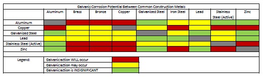
Some good information is available that can help to avoid a galvanic design challenge. First, see Figure 2. This chart provides color-coded galvanic compatibility that is fast and easy to use. The chart suggests material combinations where there will be galvanic action (red), material combination that might demonstrate galvanic activity (yellow), and material combinations that will have insignificant galvanic activity (green).

Figure 2. Galvanic compatibility between common construction materials (Stuart, D.M. 2013. Dissimilar Materials. PDHonline course S118. Fairfax, VA)

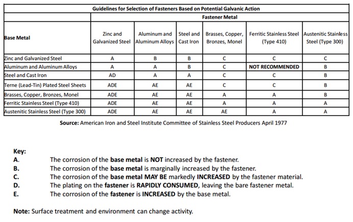
Then see Figure 3 because it gives more information about choices of materials for the fastener and connection materials. Here the probable results of galvanic corrosion to the fastener and base metals are described for various common combinations of common construction materials. It will help to explain which parts of the connection will be affected by galvanic corrosion and how severe the corrosion is likely to be.

Figure 3. Guidelines for selecting fasteners based on potential galvanic action (Stuart, D.M. 2013. Dissimilar Materials. PDHonline course S118. Fairfax, VA)

We know that you have many challenges when designing fastener connections, and it is our hope that this discussion helps you make informed choices when fastening dissimilar materials. Remember: Galvanic corrosion happens! Let us know if you have any comments.

Pile Construction Fasteners – New and Expanded Applications

The majority of Simpson Strong-Tie fasteners are used to secure small, solid-sawn lumber and engineered wood members. However, there is a segment in the construction world where large piles are the norm. Pile framing is common in piers along the coast, elevated houses along the beach, and docks and boardwalks.

While the term “pile” is generic, the piles themselves are not generic. They come in both square and round shapes, as well as an array of sizes, and they vary greatly based on region. The most common pile sizes are 8 inches, 10 inches, and 12 inches, square and round, but they can be found in other sizes. The 8-inch and 10-inch round piles are usually supplied in their natural shape, while 12-inch round piles are often shaped to ensure a consistent diameter and straightness. All piles are preservative-treated.

Historically, the attachment of framing to piles has been done with bolts. This is a very labor-intensive method of construction, but for many years there was no viable fastener alternative. Two years ago, however, Simpson Strong-Tie introduced a new screw, the Strong-Drive® SDWH Timber-Hex HDG screw (SDWH27G), specifically designed for pile- framing construction needs. It can be installed without predrilling and is hot-dip galvanized (ASTM A153, Class C) for exterior applications.

Figure 1 – SDWH27G Lengths

Simpson Strong-Tie tested a number of different pile-framing connections that can be made with the SDWH27G screw. This blog post will highlight some of the tested connections. More information can be found in the following three documents on our website:

  • The flier for the SDWH Timber-Hex HDG screw: F-FSDWHHDG14 found here.
  • The engineering letter for Square Piles found here.
  • The engineering letter for Round Piles found here.

The flier provides product information, and the engineering letters include dimensional details for common pile-framing connections that were tested.

Piles are typically notched or coped to receive a horizontal framing member called a “stringer.” The coped shoulder provides bearing for the stringer and serves as a means of transferring gravity load to the pile. The SDWH27G can be used to fasten framing to coped and non-coped round and square piles.

The connections that we tested can be put into four general groups that include both round and square piles:

  • Two-side framing on coped and non-coped piles
  • One–side framing on coped and non-coped piles
  • Corner framing on coped piles
  • Bracing connections

Additionally, the testing program included four different framing materials in several thicknesses and depths:

  • Glulam
  • Parallam
  • Sawn lumber
  • LSL/LVL

The total testing program included more than 50 connection conditions that represented pile shape and size, framing material and thickness and framing orientation and details. We assigned allowable uplift and lateral properties to the tested connections using the analysis methods of ICC-ES AC13. Figures 2 and 3 show some of the tested assemblies.

Figure 2 – Uplift Test of a 10" Coped Round Pile with a 3-2x10 SYP Stringer
Figure 2 – Uplift Test of a 10″ Coped Round Pile with a 3-2×10 SYP Stringer
Figure 3 – Lateral Test of an 8" Coped Square Pile with a 3.125" Glulam Stringer
Figure 3 – Lateral Test of an 8″ Coped Square Pile with a 3.125″ Glulam Stringer

Figures 4 through 9 illustrate some of the connections and details that are presented in the flier and engineering letters.

Some elements of practice are important to the design of pile-framing connections. Some of the basic practices include:

  • For coped connections, the coped section shall not be more than 50% of the cross-section.
  • For coped connections, the coped shoulder should be as wide as the framing member(s).
  • Fastener spacing is critical to the capacity of the connection.
  • When installing fasteners from two directions, lay out the fasteners so that they do not intersect.
Figure 4 – Square and Round Two-Sided Stringers
Figure 5 – Single-Side Stringer with Notched Pile
Figure 6 – Single-Side Stringer with Unnotched Pile
Figure 7 – Round Pile Corner Condition
Figure 8 – Square Pile Corner Condition

In many cases, pile-framing connections use angled braces for extra lateral support. The SDWH27G can be used in these cases too.

Figure 9 – Braced Condition

In the flier and engineering letters previously referenced, you will find allowable loads and specific fastener specifications for many combinations of stringer and pile types and sizes.

What have you seen in your area? Let us know – perhaps we can add your conditions to our list.


FRP Concrete Strengthening – Five Case Studies

Fiber-reinforced polymer (FRP) composite systems can be used to strengthen walls, slabs and other concrete or masonry members in buildings and other structures. The case studies below show ways in which Composite Strengthening Systems™ (CSS) provide valuable solutions for strengthening buildings and other structures for our customers.

Residential Project in San Francisco

The homeowner for this project wanted to repair some spalling concrete on his concrete piers and also wrap the piers with FRP. We worked with the contractor and homeowner to design a cost-effective solution. This was a successful project for all involved, since the alternative was to jacket the piers with costly and unsightly steel jackets.

residential-project-san-francisco
Materials: CSS-CUCF Carbon Fabric, CSS-ES Epoxy Saturant & Primer

School Project in Argentina

The goal of the project was to analyze a standard design of approximately 400 schools in Argentina that were built in the 1980s and to make recommendations to retrofit the structures to meet current seismic code requirements.  On analysis, it was found that columns were in need of shear reinforcement for the schools to meet the new seismic requirements.

Materials: CSS-UCF Carbon Fabric, CSS-CA Carbon FRP Anchors, CSS-ES Epoxy Saturant & Primer

Hospital Project in Butler, PA

The Engineer of Record on this project wanted to provide continuity across the slab construction joints, something which the existing rebar did not provide. We provided a design of Near-Surface-Mounted (NSM) laminates, which are installed in saw-cut grooves in the top of the concrete slab. This installation allows a flush finished surface, important for allowing the floor finishes to be installed on the slab.

Materials:CSS-CUCL Carbon Precured Laminate, CSS-EP Epoxy Paste & Filler
Materials: CSS-CUCL Carbon Precured Laminate, CSS-EP Epoxy Paste & Filler

Silo Project in Garden City, IA

The concrete silos on this project had spalling at the top portion, which caused a hazard at this site. After repairing the concrete, we provided a ring of carbon fabric to assist in keeping the top concrete of the silos solid for years to come.

Materials:CSS-CUCF Carbon Fabric, CSS-ES Epoxy Saturant & Primer
Materials: CSS-CUCF Carbon Fabric, CSS-ES Epoxy Saturant & Primer

Bridge Project in MN

MNDOT wanted to gain experience working with our CSS products on one of their bridges. We worked with their staff to design several types of strengthening solutions for bridge pier caps and columns. We then provided onsite installation training for the MNDOT maintenance staff to install the FRP products on the bridge.

Materials:CSS-CUCF Carbon Fabric CSS-CUGF E-glass Fabric CSS-ES Epoxy Saturant & Primer CSS-EP Epoxy Paste & Primer frp concrete strengthening
Materials: CSS-CUCF Carbon Fabric, CSS-CUGF E-glass Fabric, CSS-ES Epoxy Saturant & Primer, CSS-EP Epoxy Paste & Primer

We recognize that specifying Simpson Strong-Tie® Composite Strengthening Systems™ is unlike choosing any other product we offer. Leverage our expertise to help with your FRP strengthening designs. Our experienced technical representatives and licensed professional engineers provide complimentary design services and support – serving as your partner throughout the entire project cycle. Since no two buildings are alike, each project is optimally designed to the Designer’s individual specifications. Our pledge is to address your specific condition with a complete strengthening plan tailored to your needs, while minimizing downtime or loss of use, at the lowest possible installed cost.

silos

Your Partner During the Project Design Phase 

During the Designer’s initial evaluation or preparation of the construction documents, Simpson Strong-Tie can be contacted to help create the most cost-effective customized solution. These plans include detailed design calculations for each strengthening requirement and design drawings with all the necessary details to install the CSS system. Simpson Strong-Tie Engineering Services will work closely with the Design Engineer to provide all the necessary information required to design the system.

Why Use Our Design Services?

  • Assess feasibility studies to ensure suitable solutions to your application
  • Receive customized FRP strengthening solutions
  • Work with our trained contractor partners to provide rough-order-of-magnitude (ROM) budget estimates
  • Collaborate during the project design phase
  • Receive a full set of drawings and calculations to add to your submittal
  • Maintain the flexibility to provide the most cost-effective solution for your project
  • Gain trusted technical expertise in critical FRP design considerations

css_dwg_pkg


Learn more: Webinar – Introducing Fabric-Reinforced Cementitious Matrix (FRCM)

In this free webinar we dive into some very important considerations including the latest industry standards, material properties and key governing limits when designing with FRCM.

Continuing education credits will be offered for this webinar.
Participants can earn one professional development hour (PDH) or 0.1 continuing education unit (CEU).


For complete information regarding specific products suitable to your unique situation or condition, please visit strongtie.com/css or call your local Simpson Strong-Tie RPS specialist at (800) 999-5099.


New LSSJ Hanger Strengthens Jack Rafter Connections

When our company is considering a new or improved product, we like to start out by talking to our customers first. That’s what we did recently with a connector improvement project for attaching jack rafter hangers in roof framing – and we got lots of feedback!

We heard from installers that they really wanted a hanger that could be easily adjusted in the field for different slopes and skews. We were asked whether we could design a hanger that could be installed after the rafters were already tacked into place to support construction sequencing and retrofit applications. Also, having a hanger that could be installed from one side was a popular time-saving request.

Our Engineering innovation team took all this feedback and closely evaluated our current selection of hangers. After much consideration, the team decided that rather than adapt one of our existing hangers, they would try to  come up with an all-new design that would satisfy our customers’ most pressing needs.

After months of designing and testing prototypes in the lab and in field trials, the answer was yes. The result is our new LSSJ field-adjustable jack hanger. It’s an innovative field-slopeable and field-skewable hanger that features a versatile hinged seat. This new design allows it to be adjusted to typical rafter slopes, with a max slope of 12:12 up or down.

What is a jack hanger and why does it provide a better connection than nails alone? 

There are two basic types of wood roof construction: framed roof construction (stick framing) as shown above, and truss assembly. The main difference is that stick assembly takes place onsite, while trusses are prefabricated and ready to place. In the United States, the number of truss-built roofs versus stick-frame roofs is about two to one. The LSSJ jack hanger is used for stick-frame construction and provides a connection between the jack rafter to either the hip rafter or the valley rafter as shown below.

The LSSU hanger connects the jack rafter to the hip rafter
The LSSJ hanger connects the jack rafter to the hip rafter

Connecting a 2X jack rafter to a hip is hardly new. The hardest thing is making a good compound miter cut – something an experienced framer can figure out (and most engineers marvel at). In many parts of the country, these are simply face-nailed into place.  Often there isn’t a lot of engineering that goes into that connection.  However, a closer look raises a couple of questions.

Random Nail Placement

Where exactly are those nails going? When there’s no seat support for the rafter, the allowable shear is reduced per the NDS depending on where the lowest nail on the rafter is. This is based on the split that develops at the lowest fastener. The LSSJ provides a partial seat which not only meets the bearing requirement of section R802.6 of the IRC but also delays the type of splitting found in a nailed-only connection.

Consistent Nail Placement

The LSSJ conforms to the bottom of the jack rafter slope and ensures consistent nail placement on both the rafter and the hip.  Consistent nail placement promotes consistent performance based on testing (or as consistent as wood gets)!  The highest nail on the hip is located near the neutral axis if the hip is one size deeper than the rafter.  This assures that not all the load is focused at the bottom of the hip.

A Closer Look at the LSSJ Jack Hanger

Some of our customers may be familiar with our current product, the LSSU, which is used for the same connection. Here’s a closer look at the improvements that the LSSJ offers.

LSSU and LSSJ
LSSU and LSSJ
lssu-lssj-installation
LSSU and LSSJ Installation
lssu-lssj-Skewing
LSSU and LSSJ Skewing

You can see the differences and improvements just by looking at these hangers, installations and load tables. Here’s a different way of showing the advances and benefits of the LSSJ:

LSSJ Improvements
LSSJ Improvements

One of the greatest improvements is the fact that there are fewer nails to install in the LSSJ, and the loads are very similar if not better.

In addition to the LSSJ, Simpson Strong-Tie offers a full line of connectors for wood-framed sloped roofs, including:


We look forward to hearing from you about our newest innovation. For more information about the LSSJ hanger, please see strongtie.com.

Cold-Formed Steel Curtain-Wall Systems

In August 2012, Simpson Strong-Tie launched a comprehensive, innovative solution for curtain-wall framing. Our lead engineer for developing our line of connectors for curtain-wall construction explains the purpose of the curtain wall with the illustrations below.

steel-stud-framingFirst, curtain walls are not what you put up if you shared a room with your brother and sister when you were growing up. When I first learned about the use of cold-formed steel curtain walls, I laughed and thought: “Gosh, how useful this would be for someone growing up with 5 siblings in one bedroom!” I have always enjoyed the sense of humor that our engineers use to help explain technical topics.

Curtain walls can be described as exterior building walls with the primary purpose of protecting the interior building against the exterior weather and natural phenomena such as sun exposure, temperature changes, earthquakes, rain and wind.

To put it in structural terms, a curtain-wall system consists of non-load-bearing exterior walls that must still carry their own weight. Curtain walls are not part of the primary structural framing for the building, but they typically rely on the primary structural framing for support. Additionally, curtain walls receive wind and seismic loads and transfer these forces to the primary building structure.

Types of Curtain Walls

Glass and cladding curtain walls make up two basic types of curtain-wall systems. Glass curtain-wall systems are usually designed using aluminum-framed walls with in-fills of glass. The cladding curtain wall is a system with back-up framing that is covered in some type of cladding material. The cladding curtain-wall system is the type in which Simpson Strong-Tie products can be used.

mid-rise-buildings-1The back-up framing is the structural element of the curtain-wall system. It is typically constructed with cold-formed steel studs ranging from 31/2″ to 8″ deep, in 33 mil (20 ga.) to 97 mil (12 ga.) steel thicknesses. The framing studs are typically spaced at 16″or 24″ on center. There are many different types of cladding materials. They include, but are not limited to, exterior insulation finish systems (EIFS), glass-fiber-reinforced concrete (GFRC), bricks, metal panels and stone panels.

building-material-examplesDeflection

One essential function of the curtain wall is to allow for relative movement between the curtain-wall system and the main building structure. At first, it was not obvious to me why making this allowance was necessary, but our product development team creatively explained some of the reasons why this is an important must-have feature for curtain walls.

deflection-examplesFirst, the primary building will move up and down as it is loaded and unloaded by the live-load occupancy, similar to beam live-load deflections.

Second, the structure sways and has torsional displacement due to movement from lateral wind or seismic loads.

Third, concrete structures typically encounter creep and shrinkage, and there may be foundation differential settlement or soil compression from high-gravity loads.

Lastly, the temperature differential may cause the building elements to expand and contract, which, again, can result in relative movement between structural elements. This is similar to a bridge’s steel plate expansion joint system.

And if you are a curious designer like me, you probably wonder why the relative vertical moment is so significant in engineering design.

One key reason is to ensure that the curtain walls do not collect gravity loads from the building, so as to prevent overloading and possible failure of the stud framing. In addition, a well-designed curtain-wall system needs to retain the primary structural load path as intended by the building designer.

The other reason is to protect the cladding of the building. If you remember earlier, the cladding material may be marble, granite or natural stones that are often very expensive and heavy. In some cases, the cladding can be one of the most expensive systems in a building. And there are times when it’s much more cost-effective to design for relative movement than it is to over-design structural framing to address the stringent deflection requirements.

Construction Type

Bypass framing is a term that is often used in curtain-wall construction. In this system, the metal studs bypass the floor and hang off the outside edges of the building. You can see from the illustration how the studs run past, or bypass, the edge of the slab. In this case, the studs are supported vertically on the foundation at the bottom, and then run continuously past multiple floor levels.

Picture by Don Allen of Super Stud Building Products.

In steel construction, concrete fill over metal deck is typically constructed with a heavy-gauge bent plate or structural angle. Connectors can attach directly to the steel angle or the web of an edge beam.

Simpson Strong-Tie SCB Bypass slide clip connections.
SSB Bypass Framing Slide-Clip Strut connections.


It may seem that this type of construction is too complex and requires great efforts to detail the many connections needed to hang the curtain wall off the outside of the building. So what are the compelling reasons to choose bypass framing construction?

Bypass framing can accommodate flexibility for the architect. In another words, the bypass configuration easily allows architects to create reveals, set-backs and other architectural features.  Plus, there are fewer joints to detail for movement when stud length can run continuously for several floors.  Another benefit is that the exterior finish can also be installed on a curtain-wall system with a tighter tolerance than the edge of the structure.

One other special bypass framing type is known as ribbon window or spandrel framing. Ribbon windows are a series of windows set side by side to form a continuous band horizontally across a façade. The vertical deflection for this type of bypass framing is typically accommodated at the window head. This type of bypass usually works well for panelized construction.

www.glassmagazine.com

Another common curtain-wall system is infill framing, where the studs run from the top of one floor to the underside of the floor above. Sometimes it’s a challenge to attach bypass framing to the edge of thin concrete slabs. In the following illustration, deflection is designed at the top track of wall panels.

bypass-framing-in-actionIn Part 2 of this blog post series, I will provide more details about how we have innovated products to be used for this application, plus a more comprehensive post about the products we offer and how they are typically used.

In the meantime, you can check out our product offering. Our recent SC slide-clip and FC fixed-clip connectors are designed for high-seismic areas.

I would like to invite you to comment and provide feedback on this topic and tell us whether you’ve had any experience working with a Designer on a CFS curtain-wall project. If you are a Designer who specializes in this discipline, how are you designing curtain-wall systems for seismic forces?


Soft-Story Retrofits Using the New Simpson Strong-Tie Retrofit Design Guide

Thousands of soft-story buildings up and down the West Coast require retrofits to prevent collapse in the event of a major earthquake. Whether the retrofits are mandated by a city ordinance (as in San Francisco, Berkeley and Los Angeles) or are undertaken as voluntary upgrades, the benefits of adding necessary bracing to strengthen the ground story are immense. Simpson Strong-Tie has taken the lead, with our new Soft-Story Retrofit Guide, to provide information that helps engineers find solutions to reinforce soft-story buildings against collapse. We are also providing information on the two methods that can be used for the analysis and design of these soft story retrofits.

soft-story-retrofit-guideAfter the initial information section of the guide, a two-page illustrated spread (pp. 14–15) shows various retrofit products that could be used to retrofit the soft-story structure with reference to the following pages. Three main lateral-force-resisting systems highlighted in this graphic are the Strong Frame® special moment frame (SMF), the new Strong-Wall® wood shearwall, and conventional plywood shearwalls. Individual retrofit components are also shown, such as connection plates and straps for lateral-load transfer, anchors for attachment to the foundation, fasteners and additional products such as the RPBZ retrofit post base and AC post caps for providing a positive connection.

soft-story-product-illustrationTurning the page, you come to the section describing in detail the many benefits of the Strong-Frame special moment frame (SMF) in a retrofit situation. The engineered performance of the SMF provides the additional strength and ductility that the building requires and can be fine-tuned by selecting various combinations of beams, columns, and Yield-Link® structural fuse sizes. A typical retrofit Strong Frame® SMF comes in three complete pieces allowing for the frame to be installed on the interior of the structure in tight quarters. The frame is simply installed using a 100% snug-tight field-bolted installation with no on-site welding or lateral-beam bracing required.

field-installation-beam-to-columnThe next lateral system we focus on is the Strong-Wall® shearwall and the new grade beam solutions offered to reduce the concrete footprint. The new Strong-Wall wood shearwall includes an improved front-access holdown and top-of-wall connection plates for easier installation. Both the Strong Frame SMF and the Strong-Wall wood shearwall have load-drift curves available for use with FEMA P-807. Site-built shearwalls can be installed using retrofit anchor bolts at the mudsill and new holdowns at the shearwall end posts.

strong-wall-wood-shearwall-pushover-curveIn the pages following the lateral systems, various products are shown with tabulated LRFD capacities, whereas ASD capacities are typically provided in the order literature for these products. Both ASD and LRFD capacities have been provided for products with new testing values such as the A35 and L90 angles installed with ⅝”-long SPAX screws into three different common floor sheathing materials, as well as for the new HSLQ heavy-shear transfer angle designed to transfer higher lateral forces directly from 4x blocking to the 4x nailer on the Strong-Frame SMF, even when a shim is used between the floor system and the frame. LRFD capacities are provided in this new Soft-Story Retrofit Guide specifically for use with the FEMA P-807 design methodology. This methodology specifies in section 6.5.1 that:

Load path elements should be designed to develop the full strength and the intended mechanism of the principal wall or frame elements. Therefore, to ensure reliability, appropriate strength reduction factors should be applied to the ultimate strengths of load path elements. Specific criteria may be derived from principles of capacity design or from other codes or standards, such as ASCE/SEI 41 or building code provisions involving the overstrength factor, Ωo.

FEMA P-807 bases the capacity of the retrofit elements on the peak strength. LRFD capacities are provided for various load-path connector products, which can be used to develop the full strength of the lateral-force-resisting element to satisfy this requirement.

typical-a35-hslq412-installationWrapping up, the guide focuses on the various free design tools and resources available for the evaluation, design and detailing of the soft-story structure retrofit. These tools include the Weak Story Tool with Simpson Strong-Tie® Strong Frame® Moment Frames, Design Tutorials for the WST for both San Francisco– and Los Angeles–style buildings, our Soft-Story Retrofit Training Course offering CEUs, Strong Frame Moment Frame Selector Software, Anchor Designer™ Software for ACI 318, ETAG and CSA, and tailored frame solutions using our free engineering services.

soft-story-documentsFor other information regarding soft-story retrofits, refer to previous blogs in “Soft-Story Retrofits,”  “City of San Francisco Implements Soft-Story Retrofit Ordinance,” and “Applying new FEMA P-807 Weak Story Tool to Soft-Story Retrofit.”


How to Pick a Connector Series – Truss Hangers

In our second blog in the “How to Pick a Connector Series,” Randy Shackelford discussed the various considerations involved in selecting a joist hanger. So why is this blog post about truss hangers? A hanger is a hanger, right? Before I moved into the Engineering Department at Simpson Strong-Tie, I was the product manager for our Plated Truss product line. I can assure you that there is a bit more that goes into the selection (and design) of a truss hanger than does into selecting a joist hanger!

Of course, all of the considerations that were covered in the joist hanger blog apply to truss hangers as well. This blog post is going to discuss some additional considerations that come into play in selecting a hanger for a truss rather than a joist, and how some hangers have features designed especially for trusses.

The first (and most obvious) truss-specific consideration is the presence of webs. Because of truss webs, top-flange hangers are not as conducive to truss applications as they are to joist applications. A better alternative for trusses is an adjustable-strap hanger that can be installed as a top-flange hanger or face-mount hanger. Take the THA29, for example, Simpson’s first hanger developed specifically for the truss industry (circa 1984). It can accommodate different girder bottom chord depths, which eliminates the need for multiple SKUs, and the straps can be field-formed over the top of the girder bottom chord to reduce the number of fasteners (just like top-flange hangers). When a web member is in the way of the top-flange installation method, the straps can be attached vertically to the web in a face-mount installation instead.

Typical THA29 Installation

What if the web at that location isn’t vertical? You can still install the strap onto the web, but if any nails land in the joint lines formed by the intersection of the wood members, they cannot be considered effective. Therefore, the hanger allowable load may need to be reduced to account for ineffective header nails. This alternative installation is acceptable for any face-mount hanger located at a panel point as shown in our catalog (see detail below).

hgus2102-installed

Although very versatile, not all adjustable-strap hangers can be installed on all sizes of bottom chords. Our catalog specifies a C-dimension for these hangers, which corresponds to the height of the side-nailing flanges. If that dimension exceeds the height of the bottom chord, then the straps cannot be field-formed as needed for the top-flange installation. And if the hanger isn’t located at a panel point, nailing the straps to any diagonal web that the straps can reach (see photo below) is not an acceptable option!

The wrong hanger selection for the application

Another unique consideration that goes into the selection of a truss hanger is the heel height of the carried truss. A truss with a short heel height installed into a tall hanger will likely leave air (or “daylight,” as I call it) behind a lot of the nail holes running up the side flanges. When nail holes in a hanger have air behind them instead of wood, this equates to a reduction in hanger capacity. So when the carried truss has a heel height that is much less than the depth of the carrying member (and the hanger), it is important to use the appropriate hanger capacity for that condition and not overestimate the hanger’s capacity. Refer to our technical bulletin T-REDHEEL for allowable loads for reduced heel height conditions.

Example of a short heel installed in a tall hanger.

Because trusses are capable of carrying a lot of load –  and producing large reactions –  hangers for truss applications often require larger capacities than joist hangers. Unfortunately, there is only so much capacity that can be achieved from a hanger that fits entirely onto a girder truss bottom chord. Therefore, in order to use our highest load-rated truss hangers, a properly located vertical web is required, and the web must be wide enough for the hanger’s required face fasteners and minimum edge distances. The more capacity that is required, the more fasteners it takes, and the wider the vertical web must be. Our highest-load-rated truss hanger that installs with screws is the HTHGQ. It has a maximum download capacity of 20,735 lb., but it requires a minimum 2×10 vertical web. The THGQ/THGQH series can be installed onto as small as a 2×6 web, but the maximum possible capacity on a 2×6 web is 9,140 lb.

hthgq-installation

In addition to high-capacity hangers, truss applications often require high-capacity skewed hangers. When selecting skewed hangers, it’s important to realize that hangers with custom skew options usually have a reduction that must be applied to the hanger’s 90-degree capacity.  Another important factor that is sometimes overlooked in the selection of skewed hangers is whether the carried member is square-cut or bevel-cut. When the member is square cut – as in the case of trusses – not only does this typically result in a greater reduction in capacity, but some skewed hangers cannot be used at all with square-cut members. For example, the fastener holes on the side flange may not be located far enough away from the header to accommodate square-cut members. See the photo below for an example of what can happen if a skewed hanger that is intended for a bevel-cut member is used for a truss.

Incorrect hanger selection – this skewed hanger requires the carried member to be bevel-cut whereas the truss is square-cut.
Not all skewed hangers can be used with square-cut members (trusses).

As discussed in the previous hanger blog, face-mount hangers offer the advantage of being installed after the joist (or truss) is installed. What if the truss is installed prior to the hanger and a gap exists between the truss and the carrying member? In that case, the best option may be to select a truss hanger that was designed with this type of installation tolerance in mind, the HTU hanger. Other face-mount truss hangers that use double-shear nailing are great when gaps are limited to ⅛” or less, but their capacities take a pretty large hit when the gap exceeds ⅛” (see our previous blog Minding the Gap in Hangers for more information). The HTU was designed to give an allowable load for up to a ½” gap between the end of the truss and the carrying member. In addition, it has built-in nailing options to accommodate short heel heights even in the taller models – definitely a truss hanger!

HTU Hanger
HTU Hanger

Finally, there is one more thing to consider when selecting a face-mount hanger for a truss application, which relates to how tall the carrying member is compared to the hanger. Assuming the bottom of the hanger will be installed flush with the bottom of the girder bottom chord, a hanger that is much shorter than the bottom chord will induce tension perpendicular to the grain in the chord. Due to wood’s inherent weakness in perpendicular-to-grain tension, a hanger that is too short may limit the amount of load that can be transferred– to something less than the hanger’s published allowable load. Therefore, it isn’t enough to check whether the hanger fits on the bottom chord; the hanger must also cover enough depth of the chord to effectively transfer the load (or else the allowable hanger load may need to be reduced to the member’s allowable cross-grain tension limit).

Cross-grain tension is not a truss-specific issue, but because it is an explicit design provision in the truss design standard (TPI 1), it is a necessary consideration to mention in a discussion about truss hanger selection. In fact, proper detailing for cross-grain tension in different wood applications could be a future topic in and of itself.

Add to all this the specialty truss hangers that can carry two, three, four, and even five trusses framing into one location, and it is no wonder that there is an entire section in our catalog that is dedicated to truss hangers. Are there any other truss hanger needs that you would like to discuss? Please let us know in the comments below!


Can Decorative Hardware Add Structural Strength?

At Simpson Strong-Tie, we really try to listen to our customers. Our products are developed with your needs in mind.

Last year, at my daughter’s college orientation, I found myself in an interesting conversation with one of the other parents. It turned out that he owns a deck-building company. When he found out that I’m an engineer at Simpson Strong-Tie, his first question was “why don’t you guys make some nice-looking connections that I can use on my decks?”

Ugly Connector
Ugly Connector

I had to choke back a laugh because that’s exactly what I was working on at the time. What he didn’t mention (but we knew he also needed) were connectors that are fast to install, suitable for outdoor use and structurally rated for engineered designs. We also knew code approval was critical to help building departments approve the designs.

The Outdoor Accents® connectors we designed include some basic T’s, L’s, angles and post bases with a nice architectural feature of decorative edges from our Mission Collection®. The steel has our ZMAX® (G185) galvanizing (which is twice as heavy as our standard G90) to resist corrosion and a black powder-coat finish for aesthetics.

outdoor-accents-group outdoor-accents-strap

But the real innovation is in the fastener. Architectural connectors and big bolts go hand in hand, but big bolts are expensive, time consuming and often structurally unnecessary. To solve the installation issue, we designed a decorative washer that looks like a washer and nut and perfectly fits our SDWS22DBB Structural Wood screw.

stn22-installation-with-sdws

We named it the shear tube nut (STN) because the extended tube increases the shear area in contact with the connector.

shear-tube

Together with the SDWS22DBB screw, this solution looks like a bolted connection but installs with the speed and ease of a self-tapping screw. Structurally as well, the hardware is comparable to a bolted connection with a shear capacity of 470 lb. per fastener when used with metal side plates, i.e., connectors.1  The solution has also been tested and load rated for use directly on wood, so it can be used for a variety of other connections such as joining multi-ply beams, knee braces, etc.

In order to be code approved, the SDWS22DBB screws were tested with and without the STN in both wood-to-wood and metal-to-wood per AC233 Acceptance Criteria for Alternate Dowel-Type Threaded Fasteners. The connectors and fasteners, including STN, were tested as assemblies per ASTM D7147. Code agency reviewers quickly saw the benefits of the design and issued evaluation reports verifying the loads. The Outdoor Accents® connectors and SDWS22DBB screws are recognized under IAPMO UES ER-280 and ER-192, respectively. The smaller APA21 angle uses our new SD10112DBB screw, which is listed in ICC-ES ESR-3046.

My deck-builder friend will be pleased to see the new connectors are now available at select Home Depot stores.

outdoor-accents-project

I can’t wait to see what he thinks of them and to get his ideas for the next big project. How about you?  What would you build with these new architectural products?  Let us know in the comments below.

  1. Ref. IAPMO UES ER-192 Table 6A steel side member DF = 470 lb.; 2015 NDS Table 12B 3 1/2″ main member, 1/2″ bolt, DF perpendicular-to-grain = 510.

Outdoor Accents®

Add Beauty and Strength to Your Custom Outdoor Living Structures.


Designing Gable End Overhangs

It seems that each major hurricane tends to teach those of us in the construction industry some lesson. With Hurricane Andrew, the lessons were the importance of protection from windborne debris, and the importance of proper construction of gable end overhangs.

There are two main areas where gable ends can fail.

Continue Reading

How to Pick a Connector Series – Selecting Fasteners

The parts won’t hold themselves up. They have to be fastened in place.

The previous blog in the How to Pick a Connector Series by Randy Shackelford, on “ Selecting a Joist Hanger,” covered the available Simpson Strong-Tie joist hanger options and how to pick a hanger for your design. This week’s blog focuses on the fasteners recommended for various wood connectors.

For straps, holdowns and other connectors, the first step is to specify a product that meets the load and corrosion resistance requirements. Then, specify fastening that is appropriate. The Wood Construction Connectors catalog, C-C-2015, offers fastener information for every Simpson Strong-Tie connector used in wood construction. If you specify the type and number of fasteners and install them as shown in the catalog, then your installation will get full design values. Many connectors are designed to be installed with either nails or Strong-Drive® SD Connector screws. Some products must be installed with Strong-Drive SDS Heavy-Duty Connector screws. Figure 1 is a snip from page 76 of catalog C-C-2015. Here the face-mount hanger table gives the size and number of nails to be installed in the header and the joist, and the table note defines the nail size terminology. Let’s take a look at the various fasteners used for Simpson Strong-Tie connectors of all varieties.

Figure 1. A snip from the face-mount hangers table showing the size and number of nails to be used in the header and joist. The footnote defines the nail sizes in the table.

Figure 2 shows a scale view of almost all of the fasteners used with connectors. You can find this illustration in the Fastening Systems catalog, C-F-14, and the Wood Construction Connectors catalog, C-C-2015. However, we are continually designing, evaluating and adding new fasteners to use with our connectors. Check our website for the latest and greatest.

Figure 2. Fastener types and sizes specified for Simpson Strong-Tie connectors.

Keep in mind some generalities that are to be considered in every connector fastener specification.

  • Type and size – Be sure to specify the correct type of fastener and size; for nails, that means diameter and length.
  • Do not mix fasteners – Do not combine nails and screws in the same connector unless specifically allowed to do so in the load table.
  • Corrosion resistance – Consider environmental corrosion and galvanic corrosion. For environmental corrosion, specify fasteners that have corrosion resistance similar to the connector; for galvanic corrosion, the fasteners and connector should be galvanically compatible. Figure 3 shows the corrosion resistance recommendations for fasteners and connectors.
Figure 3. Corrosion resistance recommendations.

NAILS

Nail terminology is messy. In a recent Structure Magazine article (July 2016), the author made the point that nail specifications are frequently misinterpreted (or overlooked), and as a result the built system does not have the intended design capacity. In general construction vernacular, specification by penny size identifies only the length. For example, a “10d” specification could be interpreted to mean 10d common – 0.148″ x 3″, 10d box – 0.128″ x 3″, 10d sinker – 0.120″ x 2.875″, or the 10d x 2.5″ – 0.148″ x 2.5″. See NDS-12, Appendix L, Table L4 for the length, nail diameter and head diameter of Common, Box, and Sinker steel wire nails. What if the face-mount hanger needed 0.148”x3” nails to achieve full load, but the face-mount hanger was installed with 0.148″ x2.5″?  In this case, the nail substitution causes a reduction in load capacity of 15%. The load capacity losses would be even greater if 10d sinker or 10d box nails were used. The load adjustment factors for nail substitutions used with face- mount hangers and straight straps are shown in Table 3.

Simpson Strong-Tie nail terminology further complicates nail specification because, in Strong-Tie lingo, the penny reference is to diameter (not to length). This is further reason to write nail specifications in terms of diameter and length.

The best way to prevent mistakes is to specify nails by both length AND diameter.

There are two types of connector nails available, the Strong-Drive® SCNR Ring-Shank Connector nail and the Strong-Drive SCN Smooth-Shank Connector nail. SCN stands for Structural Connector Nails. R would refer to ring- shank nails. Currently most ring-shank connector nails are available in Type 316 stainless steel. Reasons for this are discussed here. The smooth-shank nails are made of carbon steel and either have a hot-dip galvanized (HDG) finish meeting the specifications of ASTM A153, Class D, or have a bright finish. Stainless-steel ring-shank nails are recommended for stainless-steel connectors. Use hot-dip galvanized nails with ZMAX® and HDG connectors. See Table 1 for the nail properties.

Table 1. Simpson Strong-Tie® connector nail terminology decoder. The penny size refers to diameter and “N” indicates a short nail.

Simpson Strong-Tie connector nail specifications include common nails, sinker nails and short nails. Nails used in connectors should always have a full round head and meet the bending yield requirements of ASTM F1667, Table S1. Nails can be driven with a hammer or power-driven. Table 2 shows the Strong-Tie connector nails by catalog name, size and model number.

Table 2. Simpson Strong-Tie® Strong-Drive® SCN and SCNR Connector nails. HDG is hot-dip galvanized per ASTM A153, Class D; EG is electro-galvanized per ASTM B641, Class 1; SS is Type 316 stainless steel; “A” indicates ring-shank. These are collated for power-tool nailing in paper tape (PT).

Remember that connector double-shear nailing should always use full-length common nails. Do not use shorter nails in double-shear conditions.

Table 3 is snipped from the Fastening Systems catalog, and it shows load adjustment factors for optional fasteners used in face-mount hangers and straps.

Table 3. From the Fastening Systems catalog, C-F-14. Load adjustment factors and footnotes.

SD Screws

Figure 4. SD9112 CONNECTOR Screw.

Almost 150 Simpson Strong-Tie connectors can be installed with Simpson Strong-Tie Strong-Drive® SD Connector screws (Figure 4). The shanks of the SD Connector screws are designed to match the fastener holes in Simpson Strong-tie connectors. The screw features, dimensions, strengths and allowable single-fastener properties are given in ICC-ES ESR-3046, and the SD screws have been qualified for use in engineered wood products. See ICC-ES ESR-3096 for code-approved connectors installed with SD screws.

SD screws can make connector and strap installation easier and can also provide some resistance that is needed beyond what might be offered by nails. Ease of installation is sometimes an issue in tight places where it might be much easier to use a screw-driving tool rather than a hammer or a power nailer. Some installations are improved by using screws instead of nails, especially where pulling away from the mounting member is a possible failure mode. For example, joist hangers for a deck need withdrawal resistance to help keep the deck tightly connected to the ledger.

SD screws are available in four sizes as shown in Table 4 below. These screws are mechanically galvanized per ASTM B695, Class 55, and have corrosion-resistance qualifications for use in chemically treated wood for Exposure Conditions 1 and 3 per ICC-ES AC257, which is the acceptance criterion for Corrosion-Resistant Fasteners and Evaluation of Corrosion Effects of Wood Treatment Chemicals. See ICC-ES ESR-3046 for corrosion resistance details. Visit SD Screws in Connectors for a complete list of connectors that can be installed with SD screws.

Table 4. SD Connector Screws.

Here are a few specification and construction tips for SD screws:

  • SD10 screws replace 16d common and N16 nails in face-mount hangers and straps.
  • SD9 screws replace 8d and 10d common and 1-1/2″ size nails and 16d sinker nails (all nails 0.148″ and 0.131″ diameter) in face-mount hangers and straps.
  • When SD screws are to be an alternative to nails, specify and use only SD screws. Other types of screws shall not be substituted.
  • SD screws are required to be installed by turning. Do not drive them with a hammer or palm nailer!
  • SD screws and nails cannot be mixed in the same connector.

SDS Screws

Figure 5. Strong-Drive® SDS HEAVY-DUTY CONNECTOR Screw.

The Simpson Strong-Tie Strong Drive® SDS Heavy-Duty Connector screws are 1/4″ screws with a hex washer head (Figure 5). They are available in nine lengths. Table 5 shows the available SDS screws. SDS Screws are available with a double-barrier coating or in Type 316 stainless steel. These screws can be installed with no predrilling and have been extensively tested in various applications. SDS screws can be used for both interior and exterior applications. See ICC-ES ESR-2236 for dimensions, mechanical properties and single-fastener allowable properties. As shown in the evaluation report, SDS screws are also qualified for use in chemically treated wood. See the evaluation report for particulars. SDS screws also have been qualified for use in engineered wood products.

Table 5. SDS Heavy-Duty Connector Screws.

If you need more information about the nails and screws recommended for use with Simpson Strong-Tie connectors, visit strongtie.com and see the appropriate catalog, flier or engineering letter. Remember, your choice of fasteners affects the load capacity of your connections.

Let us know if you have any comments on Simpson Strong-Tie fasteners for straps, holdowns and other connectors.