The Great ShakeOut Earthquake Drill is an annual opportunity for people in homes, schools and organizations to practice what to do during earthquakes and improve their preparedness. In a post I wrote last October about the Great ShakeOut, I reminisced about the first earthquake I had to stop, drop and cover for – the Livermore earthquake in January, 1980. This year got me thinking about how our evacuation drills work.
At Simpson Strong-Tie, we use the annual Great ShakeOut drill to practice our building evacuation procedures. Evacuation drills are simple in concept – alarms go off and you exit the building. We have volunteer safety wardens in different departments who confirm that everyone actually leaves their offices. There are always a few people who want to stay inside and finish up a blog post. Once the building is empty and we have all met up in the designated meeting area, we do a roll call and wait for the all-clear to get back to work.
Several years ago the alarms went off. While waiting for the drill to end, we were concerned to see fire fighters arrive and rush into the building. Realizing this was not a drill, there were some tense moments of waiting. The fire chief and our president eventually walked out of the building and our president was yelling for one of our engineers. Turns out the engineer (who shall remain nameless) was cooking a chicken for lunch. Yes, a whole chicken. The chicken didn’t make it – I’m not sure what the guilty engineer had for lunch afterwards. At least we received extra evacuation practice that year. We aren’t allowed to cook whole chickens in the kitchen anymore.
Simpson Strong-Tie is helping increase awareness about earthquake safety and encouraging our customers to participate in the Great ShakeOut, which takes place next Thursday on October 20. It’s the largest earthquake drill in the world. More than 43 million people around the world have already registered on the site.
On October 20, from noon to 2:00 p.m. (PST), earthquake preparedness experts from the Washington Emergency Management Division and FEMA will join scientists with the Washington Department of Natural Resources and the Pacific Northwest Seismic Network for a Reddit Ask Me Anything – an online Q&A. Our very own Emory Montague will be answering questions. The public is invited to ask questions here. (Just remember that this thread opens the day before the event and not sooner.)
We’re also providing resources on how to retrofit homes and buildings, and have information for engineers here and for homeowners here.
Earthquake risk is not just a California issue. According to the USGS, structures in 42 of 50 states are at risk for seismic damage. As many of you know, we have done a considerable amount of earthquake research, and are committed to helping our customers build safer, stronger homes and buildings. We continue to conduct extensive testing at our state-of-the-art Tye Gilb lab in Stockton, California. We have also worked with the City of San Francisco to offer education and retrofit solutions to address their mandatory soft-story building retrofit ordinance and have created a section on our website to give building owners and engineers information to help them meet the requirements of the ordinance.
Last year, Tim Kaucher, our Southwestern regional Engineering Manager, wrote about the City of Los Angeles’s Seismic Safety Plan in this post. Since that time, the City of Los Angeles has put that plan into action by adopting mandatory retrofit ordinances for both soft-story buildings and non-ductile concrete buildings. Fortunately, California has not had a damaging earthquake for some time now. As a structural engineer, I find it encouraging to see government policy makers resist complacency and enact laws to promote public safety.
Participating in the Great ShakeOut Earthquake Drill is a small thing we can all do to make ourselves more prepared for an earthquake. If your office hasn’t signed up for the Great ShakeOut Earthquake Drill, we encourage you to visit shakeout.org and do so now.


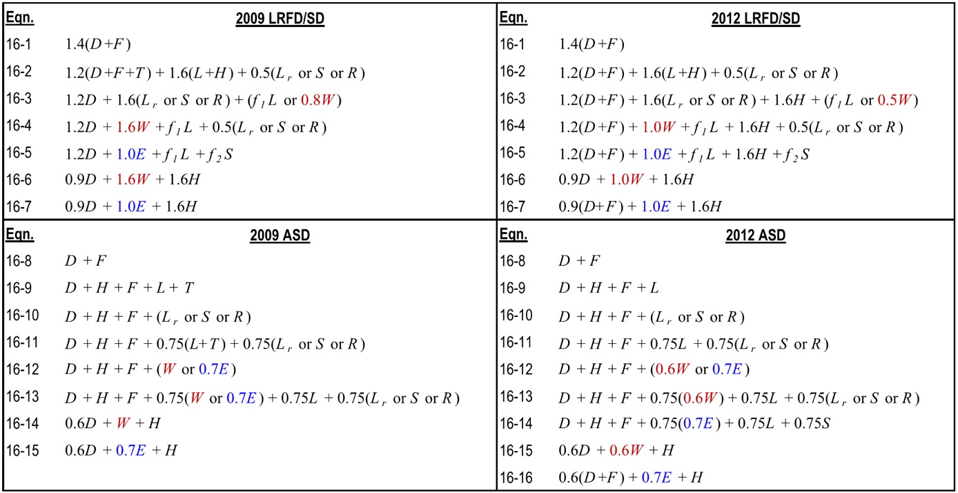
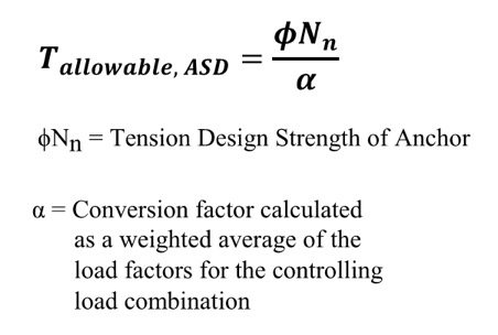 So what do you do now? Well, there is some guidance provided by ICC-ES for manufacturers to convert calculated SD capacities to ASD allowable load values. Since there is no conversion procedure stated in the IBC or referenced standards, designers may want to use this generally accepted method for converting anchor capacities designed using ACI 318. ICC-ES acceptance criteria for post-installed mechanical and adhesive anchors (AC193 and AC308) and cast-in-place steel connectors and proprietary bolts (AC398 and AC399) outline a procedure to convert LRFD capacities to ASD using a weighted average for the governing LRFD/SD load combination. So if the governing load combination for this anchor was 1.2D + 1.6L and the dead load was 1,000 pounds and the live load was 4,000, then the conversion factor would be (1.2)(0.2) + (1.6)(0.8) = 1.52 (keep in mind that the LRFD/SD capacity is divided by the conversion factor in the ICC-ES equation shown here for tension).