Connectors and Fasteners in Fire-Retardant-Treated Wood

In any given year, Simpson Strong-Tie fields several questions about the use of our connectors and fasteners with pressure-treated fire-retardant wood products. Most often asked is whether this application meets the building code requirements for Type III construction, and whether there is a legitimate concern about corrosion. While there haven’t been any specific discussions on this topic in the SE Blog, there have been related discussions surrounding sources of corrosion, such as: Corrosion: The Issues, Code Requirements, Research and Solutions, Corrosion in Coastal Environments, Deck Fasteners – Deck Board to Framing Attachments. This post will explore several resources that we hope will enable you to make an informed decision about which type of pressure-treated Fire-Retardant-Treated Wood (FRTW) to choose for use with steel fasteners and connectors.

One factor contributing to the frequency of these questions is the increased height of buildings now being constructed. With increased height, there is a requirement for increased fire rating. To meet the minimum fire rating for taller buildings, the building code requires noncombustible construction for the exterior walls. As an exception to using noncombustible construction, the 2015 International Building Code (IBC®) section 602.3 allows the use of fire-retardant wood framing complying with IBC section 2303.2. This allows the use of wood-framed construction where noncombustible materials would otherwise be required.

In the 2009 IBC, Section 2304.9.5, “Fasteners in preservative-treated and fire-retardant-treated wood,” was revised to include many subsections (2304.9.5.1 through 2304.9.5.4) dealing with these wood treatments in various types of environmental applications. Section 2304.9.5.3 addressed the use of FRTW in exterior applications or wet or damp locations, and 2304.9.5.4 addressed FRTW in interior applications. These sections carried over to the 2012 IBC, and were moved to Section 2304.10.5 in the 2015 IBC. FRTW is listed in various other sections within the code. For more information about FRTW within the code (e.g., strength adjustments, testing, wood structural panels, moisture content), the Western Wood Preservers Institute has a couple of documents to consult: 2009 IBC Document and 2013 CBC Document. They also have a number of different links to various wood associations.

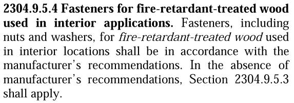
As shown in Figure 1 below, fasteners (including nuts and washers) used with FRTW in exterior conditions or where the wood’s service condition may include wet or damp locations need to be hot-dipped zinc-coated galvanized steel, stainless steel, silicon bronze or copper. This section does permit other fasteners (excluding nails, wood screws, timber rivets and lag screws) to be mechanically galvanized in accordance with ASTM B 695, Class 55 at a minimum. As shown in Figure 2, fasteners (including nuts and washers) used with FRTW in interior conditions need to be in accordance with the manufacturer’s recommendations, or, if no recommendations are present, to comply with 2304.9.5.3.

Figure 1:  Section 2304.9.5.3 of the 2012 IBC (Source ICC)
Figure 1: Section 2304.9.5.3 of the 2012 IBC (Source ICC)
Figure 2:  Section 2304.9.5.4 of the 2012 IBC (Source ICC)
Figure 2: Section 2304.9.5.4 of the 2012 IBC (Source ICC)

In Type III construction where the exterior walls may be FRTW in accordance with 2012 IBC Section 602.3, one question that often comes up is whether the defined “exterior wall” should comply with Section 2304.9.5.3 or 2304.9.5.4. While there are many different views on this point, it is our opinion at Simpson Strong-Tie that Section 2304.9.5.4 would apply to the exterior walls. Since the exterior finishes of the building envelope are intended to protect the wood and components within its cavity from exterior elements such as rain or moisture, the inside of the wall would be dry.

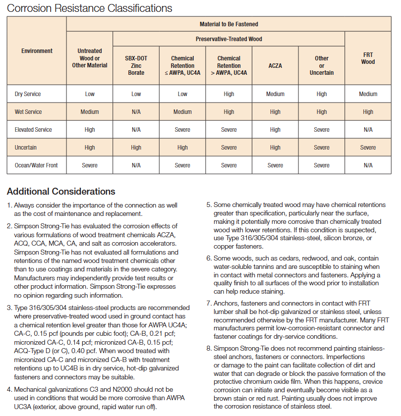
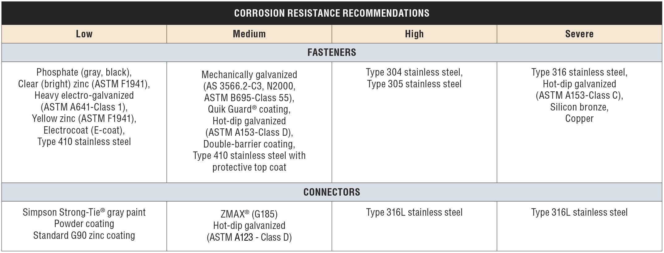
There are many FRTW product choices on the market; take a look at the American Wood Council’s list of treaters. Unlike the preservative-treated wood industry, however, the FRTW industry involves proprietary formulations and retentions. As a result, Simpson Strong-Tie has not evaluated the FRTW products. In our current connector and fastener catalogs, C-C-2015 Wood Connector Construction and C-F-14 Fastening Systems, you will find a newly revised Corrosion Resistance Classifications chart, shown in Figure 3 below, which can be found on page 15 in each catalog. The FRTW classification has been added to the chart in the last column. The corrosion protection recommendations for FRTW in various environmental applications is set to medium or high, corresponding to a number of options for connectors and fasteners as shown in the Corrosion Resistance Recommendations chart, shown in Figure 4. These general guideline recommendations are set to these levels for two reasons: (1) there are unknown variations of chemicals commercially available on the market, and (2) Simpson Strong-Tie has not conducted testing of these treated wood components.

Figure 3: Simpson Strong-Tie Corrosion Resistance Classifications Chart
Figure 4: Simpson Strong-Tie Corrosion Resistance Recommendations Chart

The information above is not the only information readily available. There are many different tests that can be done on FRTW, as noted in the Western Wood Preservers Institute’s document. One such test for corrosion is Military Specification MIL-1914E, which deals with lumber and plywood. Another is AWPA E12-08, Standard Method of Determining Corrosion of Metals in Contact with Treated Wood. Manufacturers of FRTW products who applied for and received an ICC-ES Evaluation Report must submit the results of testing for their specific chemicals in contact with various types of steel. ICC-ES Acceptance Criteria 66 (AC66), the Acceptance Criteria for Fire-Retardant-Treated Wood, requires applicants to submit information regarding the FRTW product in contact with metal. The result is a section published in each manufacturer’s evaluation report (typically Section 3.4) addressing the product use in contact with metal. Many published reports contain similar language, such as “The corrosion rate of aluminum, carbon steel, galvanized steel, copper or red brass in contact with wood is not increased by (name of manufacturer) fire-retardant treatment when the product is used as recommended by the manufacturer.” Structural engineers should check the architect’s specification on this type of material. Product evaluation reports should also be checked to ensure proper specification of hardware and fastener coatings to protect against corrosion. Each evaluation report also contains the applicable strength adjustment factors, which vary from one product to another.

Selecting the proper FRTW product for use in your building is crucial. There are many different options available. Be sure to select a product based on the published information and to communicate that information to the entire design team. Evaluation reports are a great source of information because the independently witnessed testing of manufacturers has been reviewed by the agency reviewing the report. Finally, understanding FRTW chemicals and their behavior when in contact with other building products will ensure expected performance of your structures.

What has been your experience with FRTW? What minimum recommendations do you provide in your construction documents?


From Structural Plans to Truss Designs – Collaborative Effort or Review Nightmare?

In an ideal world, a building is envisioned and a structural engineer begins the structural design. When the decision to use roof trusses is made, a component manufacturer is promptly involved in the design process. Using the loads and design parameters from the structural engineer, the trusses are designed and those designs are provided back to the engineer. The structural engineer then incorporates the truss designs into the building, transfers the loads through the structure and designs all the structural elements, bracing and connections necessary to provide a continuous load path down to the foundation. Finally, working from the complete and detailed plans, the contractor constructs the building flawlessly. Perfection!

But let’s get back to reality, where buildings are often designed and ground broken by the time the trusses are designed. The building Designer creates a roof framing plan to analyze and transfer the loads between the roof system and the rest of the building, and then designs the building (from the top plate down) accordingly. The component manufacturer (CM) eventually gets the plans and uses them to create a truss placement diagram and gather the truss design criteria. The CM then communicates the truss design parameters to the truss design engineer, who designs each of the individual trusses. The CM provides those truss designs and the truss placement diagram back to the building Designer. So far so good, right?

If every building were rectangular with a gable-style roof, this process would be fairly simple and hassle-free. But buildings are often more complicated than that. Roof systems can get very complex, so things don’t always go according to plan…such as when a wall that was intended to be non-load bearing gets used as a bearing location for the trusses; or when the CM moves a girder to a different location that works better for the trusses. Or maybe a truss can’t be designed for the entire span and an additional support is needed. In some cases, the CM may even flip the direction of the trusses completely because it results in a more efficient (lower-cost) truss package – that’s better for the building, right?

Changes during the design process can result in additional labor, material and cost. In today’s fast-tracked world, how can these expenses be avoided? Below are some suggestions from a truss Designer’s perspective.

Know each party’s design responsibilities

This may not seem like it has much to do with minimizing changes during the design process, but some problems arise from the fact that there is not always a common understanding of each party’s responsibilities. One misconception is that truss design engineers design an entire roof system, and they design the roof truss system to work within the framework of the building as set forth in the building structural plans.  This is not true! Truss design engineers design single components, not systems. They do not even see the building Designer’s plans. It is the CM that receives the construction documents to obtain the truss design criteria and requirements. They in turn communicate the truss design parameters to the truss design engineer.

It is also important to understand the role the truss placement diagram plays in the overall process. This is a commonly misunderstood document, because many people think this is an engineered document prepared by the truss design engineer. Not only do truss design engineers not prepare these documents, they do not even review them. Instead, the CM creates the truss placement diagram after reviewing the construction documents. A truss placement diagram is only intended to identify the assumed location for each truss and serve as a truss installation aid. In fact, the truss industry intentionally changed the description of this document at one point from “truss placement plan” to “truss placement diagram” because the word “plan” has a connotation associated with engineering and design, and a truss placement diagram does not involve either of those.

Understanding how the truss industry operates and the responsibilities each party has in the design process will prevent incorrect assumptions from being made. If you find yourself saying, “I’m sure the truss design engineer will check this and take care of it…,” you probably need to think again.

roofpitchtest1L

The clearer the specifications, the better

This may seem obvious, but do the construction documents contain all of the information necessary for the preparation of the truss design drawings? ANSI/TPI 1 specifies the required information in the construction documents (see text box below). Anything less than this information will mean assumptions need to be made during the creation of the truss placement diagram and the design of the trusses. The building Designer can also specify additional requirements to help ensure that the trusses they get are the trusses they want. In short, the more complete, accurate and detailed the construction documents are, the better the design process will be.

Required information in the construction documents (excerpted from ANSI/TPI 1-2014)

Review, review, review

It is the building Designer’s responsibility to review (and approve or reject) both the truss placement diagram and the individual truss design drawings for conformance with the overall building design. As mentioned earlier, the truss design engineer is solely responsible for the design of the individual trusses; they do not review the entire truss system and they do not check to see that the truss placement diagram meets the intent of the framing plan and specifications. Further, the component manufacturer relies on the completeness and accuracy of the information in the construction documents to create the truss placement diagram and to communicate the truss design requirements to the truss design engineer. Therefore, the success of the building’s construction depends on the building Designer’s thorough review of the truss submittal package.

Collaboration is key

Building Designers know what is best for the overall building; component manufacturers know what is best for the trusses. The best-case scenario is when the building gets the best of both. This requires collaboration during the planning stages, so that the strengths of both parties can be utilized to their maximum potential. A building Designer who finds out from the CM what the best setback distance is for a particular hip roof will not only minimize changes to the design downstream, but will also likely end up with a lower-cost building. On the other hand, a building Designer who provides some input into the actual truss designs, such as strategically placed webs in a string of trusses, will end up with a more efficient, permanent bracing plan that can even be included in the original construction documents.

Some may think the answer to this design process challenge is to let the building Designers design the trusses themselves; that all they need is the truss design software and they can design the trusses as part of their building design. But the truss industry knows that truss design software cannot replace the ingenuity and creativity of talented CMs who have a passion for what they do; just the same way that engineering software cannot ever replace an experienced engineer. That is why the truss industry continues to work hard to make it easier to collaborate, in lieu of providing truss design software to people outside of the component manufacturing industry. In this way, everyone’s skill sets can be fully utilized.

What do you think about this challenge? Let us know your thoughts in the comments below!


Strong-Wall Bracing Selector: Bridging the Gap between Engineered Design and Prescriptive Construction

Asking a structural engineer to design wall bracing under the IRC® can be like asking a French pastry chef to bake a cake using Betty Crocker’s Cookbook. The temptation is to toss out the prescriptive IRC recipe and design the house using ASCE 7 loads and the AWC SDPWS shear wall provisions per the IBC®. But if only a portion of the house needs to be engineered, there may be an easier option.

The prescriptive IRC states an IBC engineered design “is permitted for all buildings and structures and parts thereof” but the design must be “compatible with the performance of the conventional framed system.” But how exactly does an IRC braced wall panel perform? The code doesn’t come right out and tell us, but there are two bracing methods that are essentially shear walls masquerading as braced wall panels: Method ABW and Method BV-WSP. Backing into their allowable loads gives us the key to determining equivalence and eliminates the need to develop lateral forces.

But before you can bust out the slide rule and start crunching numbers, you need to figure out how much bracing the prescriptive code requires. We developed our Wall-Bracing-Length Calculator in 2010 to help designers do just that. And last month, we launched our Strong-Wall® Bracing Selector tool to make it easier to specify equivalent solutions for tricky situations.

Strong-Wall Bracing Selector
Wall-Bracing-Length Calculator

You can export the required lengths (and project information) from the Wall-Bracing-Length Calculator directly into the Strong-Wall Bracing Selector or you can manually enter in the required lengths. The selector app will provide a list of Strong-Wall panels that have an equivalent length, evaluate their anchorage loads and return a list of pre-engineered anchor solutions for a variety of foundation types.

If you’re familiar with our Strong-Wall Prescriptive Design Guide (T-SWPDG10), the selector automates this 84-page document in just a few steps. One big upgrade is the ability to select a solution to meet the exact amount of bracing that is required. If you needed 2.8-ft. of wall bracing, you have to round up to the tabulated 4-ft. solutions if you are using the guide, but now you can select a wall solution that is equivalent to 2.8-ft., which might mean a smaller wall width or better anchor options. You also have the ability to save the selector file for later modifications, create a PDF of the job-specific output, or email the PDF directly from the program.

Strong-Wall Prescriptive Design Guide

So next time you get asked to “design” some wall bracing, see if our Wall-Bracing-Length Calculator and Strong-Wall Bracing Selector might save you some time. There is a tutorial and a design example on the Bracing Selector web page, but it’s very easy to use so you may just want to dive right in. I should also point out that the Strong-Wall SB panels have not yet been implemented into the program, but bracing information for them is available on strongtie.com in posted letters for wind (L-L-SWSBWBRCE14), seismic (L-L-SWSBSBRCE14), and seismic with masonry veneer (L-L-SWSBVBRCE14).

Let us know what you think of this new tool in the comments below.


Deck Fasteners – Deck Board to Framing Attachments

When you’re building a deck, it’s important to know the types of fasteners you need to use with the various materials that are available. On this week’s post we explore some deck fastener applications as well as offer suggestions on how to avoid a few common problems. We will address two generic types of deck boards fastened to wood framing: preservative-treated wood and composite decking.

Preservative-Treated Wood Decking

With preservative treated wood, it pays to know the board treatment. Wood is treated with a water-borne treatment chemical (typically micronized copper azole these days) and then it is either sent out wet or it is kiln dried. Wet-treated wood can have a moisture content (MC) greater than 30%. Wood that is subsequently kiln dried to remove excess moisture after the treatment process is labeled Kiln-Dried After Treatment (KDAT) and has a MC of about 15%. Wood deck boards with preservative treatments will be labeled as such regardless of their moisture condition.

The moisture condition of the deck boards determines how best to fasten and space your deck boards. Wet wood will shrink in width and thickness after installation. As a result, you should install these boards butted tight so that gaps will emerge after they dry in place. On the other hand, KDAT wood or wood that is dry should be installed with 1/8” gaps between boards so there is a slight gap after the boards get wet and swell due to rain, ice and snow. Some manufacturers suggest using an 8d common nail for spacing when installing KDAT decking, as seen in the figure below.

Deck Shrinkage and Swelling

Shrinking and swelling of any installed deck board can cause the deck fastener to bend back and forth with the MC cycling. This causes many deck fasteners to break because of the fatigue loading, which can be exacerbated by the brittle steel used in most deck screws.

To combat this problem, Simpson Strong-Tie developed the DSV Wood screw. This screw is specifically designed with increased ductility to handle the bending induced by deck board movement. It is available in a variety of lengths with threads optimized to prevent jacking between the deck board and the framing, ensuring a snug long-lasting connection.

DSV wood screw
DSV wood screw

Composite deck boards are made from a mixture of wood fiber and plastic or are entirely “plastic.” Wood plastic composites and plastic materials exhibit thermal expansion, so they expand and contract in thickness, width and length as a function of temperature and solar heating. Consequently, they typically require a special screw designed for composite decking. Screws for this application will often utilize a two-thread design. The lower thread drives the screw into the framing while the upper thread pulls the loosened composite material back into the hole and holds the deck board tight to the joist. Composite screws also have a cap-style head that covers any residual material left around the screw body and leaves a clean finish. Ductility is important to these screws too.

Given the wide variety of composite deck producers, we designed a screw that works well with all of them. The DCU screw works in all types of composite decking fastened to wood framing.

A note about cellular PVC deck boards: the manufacturers’ recommendation of stainless-steel screws restricts the use of many deck board fasteners. Be sure to read and follow the decking material fastener requirements. Simpson Strong-Tie has a broad offering of painted stainless-steel deck screws available to match PVC deck boards. Find the proper match for your board here.

For other deck fastener applications, including decking fastened to steel framing, and information about other deck fasteners available, see our website product page.

Are there other applications that you want to know about that we didn’t share here? Let us know in the comments below. As always, call us in the Engineering Department if you have questions.


Newest Connector to Satisfy Code

“Does Simpson Strong-Tie write the building code?”

If you work at Simpson Strong-Tie, you get asked this question from time to time when you’re in the field. Over the years, I’ve heard it dozens of times, and because the answer is obviously “no,” it makes you wonder why this belief persists with so many people in the industry. Well, here is my theory: We develop and test products for new code provisions faster than it takes states to adopt the newest codes. So a designer, contractor or building official will often hear about a new Simpson Strong-Tie product or tested application that fills a need before their state building code even defines what that need is. Here are some recent examples:

  • The FWAZ foundation anchor released in 2007 for a 2006 IRC provision that addresses soil pressure loads on basement walls
  • Strong-Drive® SDS screw testing for deck ledgers published in 2008 as alternates to bolts and lags that weren’t prescribed in the IRC until the 2009 edition
  • The DTT2 deck tension tie released in 2009 is used for a 2009 IRC provision that addresses lateral loads on decks
  • BPS ½ -6 bearing plate released in 2011 to address new provisions for shear wall bearing plates in the 2008 SDPWS, which is referenced in the 2009 and 2012 IBC

The latest example is the DTT1Z deck tension tie. Two of our engineers, Randy Shackelford and David Finkenbinder, attended the ICC hearings that resulted in the new 2015 IRC. As soon as a new provision was passed to provide an alternate 750-pound deck lateral load connection (submitted by Washington Assoc. of Building Officials, not Simpson Strong-Tie) we began working on a connector designed to do the job. After several months of R&D, field trials and new tooling, our presses began to stamp out the first production run of the DTT1Z to meet the 2015 IRC provision on December 30, 2014.

DTT1Z Production Run
2015 IRC Detail
2015 IRC Detail

The IRC detail shows an ideal condition where the bottom of the deck joist lines up with the wall plates in the house. We tested this application, but we also wanted to support variations that may come up in the field. The results of this testing appear in our T-C-DECKLAT15 technical bulletin. We also tested the DTT1Z with our Strong-Drive® SDWH Timber-Hex HDG screw and our Titen HD® concrete screw anchor so it can be used in a variety of applications, including prescriptive wall bracing and (very) light shear walls. Many of these applications are covered in the code report (ER130) that was completed just this past week.

2015 IRC Test Setup
Test setup: 2015 IRC detail
Joist Scab Test Setup
Test setup: Blocking attached to side of joist
Joist Blocking Test Setup
Test setup: Blocking running between joists


If you are interested in reading more about the new IRC deck provisions, Randy wrote about them in his Code Corner column in the current Structural Report and David wrote about them in this blog last August.

In case you are wondering how I respond when asked if we write the code, lately I have been answering it with another question: No, but do you know who is responsible for writing the code? My answer to this is “all of us.” If you don’t like what is in there now, work with an association that represents your interests (NCSEA for a lot of us) to submit a code-change proposal, or even submit one yourself. There is no guarantee it will get in, but if it involves a connection, I can guarantee we will get working on it right away!

Let us know if you see a need for a new connection product. If you already have a product idea and would like to work with us to develop it, you can more-formally submit it here.

Steel Strong-Wall® Footings Just got a Little Slimmer!

While 54 inches is a good height and will get you on most amusement park rides, what about this dimension for the width of a footing? We did some tests recently — actually a lot of tests — that answered that question.

Steel Strong-Wall® narrow panels are great for resisting high seismic or wind loads, but due to their narrow widths, their resulting anchor uplift forces can be rather hefty, requiring very large pad footings. How large? For Seismic Design Categories C-F, the largest cracked concrete solution per ACI318-11 Appendix D has a width of 54 inches and an effective embedment depth of 18 inches in order to ensure the anchor remains ductile. The overall length of this footing, as seen in Figure 1, can be up to 132 inches. While purely code driven, these solutions have historically presented challenges in the field. Most concrete contractors have to dig footings this size by hand. This often leads to discussions with their engineers about finding a better solution.

Figure 1:  Slab-on-Grade Installation (Traditional Solution)
Figure 1: Slab-on-Grade Installation (Traditional Solution)

Simpson Strong-Tie has been studying cast-in-place anchorage extensively in recent years. Our research has been featured in a couple of blog posts: The Anchorage to Concrete Challenge – How Do You Meet It? and Podium Anchorage – Structure Magazine. Concrete podium slab anchorage was a multi-year test program that started with grant funding from the Structural Engineers Associations of Northern California for initial concept testing at Scientific Construction Laboratories Inc. and wrapped up with full-scale detailed testing completed at the Simpson Strong-Tie Tye Gilb Laboratory in Stockton, California. This joint venture studied the performance of anchorage reinforcement into thin podium deck slabs (10-14 inch) to resist the high overturning forces of continuous rod systems on 4-5-story mid-rise construction. The testing confirmed the need to comply with Appendix D requirements to prevent plastic hinging at anchor locations. Be on the lookout for an SE Blog post on that topic in the near future. Armed with what we learned, we decided to develop tested anchor reinforcing solutions for the Steel Strong-Wall.

The newly developed anchor reinforcement solutions for grade beams are calculated in accordance with ACI318 Appendix D and tested to validate performance. Anchor reinforcement isn’t a new concept, as it’s been in ACI318 for some time. Essentially, anchor reinforcements transfer load from the anchor bolt to the reinforcing, which restrains the breakout cone from occurring. For the new grade beam details, the additional ties near the anchor are designed to resist the load from the anchor and are developed into the grade beam. The new details offer solutions with widths as narrow as 18 inches when anchor reinforcement is used.

Two details have been developed: one for the larger panels (SSW18, SSW21, SSW24) as shown in Detail 1/SSW1.1, and one for the smaller panels (SSW12, SSW15) as shown in Detail 2/SSW1.1. The difference between the two is the number of anchor reinforcement ties specified in Detail 3/SSW1.1. For SSW18, SSW21 and SSW24 panels (Detail 1/SSW1.1), the total number of reinforcement per anchor is specified. Due to their smaller sizes, the anchor reinforcement ties specified in Detail 2/SSW1.1 for the SSW12 and SSW15 panels are the total required per panel.

Detail 1/SSW1.1
Detail 1/SSW1.1
Detail 2/SSW1.1
Detail 2/SSW1.1
Detail 3/SSW1.1
Detail 3/SSW1.1

Validation Testing

From the concrete podium deck anchorage test program, we discovered that the flexural and shear capacity of the slab is critical to anchor performance and must be designed to exceed the demands created by the attached structure. For grade beams, this also holds true. In wind-load applications, this demand includes the factored demand from the Steel Strong-Wall. In seismic applications, our testing and analysis showed that achieving the anchor performance expected by Appendix D design methodologies requires the concrete member design strength to resist the amplified anchor design demand from Appendix D Section D.3.3.4.3.

Validation testing was conducted to evaluate this concept. The test program consisted of a number of specimens with different configurations, including:

  • Closed tie anchor reinforcement
  • Non-closed tie u-stirrup anchor reinforcement
  • Control specimen without anchor reinforcement

Flexural and shear reinforcement were designed to resist Appendix D amplified anchorage forces and were compared to test beams designed for non-amplified strength level forces. The results of the testing are shown in Figure 2. In the higher Seismic Design Categories (C-F), the anchor assembly must be designed to satisfy Section D.3.3.4.3 in ACI318-11 Appendix D. In accordance with D.3.3.4.3 (a), the concrete breakout strength needs to be greater than 1.2 times the nominal steel strength of the anchor, 1.2NSA. This requires a concrete breakout strength of 87 kips for a Steel Strong-Wall that uses a 1-inch high-strength anchor.

Figure 2: Steel Strong-Wall Grade Beam Testing

Grade beams without the anchor reinforcement detail and with flexural and shear reinforcement designed to the Appendix D amplified anchorage forces performed similar to those with closed-tie anchor reinforcement and flexural and shear reinforcements designed to the non-amplified strength level forces. Both, however, came up short of the necessary forces required by Section D.3.3.4.3 (a). From Test V852, we discovered that even though the flexural and shear reinforcement were designed with the amplified forces, the non-closed tie u-stirrups did not ensure the intended performance. From observation, the u-stirrups do not provide adequate confinement of the concrete and tend to open up under loading conditions, resulting in splitting of the beam at the top as can be seen in the photo.

Test V852: Non-Closed U-Stirrups

Tests W785 and W841 resulted in the best performance. Both test specimens contained flexural and shear reinforcement designed for the amplified forces, as well as closed-ties. Two configurations were tested to study their performance — two piece closed-tie anchor reinforcement in W785 and a single piece closed-tie anchor reinforcement in Test W841. As seen in Figure 2, their performance was very similar, and met the requirements of Section D.3.3.4.3 (a). The closed-ties helped confine the concrete near the top of the beam, allowing the assembly to reach the expected performance load (See the photo below). It’s important to indicate the following specifics in the New Grade Beam Anchor Reinforcement Details:

  • Anchor Reinforcement is #4 closed-ties
  • SSWAB embedment depth is 16″ +/- ½” (as shown in Detail 3/SSW1.1). This is to ensure there is enough development length of the anchor reinforcement on both sides of the theoretical breakout surface as required by ACI318-11 D.5.2.9.
  • The minimum distances from the anchor bolt plate washer to top and bottom of closed tie reinforcement are 13 inches and 5 inches respectively to ensure proper development above and below the concrete breakout cone (refer to Detail 3/SSW1.1).
  • The spacing between the two vertical legs of the anchor reinforcement tie must be 10 inches apart. While this may differ from your shear reinforcement elsewhere in the grade beam, it ensures the reinforcement is located close enough to the anchor and adequate development length is provided.
  • Flexural reinforcement (top and bottom) and shear reinforcement (ties throughout the grade beam length) are per the designer. Simpson Strong-Tie has provided information in Detail 3/SSW1.1 for the applicable minimum LRFD Applied Design Seismic Moment (See Figure 3) to make sure the grade beam design will at least resist the applied anchor forces. Project design loads not related to the Strong-Wall panel also should be considered and could control the grade beam design.
Closed-Tie Anchor Reinforcement
Figure 3: LRFD Applied Design Seismic Moment

Simpson Strong-Tie is interested in hearing your thoughts on the new details. What is your opinion? How have the new details been received on your job sites?

Testing Fasteners for Deck Ledger Connections

This week’s blog post was written by Aram Khachadourian, R&D Engineer for Fastening Systems. Since joining Simpson Strong-Tie 14 years ago, he has designed and tested holdowns, hangers, truss connectors and anchor bolts. He has drafted numerous acceptance criteria as well as quality standards. His current focus is the development, testing and code approval of structural fasteners. Prior to his work at Simpson Strong-Tie, he spent his time designing steel buildings including strip malls, wineries and airplane hangars. Aram graduated from the University of California at Davis with a Civil Engineering degree, and is a registered professional engineer in California.

As we approach the beginning of spring, homeowners across the country are starting to turn their thoughts to the backyard and making plans to add a new deck for summer enjoyment.

As a contractor, designer, or homeowner, you want to know that this new deck will have the structural integrity to stand firm for many years and remain safe for everybody who will use it. While there are many aspects to building a safe, strong deck, today we are focusing on the attachment of the deck ledger to the structure.

Prior to 2009, numerous catastrophic deck failures attributed to improper deck ledger attachments demonstrated the need for building code guidance. A calculated solution was overly conservative because the sheathing layer, typically present between the deck ledger and the structure’s band joist, was considered to be a gap in the connection. A prescriptive approach to deck ledger attachments was finally introduced in the 2009 International Residential Code (IRC). Table R502.2.2.1 provided fastener spacings for ½”-diameter lag screws and bolts. These values were based on testing conducted by researchers at Virginia Tech and Washington State University.

The tests included a variety of band joist types, with pressure-treated Hem-Fir as the deck ledger material. The deck ledger was tested at high moisture content to represent a wet, worst-case field condition. The test assembly had a load bar spanning two joists that were attached to the deck ledger with joist hangers. The ledger was attached through the sheathing to the rim board. Only the rim board was supported by the test frame. The average ultimate load was divided by a factor-of-safety of 3 and then further divided by the load duration coefficient of 1.6 to achieve an allowable load. These values were then applied to a deck live load of 40 psf plus a deck dead load of 10 psf to derive allowable fastener on-center spacings for various joist spans.

When Simpson Strong-Tie began to rate fasteners for ledger connections, we used a similar method of testing and analysis. However, we incorporated a few changes. One of the changes we implemented was a symmetric test set-up.  The original test assembly had a ledger on one end of the joists and a support member as the boundary condition on the other. We put a ledger at each end of the joists so stiffness differences in the supports would not affect the test results. We also chose a larger factor-of-safety of 3.2 (instead of 3.0) to maintain consistency with calculation of fastener allowable loads in other applications. In order to provide our customers with a broader range of construction options, we tested many typical rim board and ledger materials, and we ran tests with single and double ledgers. You can see an example of a typical test set up here:

A typical testing set up
Testing deck ledger connections.

We have tested many Simpson Strong-Tie® Strong-Drive® fasteners for ledger applications including the SDWS Timber screw (SDWS22DB), SDWH Timber-Hex SS screw (SDWH-SS), SDWH Timber-Hex screw (SDWH19DB), and SDS Heavy-Duty Connector screw (SDS). We also have information regarding ledgers attached to studs and ledgers fastened over gypsum board. You can find all of this information in our latest fastener catalog.

One final construction tip – deck ledgers can fail due to cross-grain tension. This occurs when the joist hangers are attached to the deck ledger near the bottom of the ledger, but the fasteners holding the ledger to the building are near the top of the ledger. To prevent cross-grain tension failure, place the joist hangers so at least half of the ledger fasteners are below the joist hanger line.

Take a look through the various ledger options in our fastener catalog, and if we don’t address your condition, let us know. As always, call us in the Engineering Department if you have questions.

Please share your feedback in the comments area below.

Part II: Tensile Performance of Simpson Strong-Tie® SET-XP® Adhesive in Reinforced Brick – Test Results

This post is the second of a two-part series on the results of research on anchorage in reinforced brick. The research was done to shed light on what tensile values can be expected for adhesive anchors. In last week’s post, we covered the test set-up. This week, we’re taking a look at our results and findings.Continue Reading

Part I: Tensile Performance of Simpson Strong-Tie® SET-XP Adhesive in Reinforced Brick: Test Set Up

Guest blogger Jason Oakley, field engineer

This week’s blog post is written by Jason Oakley. Jason is a California registered professional engineer who graduated from UCSD in 1997 with a degree in Structural Engineering and earned his MBA from Cal State Fullerton in 2013. He is a field engineer for Simpson Strong-Tie who has specialized in anchor systems for more than 12 years. He also covers concrete repair and Fiber-Reinforced Polymer (FRP) systems. His territory includes Southern California, Hawaii and Guam.

This post is Part I of a two-part series. In this post, we’ll cover the test set-up and next week in Part II, we’ll take a look at our results and findings.

More than half a century ago, reinforced brick was a fairly common construction material used in buildings located in Southern California and probably elsewhere in the U.S. Reinforced brick can be found in schools, universities, and office buildings that still stand today. This material should not be confused with unreinforced brick masonry (URM) that is also composed of bricks but is structurally inferior to reinforced brick. Engineers are often called to look at existing reinforced brick structures to recommend retrofit schemes that, for example, might strengthen the out-of-plane wall anchorage between the roof (or floor) and wall to improve building performance during an earthquake. Yet, limited or no information exists on the performance of adhesive anchors in this base material. This series of posts shares the results of research on anchorage in reinforced brick in hopes of shedding light on what tensile values can be expected for adhesive anchors, including any important findings encountered during installation and testing.Continue Reading

More Fun with Testing

A couple of years back, I did a blog post with a video of a bowling ball exploding. It’s a fun test to show guests who visit our connector lab. Of course, we also do a joist hanger or holdown test to demonstrate a real test used to load rate our products. The problem is some of our tests just aren’t too exciting to the general population. It’s a bit anticlimactic when the wood slowly crushes or the fasteners withdraw until the test specimen just can’t take any load. But bowling balls explode, and explode fast!

In the last couple of months, our connector test lab ran a number of built-up post compression tests. We were looking for data to compare the performance of built-up posts whose members were fastened with connectors (nails, screws, or bolts) to posts that were glued together.

Southern Pine Built Up Setup
Southern Pine Built-up Setup


Southern Pine Built Up Failure
Southern Pine Built-up Failure


Spruce-Pine-Fir 2x6 Built Up Post
Spruce-Pine-Fir 2×6 Built-up Post


Spruce-Pine-Fir 2x4 Built Up
Spruce-Pine-Fir 2×4 Built-up Post

Our test presses have compression capacities ranging from 100 kips to 200 kips. While we have tested some really heavy connectors, most of our tests are under 50 kips ultimate load. The built-up post testing was exciting to watch as loads got as high as 180 kips and had some very dramatic failures. More fun than the bowling balls, but a little more difficult to contain the explosions.

I have no numbers to share from this testing, as design procedures exist in the code for built-up posts. A few non-technical things we learned from doing this built-up post testing include:

  • Short posts can take a lot of load
  • Regular wood glue requires careful application to get good bond over the full area of a board
  • We haven’t mastered glue application
  • Posts can explode
  • Heavy steel plates go flying when posts explode

Not scientific, but fun to watch. The videos were captured on an iPhone by R&D Lab Testing Technician Steve Ziagos. Steve also blogs about Do-It-Yourself projects on our DIY Done Right blog. Enjoy the video.