According to the Greek philosopher Heraclitus, “The only constant in life is change.”
When the latest Wood Construction Connectors catalog (C-C-2019) was published, my colleague, Paul McEntee, PE authored an excellent blog post to announce some big changes within the catalog. He shared that Simpson Strong-Tie® was the first in the industry with updated connector allowable load tables to meet the new ASTM test standards required by the 2015 and 2018 International Building Code® (IBC®). It was one of those rare times where being first didn’t exactly feel like winning.
The Simpson Strong-Tie® 2019–2020 Wood Construction Connectors catalog is the first in the industry with updated connector allowable load tables to meet the new ASTM test standards required by the 2015 and 2018 International Building Code® (IBC®). It is designed to assist engineers, architects, Designers and contractors in selecting the right products for improved performance, efficiency and productivity. This blog post provides in-depth background about how we re-evaluated our connectors to meet the new standards. Continue Reading
With the use of engineering software tools, structural engineers can design buildings faster and more efficiently than ever before. In this blog post, Clifton Melcher, P.E., a senior project manager for cold-formed steel connectors, discusses the various enhancements included in version 2.5 of Simpson Strong-Tie® CFS Designer™ software. Continue Reading
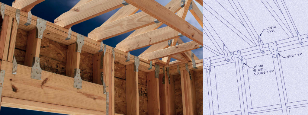
Although truss-designed roofs are predominant throughout most of the residential construction industry, there are regions where building with stick-frame roofs is still common. In this post, Randy Shackelford discusses some design choices available to stick-frame builders, the challenges they pose, and the solutions offered by the Simpson Strong-Tie® connector system for stick-frame roofing. The post will also discuss some changes in the 2021 IRC that affect construction of stick-frame roofs.
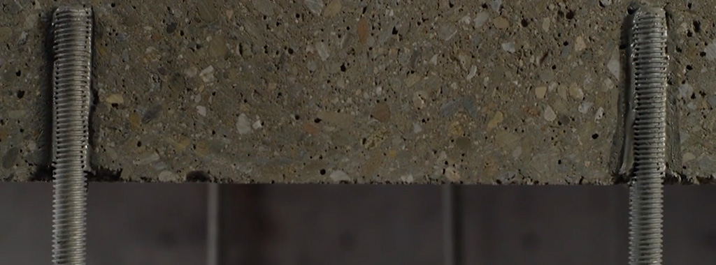
Designing post-installed anchorage near a concrete edge is challenging, especially since the ACI provisions for cracked-concrete anchorage went into effect. In the following post, one of our field engineers, Jason Oakley, P.E., explains how SET-3G™ and Anchor Designer™ software from Simpson Strong-Tie make it easier to design a ductile anchor solution.
Engineers often provide holdown anchoring solutions near a concrete edge to help prevent overturning of light-frame shear walls during a seismic (or high-wind) event. Sometimes a post-installed anchor must be used if the cast-in-place anchor was mislocated or misinstalled, or is located where a retrofit or addition is needed. Since the cracked-concrete anchorage design provisions went into effect more than a decade ago, it has been challenging for engineers to offer a near-edge post-installed anchoring solution. This is especially true for structures subject to earthquake loads in seismic design category (SDC) C through F. Simpson Strong-Tie’s new SET-3G epoxy is the first anchoring adhesive in the industry to offer exceptionally high bond-strength values that permit ductile anchorage in concrete near an edge. This blog post will cover a specific example that focuses on Chapter 17 of ACI 318-14 to design a threaded rod, anchored with SET-3G adhesive, used to secure a holdown located 1 3/4″ away from a single concrete edge (Figure 1). Continue Reading
When our company is considering a new or improved product, we like to start out by talking to our customers first. That’s what we did recently with a connector improvement project for attaching jack rafter hangers in roof framing – and we got lots of feedback!
We heard from installers that they really wanted a hanger that could be easily adjusted in the field for different slopes and skews. We were asked whether we could design a hanger that could be installed after the rafters were already tacked into place to support construction sequencing and retrofit applications. Also, having a hanger that could be installed from one side was a popular time-saving request.
Our Engineering innovation team took all this feedback and closely evaluated our current selection of hangers. After much consideration, the team decided that rather than adapt one of our existing hangers, they would try to come up with an all-new design that would satisfy our customers’ most pressing needs.
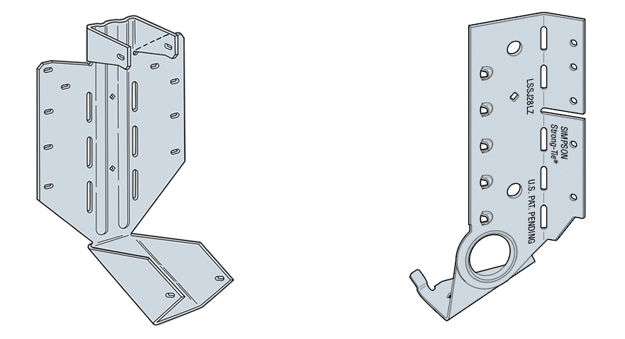
After months of designing and testing prototypes in the lab and in field trials, the answer was yes. The result is our new LSSJ field-adjustable jack hanger. It’s an innovative field-slopeable and field-skewable hanger that features a versatile hinged seat. This new design allows it to be adjusted to typical rafter slopes, with a max slope of 12:12 up or down.
What is a jack hanger and why does it provide a better connection than nails alone?
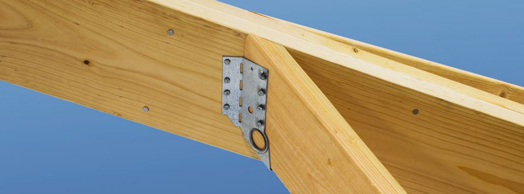
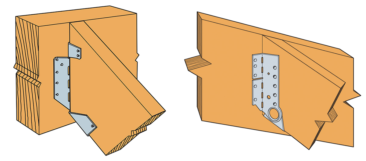
There are two basic types of wood roof construction: framed roof construction (stick framing) as shown above, and truss assembly. The main difference is that stick assembly takes place onsite, while trusses are prefabricated and ready to place. In the United States, the number of truss-built roofs versus stick-frame roofs is about two to one. The LSSJ jack hanger is used for stick-frame construction and provides a connection between the jack rafter to either the hip rafter or the valley rafter as shown below.
The LSSJ hanger connects the jack rafter to the hip rafter
Connecting a 2X jack rafter to a hip is hardly new. The hardest thing is making a good compound miter cut – something an experienced framer can figure out (and most engineers marvel at). In many parts of the country, these are simply face-nailed into place. Often there isn’t a lot of engineering that goes into that connection. However, a closer look raises a couple of questions.
Random Nail Placement
Where exactly are those nails going? When there’s no seat support for the rafter, the allowable shear is reduced per the NDS depending on where the lowest nail on the rafter is. This is based on the split that develops at the lowest fastener. The LSSJ provides a partial seat which not only meets the bearing requirement of section R802.6 of the IRC but also delays the type of splitting found in a nailed-only connection.
Consistent Nail Placement
The LSSJ conforms to the bottom of the jack rafter slope and ensures consistent nail placement on both the rafter and the hip. Consistent nail placement promotes consistent performance based on testing (or as consistent as wood gets)! The highest nail on the hip is located near the neutral axis if the hip is one size deeper than the rafter. This assures that not all the load is focused at the bottom of the hip.
A Closer Look at the LSSJ Jack Hanger
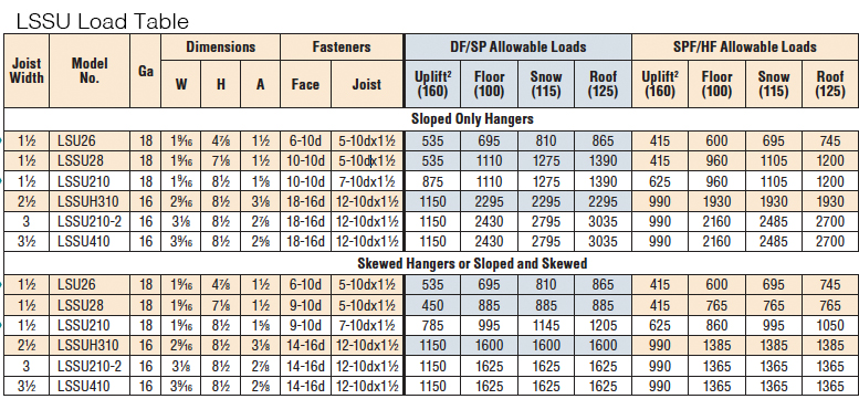
Some of our customers may be familiar with our current product, the LSSU, which is used for the same connection. Here’s a closer look at the improvements that the LSSJ offers.
LSSU and LSSJLSSU and LSSJ InstallationLSSU and LSSJ Skewing
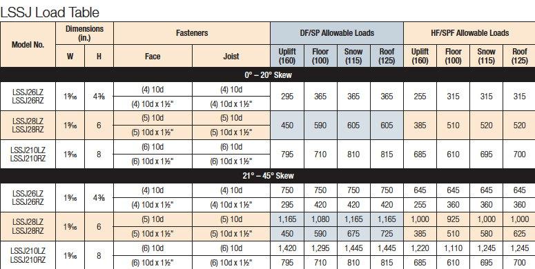
You can see the differences and improvements just by looking at these hangers, installations and load tables. Here’s a different way of showing the advances and benefits of the LSSJ:
LSSJ Improvements
One of the greatest improvements is the fact that there are fewer nails to install in the LSSJ, and the loads are very similar if not better.
In addition to the LSSJ, Simpson Strong-Tie offers a full line of connectors for wood-framed sloped roofs, including:
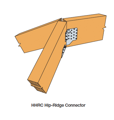
The Hip-Ridge Ride Connector – Is field-slopeable and attaches hip roof beams to the end of a ridge beam.
VPA Variable-Pitch Connector – Offers a versatile solution for attaching rafters to the top plate. It adjusts to accommodate slopes between 3:12 and 12:12. This connector eliminates the need for notched rafters, beveled top plates and top nailing.
HCP Hip Corner Plate connects a rafter or joist to double top plate at a corner.
LRUZ Rafter Hanger – Provides an economical alternative for applications requiring a sloped hanger for rafter-to-ridge connections. Used with solid sawn rafters, this hanger’s design enables it to be installed before or after the rafter is in place.
We look forward to hearing from you about our newest innovation. For more information about the LSSJ hanger, please see strongtie.com.
At Simpson Strong-Tie, we really try to listen to our customers. Our products are developed with your needs in mind.
Last year, at my daughter’s college orientation, I found myself in an interesting conversation with one of the other parents. It turned out that he owns a deck-building company. When he found out that I’m an engineer at Simpson Strong-Tie, his first question was “why don’t you guys make some nice-looking connections that I can use on my decks?”
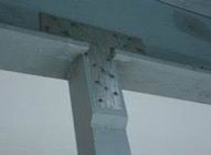
Ugly Connector
I had to choke back a laugh because that’s exactly what I was working on at the time. What he didn’t mention (but we knew he also needed) were connectors that are fast to install, suitable for outdoor use and structurally rated for engineered designs. We also knew code approval was critical to help building departments approve the designs.
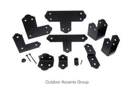
The Outdoor Accents® connectors we designed include some basic T’s, L’s, angles and post bases with a nice architectural feature of decorative edges from our Mission Collection®. The steel has our ZMAX® (G185) galvanizing (which is twice as heavy as our standard G90) to resist corrosion and a black powder-coat finish for aesthetics.
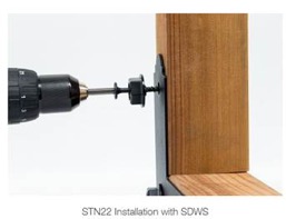
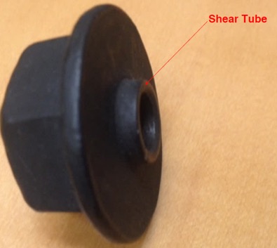
But the real innovation is in the fastener. Architectural connectors and big bolts go hand in hand, but big bolts are expensive, time consuming and often structurally unnecessary. To solve the installation issue, we designed a decorative washer that looks like a washer and nut and perfectly fits our SDWS22DBB Structural Wood screw.
We named it the shear tube nut (STN) because the extended tube increases the shear area in contact with the connector.
Together with the SDWS22DBB screw, this solution looks like a bolted connection but installs with the speed and ease of a self-tapping screw. Structurally as well, the hardware is comparable to a bolted connection with a shear capacity of 470 lb. per fastener when used with metal side plates, i.e., connectors.1 The solution has also been tested and load rated for use directly on wood, so it can be used for a variety of other connections such as joining multi-ply beams, knee braces, etc.
In order to be code approved, the SDWS22DBB screws were tested with and without the STN in both wood-to-wood and metal-to-wood per AC233 Acceptance Criteria for Alternate Dowel-Type Threaded Fasteners. The connectors and fasteners, including STN, were tested as assemblies per ASTM D7147. Code agency reviewers quickly saw the benefits of the design and issued evaluation reports verifying the loads. The Outdoor Accents® connectors and SDWS22DBB screws are recognized under IAPMO UES ER-280 and ER-192, respectively. The smaller APA21 angle uses our new SD10112DBB screw, which is listed in ICC-ES ESR-3046.
My deck-builder friend will be pleased to see the new connectors are now available at select Home Depot stores.
I can’t wait to see what he thinks of them and to get his ideas for the next big project. How about you? What would you build with these new architectural products? Let us know in the comments below.
Ref. IAPMO UES ER-192 Table 6A steel side member DF = 470 lb.; 2015 NDS Table 12B 3 1/2″ main member, 1/2″ bolt, DF perpendicular-to-grain = 510.
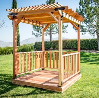
Outdoor Accents®
Add Beauty and Strength to Your Custom Outdoor Living Structures.
The parts won’t hold themselves up. They have to be fastened in place.
The previous blog in the How to Pick a Connector Series by Randy Shackelford, on “ Selecting a Joist Hanger,” covered the available Simpson Strong-Tie joist hanger options and how to pick a hanger for your design. This week’s blog focuses on the fasteners recommended for various wood connectors.
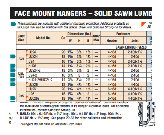
For straps, holdowns and other connectors, the first step is to specify a product that meets the load and corrosion resistance requirements. Then, specify fastening that is appropriate. The Wood Construction Connectors catalog, C-C-2015, offers fastener information for every Simpson Strong-Tie connector used in wood construction. If you specify the type and number of fasteners and install them as shown in the catalog, then your installation will get full design values. Many connectors are designed to be installed with either nails or Strong-Drive® SD Connector screws. Some products must be installed with Strong-Drive SDS Heavy-Duty Connector screws. Figure 1 is a snip from page 76 of catalog C-C-2015. Here the face-mount hanger table gives the size and number of nails to be installed in the header and the joist, and the table note defines the nail size terminology. Let’s take a look at the various fasteners used for Simpson Strong-Tie connectors of all varieties.
Figure 1. A snip from the face-mount hangers table showing the size and number of nails to be used in the header and joist. The footnote defines the nail sizes in the table.
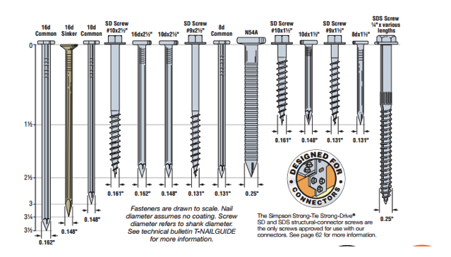
Figure 2 shows a scale view of almost all of the fasteners used with connectors. You can find this illustration in the Fastening Systems catalog, C-F-14, and the Wood Construction Connectors catalog, C-C-2015. However, we are continually designing, evaluating and adding new fasteners to use with our connectors. Check our website for the latest and greatest.
Figure 2. Fastener types and sizes specified for Simpson Strong-Tie connectors.
Keep in mind some generalities that are to be considered in every connector fastener specification.
Type and size – Be sure to specify the correct type of fastener and size; for nails, that means diameter and length.
Do not mix fasteners – Do not combine nails and screws in the same connector unless specifically allowed to do so in the load table.
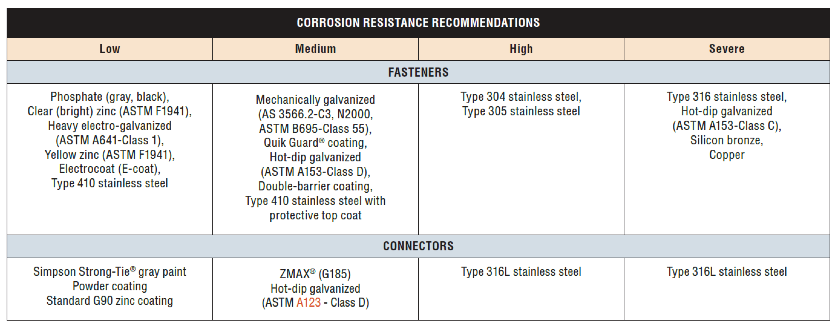
Corrosion resistance – Consider environmental corrosion and galvanic corrosion. For environmental corrosion, specify fasteners that have corrosion resistance similar to the connector; for galvanic corrosion, the fasteners and connector should be galvanically compatible. Figure 3 shows the corrosion resistance recommendations for fasteners and connectors.
Figure 3. Corrosion resistance recommendations.
NAILS
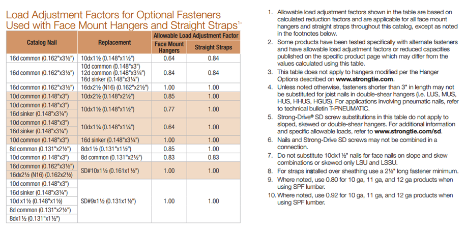
Nail terminology is messy. In a recent Structure Magazine article (July 2016), the author made the point that nail specifications are frequently misinterpreted (or overlooked), and as a result the built system does not have the intended design capacity. In general construction vernacular, specification by penny size identifies only the length. For example, a “10d” specification could be interpreted to mean 10d common – 0.148″ x 3″, 10d box – 0.128″ x 3″, 10d sinker – 0.120″ x 2.875″, or the 10d x 2.5″ – 0.148″ x 2.5″. See NDS-12, Appendix L, Table L4 for the length, nail diameter and head diameter of Common, Box, and Sinker steel wire nails. What if the face-mount hanger needed 0.148”x3” nails to achieve full load, but the face-mount hanger was installed with 0.148″ x2.5″? In this case, the nail substitution causes a reduction in load capacity of 15%. The load capacity losses would be even greater if 10d sinker or 10d box nails were used. The load adjustment factors for nail substitutions used with face- mount hangers and straight straps are shown in Table 3.
Simpson Strong-Tie nail terminology further complicates nail specification because, in Strong-Tie lingo, the penny reference is to diameter (not to length). This is further reason to write nail specifications in terms of diameter and length.
The best way to prevent mistakes is to specify nails by both length AND diameter.
There are two types of connector nails available, the Strong-Drive® SCNR Ring-Shank Connector nail and the Strong-Drive SCN Smooth-Shank Connector nail. SCN stands for Structural Connector Nails. R would refer to ring- shank nails. Currently most ring-shank connector nails are available in Type 316 stainless steel. Reasons for this are discussed here. The smooth-shank nails are made of carbon steel and either have a hot-dip galvanized (HDG) finish meeting the specifications of ASTM A153, Class D, or have a bright finish. Stainless-steel ring-shank nails are recommended for stainless-steel connectors. Use hot-dip galvanized nails with ZMAX® and HDG connectors. See Table 1 for the nail properties.
Table 1. Simpson Strong-Tie® connector nail terminology decoder. The penny size refers to diameter and “N” indicates a short nail.
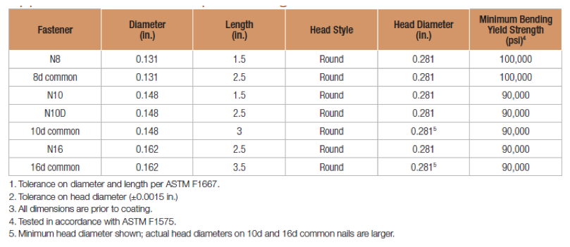
Simpson Strong-Tie connector nail specifications include common nails, sinker nails and short nails. Nails used in connectors should always have a full round head and meet the bending yield requirements of ASTM F1667, Table S1. Nails can be driven with a hammer or power-driven. Table 2 shows the Strong-Tie connector nails by catalog name, size and model number.
Table 2. Simpson Strong-Tie® Strong-Drive® SCN and SCNR Connector nails. HDG is hot-dip galvanized per ASTM A153, Class D; EG is electro-galvanized per ASTM B641, Class 1; SS is Type 316 stainless steel; “A” indicates ring-shank. These are collated for power-tool nailing in paper tape (PT).
Remember that connector double-shear nailing should always use full-length common nails. Do not use shorter nails in double-shear conditions.
Table 3 is snipped from the Fastening Systems catalog, and it shows load adjustment factors for optional fasteners used in face-mount hangers and straps.
Table 3. From the Fastening Systems catalog, C-F-14. Load adjustment factors and footnotes.
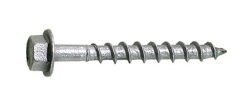
SD Screws
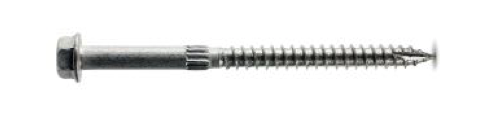
Figure 4. SD9112 CONNECTOR Screw.
Almost 150 Simpson Strong-Tie connectors can be installed with Simpson Strong-Tie Strong-Drive® SD Connector screws (Figure 4). The shanks of the SD Connector screws are designed to match the fastener holes in Simpson Strong-tie connectors. The screw features, dimensions, strengths and allowable single-fastener properties are given in ICC-ES ESR-3046, and the SD screws have been qualified for use in engineered wood products. See ICC-ES ESR-3096 for code-approved connectors installed with SD screws.
SD screws can make connector and strap installation easier and can also provide some resistance that is needed beyond what might be offered by nails. Ease of installation is sometimes an issue in tight places where it might be much easier to use a screw-driving tool rather than a hammer or a power nailer. Some installations are improved by using screws instead of nails, especially where pulling away from the mounting member is a possible failure mode. For example, joist hangers for a deck need withdrawal resistance to help keep the deck tightly connected to the ledger.
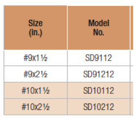
SD screws are available in four sizes as shown in Table 4 below. These screws are mechanically galvanized per ASTM B695, Class 55, and have corrosion-resistance qualifications for use in chemically treated wood for Exposure Conditions 1 and 3 per ICC-ES AC257, which is the acceptance criterion for Corrosion-Resistant Fasteners and Evaluation of Corrosion Effects of Wood Treatment Chemicals. See ICC-ES ESR-3046 for corrosion resistance details. Visit SD Screws in Connectors for a complete list of connectors that can be installed with SD screws.
Table 4. SD Connector Screws.
Here are a few specification and construction tips for SD screws:
SD10 screws replace 16d common and N16 nails in face-mount hangers and straps.
SD9 screws replace 8d and 10d common and 1-1/2″ size nails and 16d sinker nails (all nails 0.148″ and 0.131″ diameter) in face-mount hangers and straps.
When SD screws are to be an alternative to nails, specify and use only SD screws. Other types of screws shall not be substituted.
SD screws are required to be installed by turning. Do not drive them with a hammer or palm nailer!
SD screws and nails cannot be mixed in the same connector.
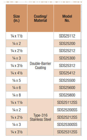
The Simpson Strong-Tie Strong Drive® SDS Heavy-Duty Connector screws are 1/4″ screws with a hex washer head (Figure 5). They are available in nine lengths. Table 5 shows the available SDS screws. SDS Screws are available with a double-barrier coating or in Type 316 stainless steel. These screws can be installed with no predrilling and have been extensively tested in various applications. SDS screws can be used for both interior and exterior applications. See ICC-ES ESR-2236 for dimensions, mechanical properties and single-fastener allowable properties. As shown in the evaluation report, SDS screws are also qualified for use in chemically treated wood. See the evaluation report for particulars. SDS screws also have been qualified for use in engineered wood products.
Table 5. SDS Heavy-Duty Connector Screws.
If you need more information about the nails and screws recommended for use with Simpson Strong-Tie connectors, visit strongtie.comand see the appropriate catalog, flier or engineering letter. Remember, your choice of fasteners affects the load capacity of your connections.
Let us know if you have any comments on Simpson Strong-Tie fasteners for straps, holdowns and other connectors.
Did you know that Simpson Strong-Tie is celebrating its 60th birthday this year? We started out with one punch press and the ability to bend light-gauge steel. Then, one Sunday evening in the summer of 1956, Barclay Simpson’s doorbell rang and a request for our first joist hanger led us into the wood connector business. Since then, we’ve continued to grow that business by focusing on our engineering, research and development efforts. Some might say that nowadays we’re an engineering company that also happens to manufacture products, as evidenced by our focus on developing technology tools over the past few years such as web calculators, an updated website and design software. Our focus on technology, however, is really another aspect of our continued commitment to excellence in manufacturing and our application of the tenets of lean manufacturing.
Many of you may already be familiar with the idea of lean manufacturing made famous by Toyota in the early 2000s, along with the principles of continual improvement and respect for people. The concept of continual improvement is based on the idea that you can always make small changes to improve your processes and products. Although they were established in a manufacturing setting, these ideals ring very true for engineering as well; eliminate steps in your design process that don’t add any value to the final project and always be on the lookout for tools or techniques that can speed up your process. Thinking lean isn’t about cutting corners to get your result faster, it’s about mindfully getting rid of the steps that aren’t helping you and finding better ways of doing everyday tasks.
As structural engineers, we can find ourselves working on a variety of projects that lead us to perform repetitive calculations to check different conditions, such as varying parapet heights on the exterior of a building, or we may find ourselves working with an unfamiliar material, such as light-gauge or cold-formed steel (CFS), where we have to take some time away from design to review reference materials such as AISI S200-12 North American Standard for Cold-Formed Steel Framing. Wouldn’t it be great if there were a design tool that could help you complete your light-gauge projects more quickly, in complete compliance with current building codes?
It turns out that Simpson Strong-Tie offers a design tool called CFS Designer™ to help structural engineers improve their project design flow. This program gives engineers the ability to design light-gauge stud and track members with complex beam loading and span conditions according to building code specifications. What does that actually mean, though? Allow me to illustrate with an example of a design project.
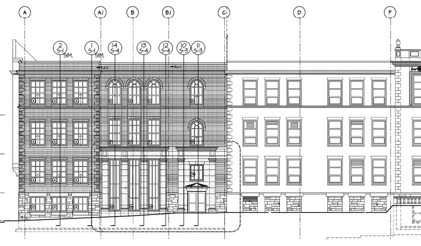
Let’s say you’re designing a building and part of your scope is the exterior wall framing, or “skin” of the building. You probably get sent some architectural plans that look something like this:
Figure 1. Sample building elevation with section marks.
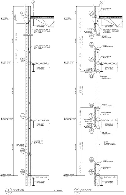
The architectural elevations will have wall section marks indicated for different framing situations. Two sample wall sections are shown in Figure 2.
Figure 2. Sample building wall sections.
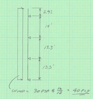
This building has several different wall section types that include door and window locations, varying parapet heights, diverse finish materials that need to meet different deflection criteria, and different connection points back to the base building. The traditional design calculation that you would need to run for one wall section might begin with a loading diagram similar to Figure 3 below.
Figure 3. Sample calculation of wall stud loading diagram.
Once you have your loading diagram generated, you would need to use reference load tables or a computer analysis program to solve for the axial and moment demands, the reactions at the pinned supports, and the member deflections.
After you determine the demand loads, you would then need to select a CFS member with sufficient properties, and you may need to iterate a few times to find a solution that meets the load and deflection parameters. After you’ve selected a member with the right width, gauge and steel strength, you’ll need to select an angle clip that can handle the demand loads, as well as fasteners to connect the clip to the CFS stud and to the base building. You would also need to also check the member design to ensure that it complies with bridging or bracing requirements per AISI. Then, after all that, you’d have to repeat the process again for all of the wall section types for your project.
Figure 4. Hmm, CFS design would sure be a lot easier if buildings were just huge windowless boxes…
Just writing out that whole process took some time, and you can imagine that actually running the calculations takes quite a bit longer. I think we can all agree that the design process we’ve outlined is time-consuming, and here’s where using CFS Designer™ to streamline your design process can really help.
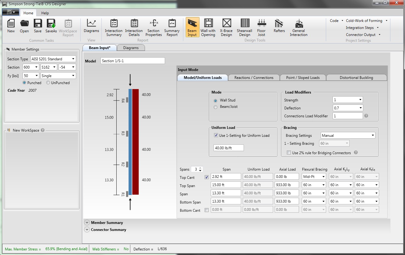
CFS Designer is a structural engineering design program that can automate many of the manual steps that are required in the design process. It has an easy-to-understand graphical user interface that allows you to input your project parameters within a variety of design modules from walls and beams, jambs and headers, X-brace walls, shearwalls, floor joists, and roof rafters. The program also enables the design of single stud or track members, built-up box-sections, back-to-back sections, and nested stud or track sections. Figure 5 shows an example of how you would input the same stud we looked at before into the program.
Figure 5. CFS Designer™ user interface for wall stud design.
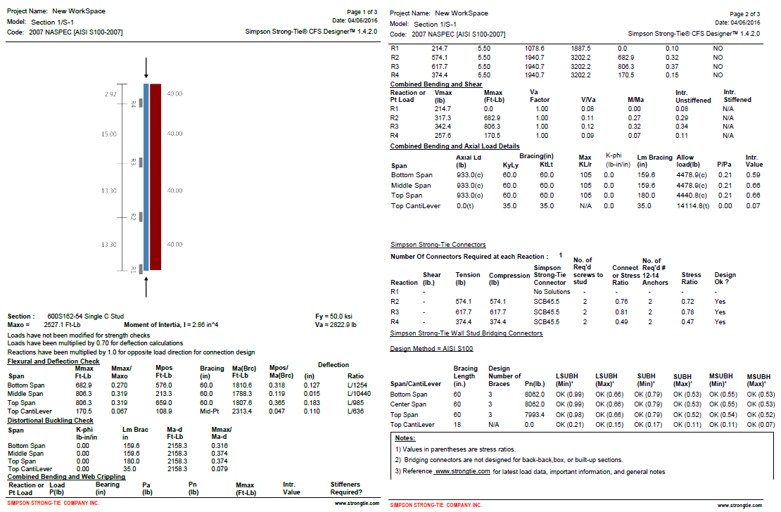
The program will generate the loading diagrams and complete calculation package for all of these different situations. And along with checking the member properties and deflection limits, CFS Designer will also check bridging and bracing requirements and provide connector solutions for the studs using tested and code-listed Simpson Strong-Tie products. Figure 6 shows an example of the summary output you would receive.
Figure 6. The comprehensive summary output page that covers the complete member design down to the bracing and connection solutions.
One unique part of the output is toward the center of the second page, under the heading “Simpson Strong-Tie Connectors.” This section summarizes the tension and compression loads at each reaction point and then shows a connector solution (such as the SCB45.5) along with the number of screws to the stud and the number of #12 sheet-metal screws to anchor back to the base building. Simpson Strong-Tie has developed and tested a full array of connectors specifically for CFS curtain-wall construction as well as for interior tenant improvement framing, which allows designers to select a connection clip straight out of a catalog without needing to calculate their own designs per the code. It’s just another way we’re helping you to get a little leaner!
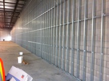
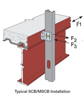
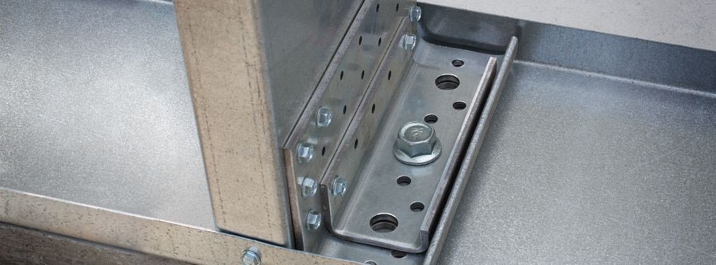
The last part of the output shown in Figure 6 is titled “Simpson Strong-Tie Wall Stud Bridging Connectors.” It checks the bridging and bracing requirements per AISI S100 and selects a SUBH bridging connector, an innovative bridging solution developed by Simpson Strong-Tie that snaps into place and achieves design loads while only requiring one #10 screw to connect for 75% of applications.
Figure 8. A close-up of the SUBH installed (left) and a wall of studs with bridging installed using the LSUBH clips (right).
You can download a free trial of CFS Designer™ and give it a test drive to see how much time it can save you on a design project. The trial version has almost full functionality, with the exception of not being able to print the output sheets. You can see purchasing information online, and you should always feel free to contact your local Simpson Strong-Tie engineering department with any questions you may have. I hope you are able to take advantage of this great tool to further improve your everyday design processes. We will be sure to keep you updated on our latest technology tools that help speed up the design process. If you’re using CFS Designer, we’d like to hear your thoughts about the program. Please share them in the comments below.
A previous blog post described how Simpson Strong-Tie tests and loadrates connectors used with cold-formed steel structural members per acceptance criteria ICC-ES AC261.
This week, I would like to describe how we test and determine engineering design values for RCKW, Rigid Connector Kneewall, in a CFS wall assembly and how the data can help designers perform engineering calculations accurately and efficiently.Continue Reading
We use cookies on this site to enhance your user experience. By clicking "I AGREE" below, you are giving your consent for us to set cookies. Privacy PolicyI AGREE
Privacy & Cookies Policy
Privacy Overview
This website uses cookies to improve your experience while you navigate through the website. Out of these cookies, the cookies that are categorized as necessary are stored on your browser as they are essential for the working of basic functionalities of the website. We also use third-party cookies that help us analyze and understand how you use this website. These cookies will be stored in your browser only with your consent. You also have the option to opt-out of these cookies. But opting out of some of these cookies may have an effect on your browsing experience.
Necessary cookies are absolutely essential for the website to function properly. This category only includes cookies that ensures basic functionalities and security features of the website. These cookies do not store any personal information.
Any cookies that may not be particularly necessary for the website to function and is used specifically to collect user personal data via analytics, ads, other embedded contents are termed as non-necessary cookies. It is mandatory to procure user consent prior to running these cookies on your website.